Antenna Theory and Design Associate Professor WANG Junjun


 typically")


 is")


 region is defined as “that region")


- Slides: 55
Antenna Theory and Design Associate Professor: WANG Junjun 王珺珺 School of Electronic and Information Engineering Beihang University wangjunjun@buaa. edu. cn 13426405497 New Main Building, F 1025
Chapter 2 Fundamental Antenna Parameters
Chapter 2 Fundamental antenna parameters • Many definitions are from the IEEE Standard Definitions of Terms for Antennas (IEEE Std 145 -1983). ▫ Radiation patterns ▫ Radiation power density ▫ Radiation intensity ▫ Beam efficiency ▫ Beam width ▫ Antenna efficiency ▫ Directivity and gain ▫ Polarization ▫ Bandwidth ▫ Input impedance ▫ Radiation efficiency
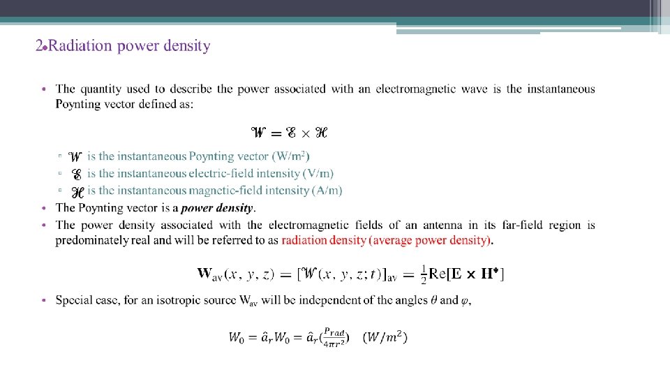
1. Radiation patterns • An antenna radiation pattern or antenna pattern is defined as “a mathematical function or a graphical representation of the radiation properties of the antenna as a function of space coordinates. In most cases, the radiation pattern is determined in the far field region and is represented as a function of the directional coordinates. Radiation properties include power flux density, radiation intensity, field strength, directivity, phase or polarization. ” • The radiation property of most concern is the two or three dimensional spatial distribution of radiated energy as a function of the observer’s position along a path or surface of constant radius.
1. Radiation patterns
1. Radiation patterns For most practical applications, a few plots of the pattern as a function of θ for some particular values of φ, plus a few plots as a function of φ for some particular values of θ, give most of the useful and needed information. 3 -D coordinate system for antenna analysis
1. Radiation patterns • For an antenna, the a. field pattern(in linear scale) typically represents a plot of the magnitude of the electric or magnetic field as a function of the angular space. b. power pattern(in linear scale) typically represents a plot of the square of the magnitude of the electric or magnetic field as a function of the angular space. • c. power pattern(in d. B) represents the magnitude of the electric or magnetic field, in decibels, as a function of the angular space. This scale is usually desirable because a logarithmic scale can accentuate in more details those parts of the pattern that have very low values, which later we will refer to as minor lobes. • Dividing a field/power component by its maximum value, we obtain a normalized or relative filed/power pattern which is a dimensionless number with maximum value of unity.
All three patterns yield the same angular separation between the two half-power points, on their respective patterns, referred to as HPBW a. field pattern at 0. 707 value of its maximum b. power pattern (in a linear scale) at its 0. 5 value of its maximum c. power pattern (in d. B) at − 3 d. B value of its maximum 2 -D normalized field pattern( linear scale), power pattern(linear scale), and power pattern ( in d. B) of a 10 -element linear array with a spacing of d = 0. 25λ The plus (+) and minus (−) signs in the lobes indicate the relative polarization of the amplitude between the various lobes, which changes (alternates) as the nulls are crossed. All three patterns yield the same angular separation between the two half-power points, 38. 64.
1. 1 Radiation pattern lobes • Various parts of a radiation pattern are referred to as lobes, which may be subclassified into major or main, minor, side, and back lobes. • A radiation lobe is a “portion of the radiation pattern bounded by regions of relatively weak radiation intensity. ” (a) Radiation lobes and beamwidths of an antenna 3 -D polar pattern. (b) Linear 2 -D plot of power pattern (one plane of (a)) and its associated lobes and beamwidths.
1. 1 Radiation pattern lobes • A major lobe (also called main beam) is defined as “the radiation lobe containing the direction of maximum radiation. ” • A minor lobe is any lobe except a major lobe. • A side lobe is “a radiation lobe in any direction other than the intended lobe. ” (Usually a side lobe is adjacent to the main lobe and occupies the hemisphere in the direction of the main beam. )
1. 1 Radiation pattern lobes • A back lobe is “a radiation lobe whose axis makes an angle of approximately 180◦ with respect to the beam of an antenna. ” Usually it refers to a minor lobe that occupies the hemisphere in a direction opposite to that of the major (main) lobe. • Minor lobes usually represent radiation in undesired directions, and they should be minimized. • Side lobes are normally the largest of the minor lobes. The level of minor lobes is usually expressed as a ratio of the power density in the lobe in question to that of the major lobe. This ratio is often termed the side lobe ratio or side lobe level.
1. 2 Isotropic, Directional, and Omnidirectional Patterns • An isotropic radiator is defined as “a hypothetical lossless antenna having equal radiation in all directions. ” • A directional antenna is one “having the property of radiating or receiving electromagnetic waves more effectively in some directions than in others. This term is usually applied to an antenna whose maximum directivity is significantly greater than that of a half-wave dipole. ” Principal E- and H-plane patterns for a pyramidal horn antenna Omnidirectional antenna pattern
1. 2 Isotropic, Directional, and Omnidirectional Patterns • An omnidirectional antenna is defined as one “having an essentially nondirectional pattern in a given plane (in this case in azimuth, f (φ), θ = π/2) and a directional pattern in any orthogonal plane (in this case in elevation, g(θ), φ = constant). ” An omnidirectional pattern is then a special type of a directional pattern. Principal E- and H-plane patterns for a pyramidal horn antenna Omnidirectional antenna pattern
1. 2 Isotropic, Directional, and Omnidirectional Patterns • The E-plane is defined as “the plane containing the electric field vector and the direction of maximum radiation, ” and the H-plane as “the plane containing the magnetic-field vector and the direction of maximum radiation. ” • Although it is very difficult to illustrate the principal patterns without considering a specific example, it is the usual practice to orient most antennas so that at least one of the principal plane patterns coincide with one of the geometrical principal planes. Principal E- and H-plane patterns for a pyramidal horn antenna Omnidirectional antenna pattern
1. 4 Field regions • The space surrounding an antenna is usually subdivided into three regions: (a) reactive nearfield, (b) radiating near-field (Fresnel) and (c) far-field (Fraunhofer) regions. • These regions are so designated to identify the field structure in each. • Although no abrupt changes in the field configurations are noted as the boundaries are crossed, here are distinct differences among them. The boundaries separating these regions are not unique, although various criteria have been established and are commonly used to identify the regions.
1. 4 Field regions 1. Reactive near-field region is defined as “that portion of the near-field region immediately surrounding the antenna wherein the reactive field predominates. ” For a very short dipole, or equivalent radiator, the outer boundary is commonly taken to exist at a distance λ/2π from the antenna surface. λ is the wavelength and D is the largest dimension of the antenna.
1. 4 Field regions 2. Radiating near-field (Fresnel) region is defined as “that region of the field of an antenna between the reactive near-field region and the far-field region wherein radiation fields predominate and wherein the angular field distribution is dependent upon the distance from the antenna. If the antenna has a maximum dimension that is not large compared to the wavelength, this region may not exist. For an antenna focused at infinity the radiating near-field region is sometimes referred to as the Fresnel region on the basis of analogy to optical terminology. If the antenna has a maximum overall dimension which is very small compared to the wavelength, this field region may not exist. ” This criterion is based on a maximum phase error of π/8. λ is the wavelength and D is the largest dimension of the antenna.
1. 4 Field regions λ is the wavelength and D is the largest dimension of the antenna.
1. 4 Field regions • It is apparent that in the reactive nearfield region the pattern is more spread out and nearly uniform, with slight variations. • As the observation is moved to the radiating near-field region(Fresnel), the pattern begins to smooth and form lobes. • In the far-field region (Fraunhofer), the pattern is well formed, usually consisting of few minor lobes and one, or more, major lobes.
1. 4 Field regions It is observed that the patterns are almost identical, except for some differences in the pattern structure around the first null and at a level below 25 d. B. Because infinite distances are not realizable in practice, the most commonly used criterion for minimum distance of farfield observations is 2 D 2/λ. Calculated radiation patterns of a paraboloid antenna for different distances from the antenna.
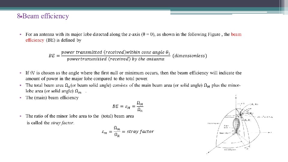
4 Beamwidth • The beamwidth of a pattern is defined as the angular separation between two identical points on opposite side of the pattern maximum. • In an antenna pattern, there a number of beamwidths. • One of the most widely used beamwidths is the Half-Power Beamwidth (HPBW), which is defined by IEEE as: “In a plane containing the direction of the maximum of a beam, the angle between the two directions in which the radiation intensity is one-half value of the beam. ” • The angular separation between the first nulls of the pattern is referred to as the First-Null Beamwidth (FNBW).
4 Beamwidth • However, in practice, the term beamwidth, with no other identification, usually refers to HPBW. • The beamwidth of an antenna is a very important figure of merit and often is used as a trade-off between it and the side lobe level; that is, as the beamwidth decreases, the side lobe increases and vice versa. • In addition, the beamwidth of the antenna is also used to describe the resolution capabilities of the antenna to distinguish between two adjacent radiating sources or radar targets.
4 Beamwidth • The most common resolution criterion states that the resolution capability of an antenna to distinguish between two sources is equal to half the first-null beamwidth (FNBW/2), which is usually used to approximate the half power beamwidth (HPBW). • That is, two sources separated by angular distances equal or greater than FNBW/2 ≈ HPBW of an antenna with a uniform distribution can be resolved. If the separation is smaller, then the antenna will tend to smooth the angular separation distance.
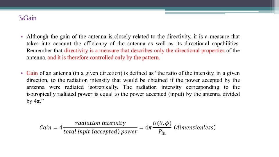
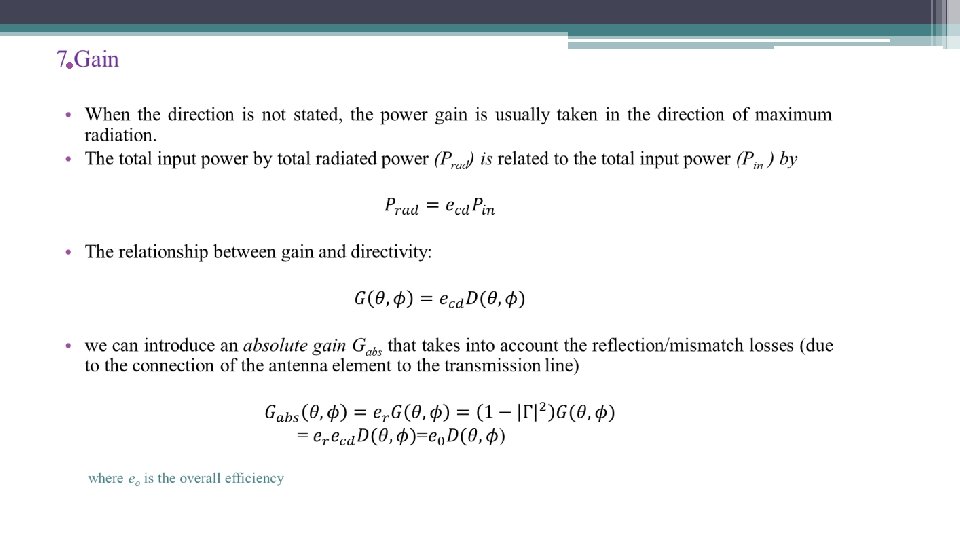
5 Directivity • The directivity of an isotropic source is unity since its power is radiated equally well in all directions. For all other sources, the maximum directivity will always be greater than unity, and it is a relative “figure of merit” which gives an indication of the directional properties of the antenna as compared with those of an isotropic source. • The directivity can be smaller than unity, in fact it can be equal to zero. The values of directivity will be equal to or greater than zero and equal to or less than the maximum directivity (0 ≤ D 0).
6 Antenna efficiency • Associated with an antenna are a number of efficiencies. • The total antenna efficiency e 0 is used to take into account losses at the input terminals and within the structure of the antenna. Losses due to: 1. reflections because of the mismatch between the transmission line and the antenna 2. I 2 R losses (conduction and dielectric) Usually ec and ed are very difficult to compute, but they can be determined experimentally. Even by measurements they cannot be separated, and it is usually more convenient to write as where ecd = eced = antenna radiation efficiency, which is used to relate the gain and directivity.
9 Bandwidth • The bandwidth of an antenna is defined as “the range of frequencies within which the performance of the antenna, with respect to some characteristic, conforms to a specified standard. ” • The bandwidth can be considered to be the range of frequencies, on either side of a center frequency (usually the resonance frequency for a dipole), where the antenna characteristics are within an acceptable value of those at the center frequency.
9 Bandwidth • For broadband antennas, the bandwidth is usually expressed as the ratio of the upper-tolower frequencies of acceptable operation. For example, a 10: 1 bandwidth indicates that the upper frequency is 10 times greater than the lower. For narrowband antennas, the bandwidth is expressed as a percentage of the frequency difference over the center frequency of the bandwidth.
10 Polarization • Polarization of an antenna in a given direction is defined as “the polarization of the wave transmitted (radiated) by the antenna. Note: When the direction is not stated, the polarization is taken to be the polarization in the direction of maximum gain. ” • In practice, polarization of the radiated energy varies with the direction from the center of the antenna, so that different parts of the pattern may have different polarizations.
10 Polarization • Polarization of a radiated wave is defined as “that property of an electromagnetic wave describing the time-varying direction and relative magnitude of the electric-field vector; specifically, the figure traced as a function of time by the extremity of the vector at a fixed location in space, and the sense in which it is traced, as observed along the direction of propagation. ” • Polarization then is the curve traced by the end point of the arrow (vector) representing the instantaneous electric field. The field must be observed along the direction of propagation.
37 10 Polarization Property of R Struzak Polarization states LHC UPPER HEMISPHERE: ELLIPTIC POLARIZATION LEFT_HANDED SENSE LATTITUDE: REPRESENTS AXIAL RATIO EQUATOR: LINEAR POLARIZATION LOWER HEMISPHERE: ELLIPTIC POLARIZATION RIGHT_HANDED SENSE POLES REPRESENT CIRCULAR POLARIZATIONS (Poincaré sphere) 450 LINEAR RHC LONGITUDE: REPRESENTS TILT ANGLE
10 Polarization Rotation of a plane electromagnetic wave and its polarization ellipse at z = 0 as a function of time.
10 Polarization • The polarization of a wave can be defined in terms of a wave radiated (transmitted) or received by an antenna in a given direction. • The polarization of a wave received by an antenna is defined as the “polarization of a plane wave, incident from a given direction and having a given power flux density, which results in maximum available power at the antenna terminals. ”
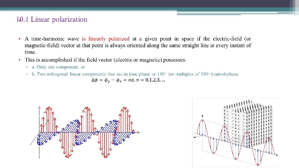
10. 1 Linear polarization • The instantaneous field of a plane wave, traveling in the negative z direction, can be written as • The instantaneous components are related to their complex counterparts by where Exo and Eyo are, respectively, the maximum magnitudes of the x and y components.
10. 2 Circular polarization • A time-harmonic wave is circularly polarized at a given point in space if the electric (or magnetic) field vector at that point traces a circle as a function of time. • The necessary and sufficient conditions to accomplish this are if the field vector (electric or magnetic) possesses all of the following: ▫ a. The field must have two orthogonal linear components, and ▫ b. The two components must have the same magnitude, and ▫ c. The two components must have a time-phase difference of odd multiples of 90◦.
43 10. 2 Circular polarization Right Hand Circular Polarization RHCP coaxial feed point LHCP coaxial feed point y Left Hand Circular Polarization x
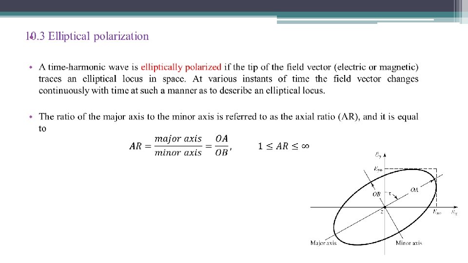
10. 3 Elliptical polarization • The necessary and sufficient conditions to accomplish this are if the field vector (electric or magnetic) possesses all of the following: ▫ a. The field must have two orthogonal linear components, and ▫ b. The two components can be of the same or different magnitude. ▫ c. (1) If the two components are not of the same magnitude, the time-phase difference between the two components must not be 0◦ or multiples of 180◦ (because it will then be linear). ▫ (2) If the two components are of the same magnitude, the time-phase difference between the two components must not be odd multiples of 90◦ (because it will then be circular).
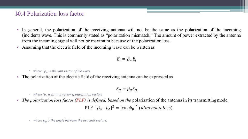
10. 4 Polarization loss factor • If the antenna is polarization matched, its PLF will be unity and the antenna will extract maximum power from the incoming wave. PLF for transmitting and receiving aperture antennas
10. 4 Polarization loss factor The polarization loss must always be taken into account in the link calculations design of a communication system because in some cases it may be a very critical factor. PLF for transmitting and receiving linear wire antennas
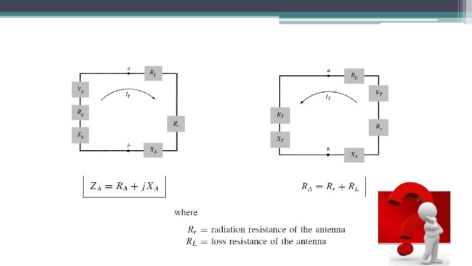
11 Input impedance • Input impedance is defined as “the impedance presented by an antenna at its terminals or the ratio of the voltage to current at a pair of terminals or the ratio of the appropriate components of the electric to magnetic fields at a point. ” • The input impedance of an antenna is generally a function of frequency. Thus the antenna will be matched to the interconnecting transmission line and other associated equipment only within a bandwidth. • In addition, the input impedance of the antenna depends on many factors including its geometry, its method of excitation, and its proximity to surrounding objects. Because of their complex geometries, only a limited number of practical antennas have been investigated analytically. For many others, the input impedance has been determined experimentally.
11 Input impedance Thevenin equivalent circuit of an antenna in transmitting mode? • .
• Conclusions 1. The definition of antenna parameters. 2. How to describe the radiation pattern, input impedance bandwidth, gain and efficiency of an antenna. • .
• Questions: • Thevenin equivalent circuit of an antenna in receiving mode? • .
• Maximum power-carrying capability occurs at a diameter ratio of 1. 65 corresponding to 30 -ohms impedance • Optimum diameter ratio for voltage breakdown is 2. 7 corresponding to 60 -ohms impedance (the standard impedance in many Europe countires) • Minimum attenuation impedance of 77 ohms (diameter ratio 3. 6). • The dielectric constant of polyethyle is 2. 3, impedance of a 77 ohm air line is reduced to 51 ohm when filled with polyethyle. • orthogonal polarization • Almost any coax that *looks* good for mechanical reasons just happens to come out at close to 50 ohms anyway. If you take a reasonable sized center conductor and put a insulator around that and then put a shield around that and choose all the dimensions so that they are convenient and mechanically look good, then the impedance will come out at about 50 ohms.
Thank you!