Small Magnetic Loop Antenna Design Project Design Goals


 6. For remote tuning, a low cost 12 volt hobby")
: A completely encircled antenna structure whose total")


,")
 LA CA")


: 7 MHz 10 MHz 14 MHz 18")
: 7 MHz 10 MHz 14 MHz 18 MHz 21 MHz 2.")


- Slides: 31
Small Magnetic Loop Antenna Design Project Design Goals: 1. To design and construct a small size, multiband transmitting loop antenna useful for QRP and portable operation. 2. To compare the performance of the loop antenna to a known antenna type to verify performance 3. Design will cover the 40 through 15 Meter Bands inclusively 4. To develop a computer spreadsheet to facilitate the design procedure
First Generation 30 inch Loop
First Generation Design 30 inch loop using Gamma Match
First Generation Shortcomings � Original design used a 30 inch loop which did not tune below 14 MHz, and had efficiency issues because of the 30 inch diameter and conductor diameter (0. 65 inches) � The gamma match produced a current imbalance in the loop (“antenna effect”), which distorted the radiation pattern
Specific Design Goals 1. 2. 3. 4. 5. Remote tuning At least 30 w power handling capability Portable for Field use Cost of materials not to exceed $100. 00 VSWR less than 1. 5 to 1 on all covered bands at resonance
Selection of materials 1 inch copper tubing was investigated at first, but was dismissed because of cost and weight. Design analysis indicated that a 42 inch diameter loop would provide a good compromise between array efficiency and frequency coverage. (ARRL Antenna Book, Antennas, by John Kraus)) A plastic gymnasium hoop had approximately the right diameter, is low cost and light in weight Could copper tape be used as the radiating conductor? Skin depth will have to be considered as one of the design tasks.
Selection of materials (continued) 6. For remote tuning, a low cost 12 volt hobby motor was selected at 0. 7 RPM. Motor rotates in both directions 7. The loop will use a single coax lead-in to the antenna, therefore a suitable power insertion system will be designed to feed the DC control voltage up the center conductor, along with the RF signal. A control box with reversing polarity control voltage will be part of the design. 8. Determine the type and range of the tuning capacitor to resonate the loop
Definitions: 1. Small loop: 2. Directivity (Gain): A completely encircled antenna structure whose total perimeter is below self-resonance The ratio of loop Field Strength (in the favored direction) compared to the Field Strength of an Isotropic Radiator (or dipole) 3. Loop Efficiency (Decimal or Percent): 4. Skin Depth (Skin Effect): The ratio of Loop Radiation Resistance divided by the Sum of Radiation Resistance plus Total Loss Resistance (Decimal). For percent, multiply decimal value by 100. The distance from the top of a conducting medium where the current density decreases to 1/є of its surface value (37%) Skin Depth is denoted as δ; 86% of the total current density is contained within 2δ.
Calculation of Skin Depth: Skin Depth Equation for pure copper conductor: δ ≈ 0. 002574 √F Where: δ is the skin depth in inches, and F is the Frequency in MHz At 7 MHz, δ ≈ 0. 973 x 10 -3 inches 2 x δ = 1. 95 x 10 -3 inches and, At 21 MHz, δ ≈ 0. 515 x 10 -3 inches 2 x δ = 1. 03 x 10 -3 inches
Worst case is 7 MHz, requiring the greatest RF current penetration. Since 1 mil = 10 -3 inches, at 7 MHz, a minimum conductor thickness of 1. 95 mils is required for at least 2δ depth of current density penetration. 3 M Copper Adhesive Tape has a conductor thickness of 2 mils, which satisfies the requirement, and was chosen for the radiating conductor.
Loop Design Procedure for Circular Loop: 1. Choose loop diameter, D, and radiator diameter, d, both in inches. D must be less than ≈ 3300 where f Пf is the highest frequency of the loop in MHZ. At 21 MHz, D must be less than 50 inches. 42 inches was chosen for this design, with radiator diameter of 1. 5 inches 2. Calculate the Loop Inductance, L: L (μ H) = 0. 005 D x { [ 7. 353 x ( LOG ( 8 x D / d )] – 6. 386 }
3. Calculate the Loop Inductive Reactance, XL, at the highest and lowest antenna frequencies : XL = 2 x П x F x L where: XL is Inductive Reactance in ohms F is the Frequency in MHZ (highest / lowest), and L is the Loop Inductance in μH calculated in Step 2 4. Calculate the distributed loop Self Capacitance, CS: CS (pf) ≈ 0. 2103 x D, with D again in inches 5. Calculate the required Capacitances to Resonate the Loop, C min and C max: C min = 106 / ( 2 x П x Fmax x XLH ) - CS, and C max = 106 / ( 2 x П x Fmin x XLL ) - CS, where: C min and C max are in pico-farads, Fmin / Fmax in MHZ XLH is the inductive reactance at the highest frequency XLL is the inductive reactance at the lowest frequency
6. Estimate Tuning capacitor Qc, or use published / measured capacitor Qc data. For estimate, use 2000 to 800 for standard variable capacitor, (fully meshed to unmeshed); and 3500 to 1000 for split rotor Butterfly type, (fully meshed to unmeshed). Refer to spreadsheet Steps 7 through 17 should be performed at the highest and lowest antenna frequencies. For these steps, XL is the inductive reactance at the associated frequency. 7. Calculate capacitor equivalent loss resistance, RC, from QC: RC = X L / Q C 8. Calculate Loop Radiator Loss Resistance, RL: RL = ( П x D x 0. 000083 x √ F ) / d, where D, d, and F are as previously defined 9. Total Loss Resistance, RT, is sum of RC + RL RT = R C + R L 10. Calculate Loop Radiation Resistance, RR: RR = 9. 926 x 10 -13 x F 4 x D 4 again, where, F is in MHZ, and D as previously defined
11. Calculate antenna efficiency, ζ, in percent: * ζ = {RR / (RT + RR )} x 100, ζ D = ζ / 100, which is efficiency expressed as a decimal 12. Calculate the total Loop Antenna Q: * Q = XL / (2 x( (RR + RT)) where: XL is the Loop Inductive Reactance, and RT is the total Loop Loss Resistance, RR is radiation resistance all as previously calculated 13. Calculate the Peak Voltage across the tuning Capacitor, VC: * VC = √ (P x XL x Q) where: P is the Peak Envelope Power driving the Loop, XL calculated from Step 3 * 14. Calculate the minimum plate spacing (inches) for the capacitor, SMin: SMin = 1. 5 x VC / 50000 (Includes 1. 5 to 1 safety factor at 50000 volts / in) * Choose a capacitor offering Cmin and Cmax values (Step 4), with this minimum plate spacing 15. Calculate the RMS Resonant Circulating Current in the Loop, IL: * IL ≈ 0. 7071 * VC / XL, provided that XL >> RT, which is the usual case 16: Calculate Loop Bandwidth, BW: * BW = F / Q, where F and BW are both in MHZ. * Steps 11 through 16 are within ≈ +/- 20% if Antenna VSWR is better than 1. 5 at resonance.
17. Antenna Gain Estimate: G d. B ≈ 10 x LOG ( ζ D ) + 1. 81 where: G d. B is the estimated free-space gain in d. B, referenced to an isotropic radiator, and ζ D is the decimal value of the antenna efficiency calculated in STEP 11.
Computer Aided Design by Spreadsheet: Spreadsheet permits Fast Design on Personal Computer by automating the design steps. Calculates all loop parameters except the design of the matching / coupling network, which is determined experimentally. Spreadsheet values are not displayed if loop size exceeds small loop criteria
Matching Network Design: From the Spreadsheet, the following values of Rp (Equivalent parallel resistance), are noted for a 42 inch diameter loop: 7 MHz 18 MHz 21 MHz RP = 62. 88 K ohms RP = 50. 34 K ohms RP = 39. 73 K ohms These values are calculated from network theory using the series to parallel transform theorem. Rp = Rs + Xs 2 / Rs Xp = Rp Rs / Xs where: Rs = Rc + Ra + Rr Xs = Loop Inductive Reactance , XL, calculated in Step 3 Can a single matching circuit be used on all bands?
Loop Series to Parallel Transformation (Antenna side of Network, using Transformer Coupling) LA CA
Design a matching circuit to be close to a perfect match at ≈ 18 MHz, calculate the expected VSWR on the band edges. VSWR on 7 MHz: VSWR 7 MHz = RP 7 MHz / RP 18 MHz = 62. 88 / 50. 34 = 1. 25 VSWR on 21 MHz: VSWR 21 MHz = RP 18 MHz / Rp 21 MHz = 50. 34 / 39. 73 = 1. 27 From above data, a single coupling loop match of proper spacing would meet the design goal of VSWR less than 1. 5 on all bands
Realization of Transformer Match Secondary coupling loop approx 1/5 diameter of main loop, distance determined experimentally
Transformer match detail
Loop after construction and Initial Tests:
Photo of Tuning Unit:
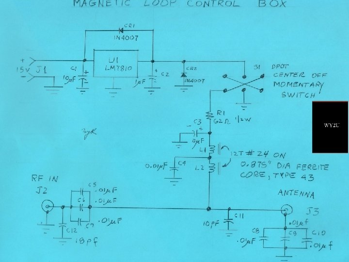
Tuning Unit Schematic Diagram
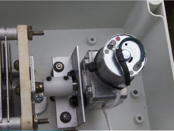
Control Box Photograph:
Measured Performance: VSWR (measured using MFJ-469 Analyzer): 7 MHz 10 MHz 14 MHz 18 MHz 21 MHz 1. 2 1. 3 1. 1 1. 3 7 – 21 MHz Met the design goal of VSWR < 1. 5 Tuning Time: Approximately 35 seconds 7 MHz to 21 MHz Qualitative Gain (switching back-and-forth compared to ground mounted vertical (one hop propagation ) 7 MHz vertical better by approximately 1 S Unit 10 MHz vertical better by approximately ½ S Unit 14 MHz no discernible difference 18 MHz approximately ½ S Unit better on loop 21 MHz approximately ½ S Unit better on loop Antenna was mounted in vertical orientation Power Capability: Tuning Capacitor warm to the touch at 30 watts when keyed for 30 seconds on 7, 10, and 14 MHz bands. Antenna slightly warm on 7 MHz band. No evidence of arcing on any band at 30 watts. Very little capacitor temperature rise noted on 18 and 21 MHz bands. Antenna, itself did not show any rise in temperature on bands above 7 MHz.
Measured Performance (Continued): 7 MHz 10 MHz 14 MHz 18 MHz 21 MHz 2. 6 to 1 VSWR Bandwidth: Measured Spreadsheet approximately 12 KHz 11. 2 KHz approximately 20 KHz 19. 9 KHz approximately 46 KHz 43. 2 KHz approximately 96 KHz 92. 5 KHz approximately 170 KHz 159. 6 KHz Measurements are in close agreement with the Spreadsheet.
Priced Bill of Materials: Item Control Box Plastic enclosure Antenna Tuning enclosure Hobby motor 0. 7 rpm Variable Capacitor (20 -360 pf) SO-239 connectors. 875 in OD Type 43 Ferrite Tantalum Capacitors Disc Capacitors 10 volt regulator (LM-7810) 1 N 4007 Diode 42 in Snap Together Hoop (Amazon) Dip mica capacitors Vector Board DPDT Momentary Switch 2 pin Power connector with mate Miscellaneous wire and hardware Copper Tape (average 1 roll) Total Qty 1 1 3 3 2 10 1 2 1 3 1 1 3 A/R Unit Price 3. 50 6. 50 5. 50 20. 50 3. 00 2. 00. 25 1. 50. 25 9. 00. 50 2. 00 (est) 12. 00 (est) Ext 3. 50 6. 50 5. 50 20. 50 9. 00 6. 00 4. 00 2. 50 1. 50 9. 00 1. 50 2. 00 12. 00 $89. 50
Summary: 1. Design goal was achieved, to construct a low cost, small size loop antenna. 2. VSWR was less than 1. 5 on all bands using a single Coupling Loop Match section 3. Qualitative Gain performance was within 1 S Unit of ground mounted vertical mono-pole on 7 and 10 MHz, equal or better on higher bands. 4. Power handling up to 30 watts PEP. 5. Priced Bill of materials less than the design goal budget of $100. 00 6. Could be an attractive antenna for portable use, or by an amateur who does not have the space for a full sized outdoor antenna 7. Spreadsheet is available via email (Excel) Any Questions? Thank you and See you all on the air Mike Kozma 73 de WY 2 U dmkozma@optonline. net