AnNajah National University Faculty Of Engineering Electrical Engineering


 Permanent split capacitor (PSC) 5) Shaded. Pole")


 voltage level.")


 has been")


")


")

 filter used to see the wave *PWM 2 signal is the")
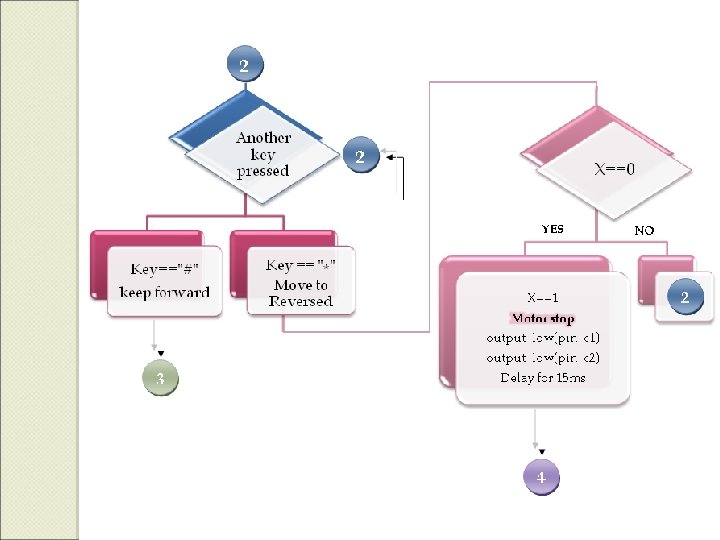
 pressed YES 3 NO 2")

 Splitting")

 Microprocessor 1 40 PIC Basic")


- Slides: 47
An-Najah National University Faculty Of Engineering Electrical Engineering Department PREPARED BY: SUPERVISOR:
Theoretical Part
1ϕ AC Power supply Lifetime & Maintenance smallhorsepower applications
3) Permanent split capacitor (PSC) 5) Shaded. Pole
THE MOTOR WE USED A run-type capacitor permanently connected in series with the start (Aux. ) winding. It provides the 90 degree phase shift between main & aux. This 90 degree will be done by programming.
Measured motor Specifications NO LOAD PARAMETERS: In. L=0. 38 A, W= 1436 rpm LOADED MOTOR PARAMETERS: Pout=86 w η=85%= pout/pin If. L = 0. 45 A Turns Ratio (α)=3. 33 TORQUE MEASUREMENT: T=L*F= 0. 6*130=78 N. m
Applications On SPI Motors Gate operators Fans, Blowers SPIM App. Where instant reversing Is needed Garage Door Openers
Speed Direction
Gear mechan -isms External relays Unfortunately, all of these components increase the cost of the system for basic ON and OFF control in two directions. Historically Bidirectiona l. Switches
It is to be connected to the neutral point of the AC power supply, ** 2 Channels PWM, ** (-E/2 to E/2) voltage level
** 3 Channels PWM. ** (0 to E) voltage level.
ØThe direction of rotation can be easily controlled by shifting Vc 180° from both Va & Vb.
-Air gap flux level becomes greater than normal -The saturation in flux resultting can cause an excessive magnetizing current. V/Hz Decreazing the developed tourqe Constant V/F resulting the motors to produce their rated torque over the widest possible speed range.
Practical Part
DESIGN DESCRIPTION Software Hardware DESIGN
�OVERALL BLOCK DIAGRAM
�ALGORITHMIC BLOCK DIAGRAM
FULL CIRCUIT PREVIEW
IGBT 3 -Phase Inverter Bridge Rectifier 3 -Phase Bridge Driver Optocoupler Hardware Design Dead Band time Generator DC Chopper Keypad & LCD Connection PIC Microcontroller Basic cct
PIC MICROCONTROLLER BASIC CCT KEYPAD + LCD CONNECTION
Single Phase Full-Wave Bridge Rectifier The full bridge rectifier (KBPC 35 -10) has been used to convert the ac supply to a dc voltage Vdc
ØA dc chopper is a dc-to-dc voltage converter ØThe MOSFET allows current from the source to pass through it, but when it allows current to pass through it is governed by the pulse wave modulator (PWM). The PWM creates pulses, and the high section of these pulses turns on the MOSFET. ØThe longer the MOSFET is turned on, the faster the motor spins.
� This cct is used In order to avoid cross conduction of the two IGBT switches in the same arm. � The simple circuit shown can be used to introduce any desired amount of deadband time between Vo 1 and Vo 2 control pulses. Dead Band Time CCT
GATE DRIVER Driving a MOSFET or IGBT in the high side position of a half-bridge topology or 3 phase inverter leg offers the additional challenge that the gate voltage is referenced to the source rather than to ground. Noise immunity ensures that the MOSFET or IGBT doesn't turn on accidentally
v. AC inverters are used to convert DC voltage to AC voltage to feed the motor under control. v. It is used to vary the frequency. v. Also it will be the main element in direction control of the motor.
q Switches can be: MOSFET Transistors, GTOs IGBTs …. We choose IGBT for: 1) Like MOSFET in gating: Lower gate voltages for turn-on & turn-off. 2) Transistor in conduction: it can be pulled to nonconduction state in shorter time 3) Needs approximately 1μsec to turn on or off
** Source and destination are at very different voltage levels. OPTOCOUPLER ** So without making an electrical connection we can protect the Microprocessor from overvoltage damage using this OPTOCOUPLER
Forward Reverse Three-Phase Inverter Bridge
The winding voltages, Va, Vb, and Vc, should be controlled to achieve the phase difference between the effective voltages across the main and starting windings, in order to have a 90 -degree phase shift to each other.
The direction of rotation can be easily controlled by shifting Vc 180°.
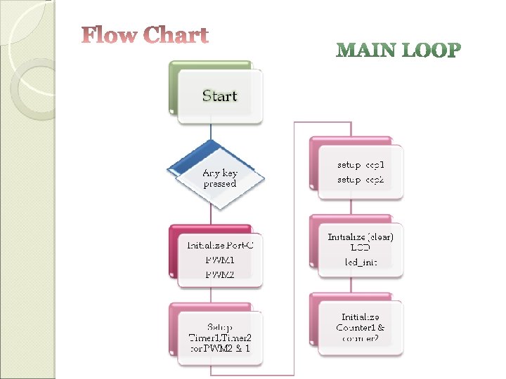
PWM Direction control Generation Software Design Speed Control Flow chart PIC Microcontroller
Port-B: For keypad Port-D: For LCD Port-C: RC 1 for CCP 2 (PWM 1) RC 2 for CCP 1 (PWM 2)
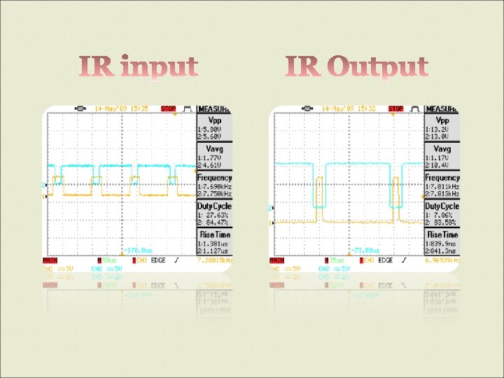
To achieve 90º between main & aux: * Semi sinusoidal waveforms. * Nearly high frequency (around 7 KHz was used).
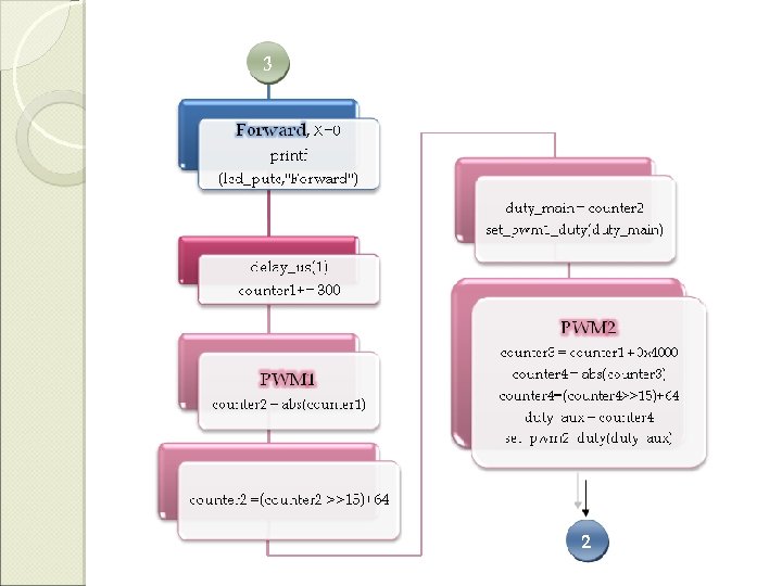
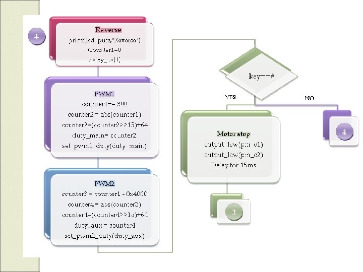
*R-C (low pass) filter used to see the wave *PWM 2 signal is the same but with 90º phase shift (± 0 x 4000, according to the direction of rotation).
key (#) pressed YES 3 NO 2
Problems & Constraints PROBLEM #1 DC-CHOPPER: VGS threshold voltage of the MOSFET used Solution: Optocoupler PROBLEM #2 DEAD BAND TIME: Can’t trigger two IGBTs in the same arm at the same time Solution: Hardware circuit
PROBLEM #3 IGBT GATE DRIVER: Solution: 3 -phase bridge driver IC (IR 21363) Splitting grounds of low&high sides Auxiliary power supply Not enough to trigger the gate. Switching Frequency
PROBLEM #4 INVERTER GATES SWITCHING: Topologies applied to trigger IGBT gates Solution: Signals that approximately introduces the sinusoidal one
THE COST ELEMENTS # OF NEEDED ELEMENTS COST (NIS) Microprocessor 1 40 PIC Basic cct 1 30 Single phase ACmotor 1 120 LCD 1 40 keypad 1 35 MOSFET 1 10 IGBT 6 120 un. Controlled rectifier 1 30 Optocouplers 1 7 -- 100 IR 21363 1 80 Shmitt & invertres 5 20 Resistors & Overall Cost= 632 NIS Capacitors
WE LEARNT A LOT ABOUT EVERY THING, Especially: “HOW TO BE PATIENT” ot l a s fer f i d k r o ne o w l l a a tic e c r a o r P he t m fro Ever corr y part n ect f requ eeds to have ency requ to ope the rate ired. as This w ork h appli ere ca ed to n be a 3 -pha lso se AC moto rs "DON'T LET THIS CONTROLPROJECT SIT IN A BIG FOLDER AND NOT BE ACTED UPON!!
RECOMMENDATIONS First of all we DON’T recommend anyone, anywhere, for any purpose to experiment with the work of this project again. e b t ’ Don nted, oi p ! p D a R dis HA S r I e E m LIF Dr. Sa K & AS out that ab Make sure that high and low side grounds are separated • Always DOUBLE CHECK on your work before turning on any supply, because an important & expensive part in your circuit might be ON FIRE!