2 2 ion selectivity control sodium channel potassium
 단백질에 의한")
 An electronic stimulator supplies")

 - EEG (electroencephalograph) -")

 Ý ã 입력 증가분에 대한 출력 증가분 선형성 (Linearity) x 1")
 = (c) (a), (c) > (b) Sensitivity (a) > (c) Yonsei Med.")


 Macroshock, externally applied current spreads throughout")
")

 : power & signal ã 접지 (ground) ã")
- Slides: 38
2. 세포막의 구조 ã ã ã ã 지방의 2중층 이온전달 (ion selectivity) 단백질에 의한 물질이동 control sodium channel potassium channel 외부자극에 의해 cell 흥분 막전위 Vm = Φi - Φo 세포도 일종의 membrane의 벽을 갖는 capacitance 역할 Yonsei Med. Instr. Lab
Recording of action potential of an invertebrate nerve axon (a) An electronic stimulator supplies a brief pulse of current to the axon, strong enough to excite the axon. A recording of this activity is made at a downstream site via a penetrating micropipet. (b) The movement artifact is recorded as the tip of the micropipet drives through the membrane to record resting potential. A short time later, an electrical stimulus is delivered to the axon; its field effect is recorded instantaneously at downstream measurement site as the stimulus artifact. The action potential proceeds along the axon at a constant propagation velocity. The time period L is the latent period or transmission time from stimulus to recording site. Yonsei Med. Instr. Lab
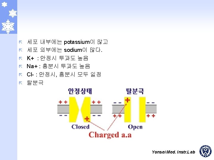
4. 활동전압의 생성 안정상태 : K+ channel open, K+ 유출, PNa << PK ã 흥분상태 : Na+ channel open, Na+ 유입, PK << PNa ã Yonsei Med. Instr. Lab
6. 생체 전기현상의 기록 ã 생체전기현상 기록기 - ECG (electrocardiograph) - EEG (electroencephalograph) - ENG (electro neurography) - EMG (electromyograph) - ERG (electroretinograph) - EGG (electro gastrography) - EOG (electrooculogram) Yonsei Med. Instr. Lab
No accuracy, and no precision No accuracy, but precision Accuracy, but no precision Accuracy, and precision Yonsei Med. Instr. Lab
ã 민감도 (Sensitivity) Ý ã 입력 증가분에 대한 출력 증가분 선형성 (Linearity) x 1 Linear system y 1 (x 1 + y 2) and x 2 ã ã (y 1 + y 2) and y 2 Kx 1 Linear system Ky 1 입력 범위 (Input Range) Ý ã Linear system 입력 허용 범위 입력 임피던스 (Input Impedance) 동적범위 (Dynamic Range) Ý Ý Range of the smallest and the largest 측정 가능 범위 Yonsei Med. Instr. Lab
Linearity (a) = (c) (a), (c) > (b) Sensitivity (a) > (c) Yonsei Med. Instr. Lab
생체계측 방법 Power source Sensor Measurand Primary Sensing element Calibration signal Control And feedback Variable Conversion element Signal processing Output display Data storage Data transmission Perceptible output Radiation, electric current, or other applied energy Generalized instrumentation system The sensor converts energy or information from the measurand to another form (usually electric). This signal is the processed and displayed so that humans can perceive the information. Elements and connections shown by dashed lines are optional for some applications. Yonsei Med. Instr. Lab
CRT Monitor or Chart recorder Sensor or Electrode Pre-Amplifier Monitor or Printer Filtering Main-Amplifier PC or Microprocessor Signal Conditioning • Gain • Offset Analog to Digital Converter Signal Processing Yonsei Med. Instr. Lab
Electrodes vecg Z 2 Zbody Z 1 +Vcc 60 -Hz ac magnetic field + Differential amplifier - Displacement currents vo -Vcc Simplified electrocardiographic recording system Two possible interfering inputs are stray magnetic fields and capacitively coupled noise. Orientation of patient cables and changes in electrode-skin impedance are two possible modifying inputs. Z 1 and Z 2 represent the electrode-skin interface impedances. Yonsei Med. Instr. Lab
Right leg electrode Sensing electrodes Lead-fail detect Amplifier protection circuit Lead selector Driven right leg circuit Isolation circuit Preamplifier Auto calibration ADC Driver amplifier Memory Recorder Ð printer Isolated power supply Baseline restoration Parallel circuits for simultaneous recordings from different leads Microcomputer Operator display Control program Keyboard ECG analysis program Block diagram of an electrocardiograph Yonsei Med. Instr. Lab
Design process for medical instruments Choice and design of instruments are affected by signal factors, and also by environmental, medical, and economic factors. (Revised from Transducers for Biomedical Measurements: Application and Design, by R. S. C. Cobbold. Copyright 1974, John Wiley and Sons, Inc. Used by permission of John Wiley and Sons, Inc. ) Yonsei Med. Instr. Lab
Voltage and frequency ranges of some common biopotential signals; dc potentials include intracellular voltages as well as voltages measured from several points on the body. EOG is the electrooculogram, EEG is the elctroencephalogram, ECG is the electrocardiogram, EMG is the electromyogram, and AAP is the axon action potential. (From J. M. R. Delgado, “Electrodes from Extracellular Recording and Stimulation, ” in Physical Techniques in Biological Research, edited by W. L. Nastuk, New York: Academic Press, 1964. ) Yonsei Med. Instr. Lab
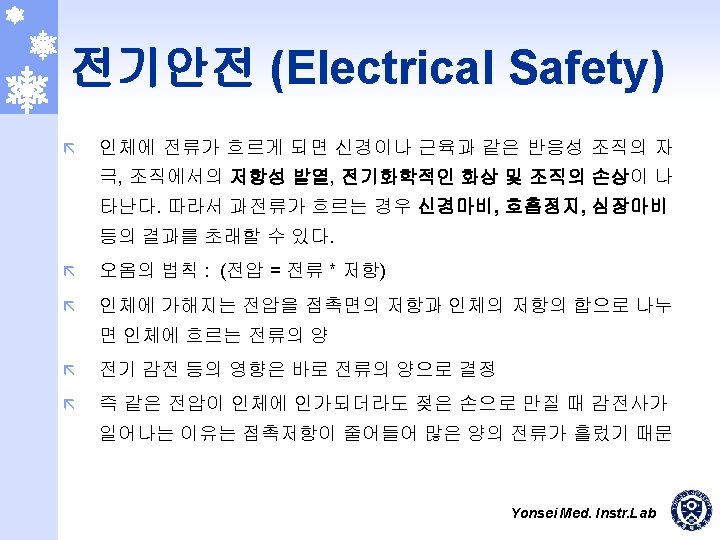
Physiological effects of electricity Threshold or estimated mean values are given for each effect in a 70 kg human for a 1 to 3 s exposure to 60 Hz current applied via copper wires grasped by the hands. Yonsei Med. Instr. Lab
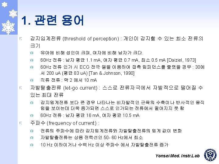
Distrubutions of perception thresholds and let-go currents These data depend on surface area of contact (moistened hand grasping AWG No. 8 copper wire). (Replotted from C. F. Dalziel, "Electric Shock, " Advances in Biomedical Engineering, edited by J. H. U. Brown and J. F. Dickson IIII, 1973, 3, 223 -248. ) Yonsei Med. Instr. Lab
Let-go current versus frequency Percentile values indicate variability of let-go current among individuals. Let-go currents for women are about two-thirds the values for men. (Reproduced, with permission, from C. F. Dalziel, "Electric Shock, " Advances in Biomedical Engineering, edited by J. H. U. Brown and J. F. Dickson IIII, 1973, 3, 223248. ) Yonsei Med. Instr. Lab
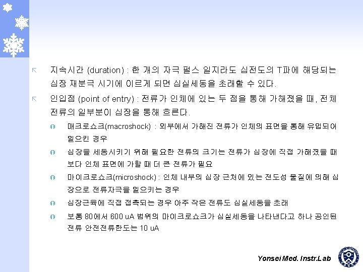
Fibrillation current versus shock duration. Thresholds for ventricular fibrillation in animals for 60 Hz ac current. Duration of current (0. 2 to 5 s) and weight of animal body were varied. (From L. A. Geddes, IEEE Trans. Biomed. Eng. , 1973, 20, 465468. Copyright 1973 by the Institute of Electrical and Electronics Engineers. Reproduced with permission. ) Yonsei Med. Instr. Lab
Effect of entry points on current distribution (a) Macroshock, externally applied current spreads throughout the body. (b) Microshock, all the current applied through an intracardiac catheter flows through the heart. (From F. J. Weibell, "Electrical Safety in the Hospital, " Annals of Biomedical Engineering, 1974, 2, 126 -148. ) Yonsei Med. Instr. Lab
Macroshock due to a ground fault from hot line to equipment cases for (a) ungrounded cases and (b) grounded chassis. Yonsei Med. Instr. Lab
Leakage-current pathways Assume 100 µA of leakage current from the power line to the instrument chassis. (a) Intact ground, and 99. 8 µA flows through the ground. (b) Broken ground, and 100 µA flows through the heart. (c) Broken ground, and 100 µA flows through the heart in the opposite direction. Yonsei Med. Instr. Lab
2. 전기적 안전대책 ã 절연 (isolation) : power & signal ã 접지 (ground) ã 전류 제한 : Fuse, current limit circuit, voltage protection circuit Yonsei Med. Instr. Lab