1 Compact muon radiography system for investigation of

- Slides: 56
1 Compact muon radiography system for investigation of nuclear reactor fuel status LAL seminar May 23, 2013 K. Hara (Univ. of Tsukuba) Period 1&2 data: H. Fujii et al. , Prog. Theor. Exp. Phys. (2013) 073 C 01 Stereo view periods: paper in preparation
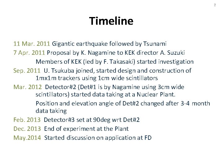
2 Timeline 11 Mar. 2011 Gigantic earthquake followed by Tsunami 7 Apr. 2011 Proposal by K. Nagamine to KEK director A. Suzuki Members of KEK (led by F. Takasaki) started investigation Sep. 2011 U. Tsukuba joined, started design and construction of 1 mx 1 m trackers using 1 cm wide scintillators Mar. 2012 Detector#2 (Det#1 is by Nagamine using 3 cm wide scintillators) started data taking at a Nuclear Plant. Position and elevation angle of Det#2 changed after 3 -4 month data taking Feb. 2013 Detector#3 set at 90 deg wrt Det#2 Dec. 2013 End of experiment at the Plant May. 2014 Started discussion on application at FD
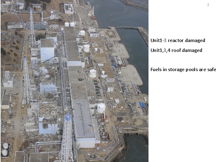
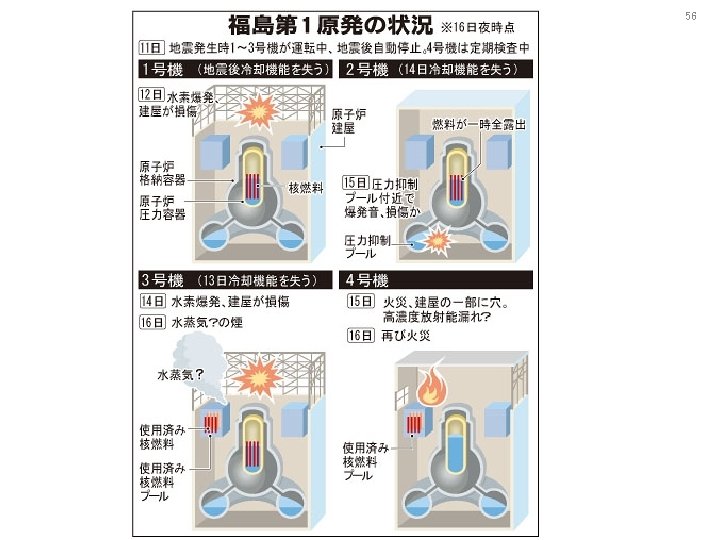
3 Unit 1 -3 reactor damaged Unit 1, 3, 4 roof damaged Fuels in storage pools are safe
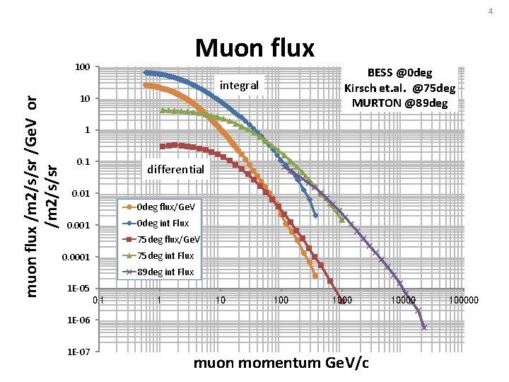
4 Muon flux muon flux /m 2/s/sr /Ge. V or /m 2/s/sr 100 BESS @0 deg Kirsch et. al. @75 deg MURTON @89 deg integral 10 1 0. 1 differential 0. 01 0 deg flux/Ge. V 0 deg int Flux 0. 001 75 deg flux/Ge. V 75 deg int Flux 0. 0001 89 deg int Flux 1 E-05 0. 1 1 10 1000 1 E-06 1 E-07 muon momentum Ge. V/c 100000
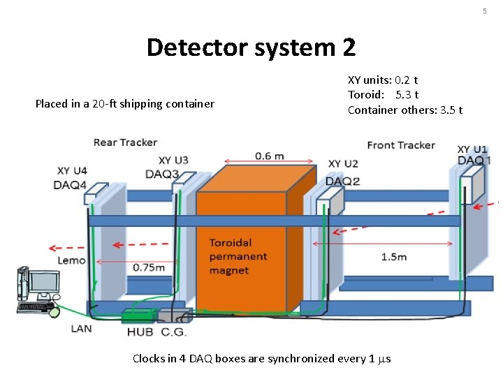
5 Detector system 2 Placed in a 20 -ft shipping container XY units: 0. 2 t Toroid: 5. 3 t Container others: 3. 5 t Clocks in 4 DAQ boxes are synchronized every 1 ms
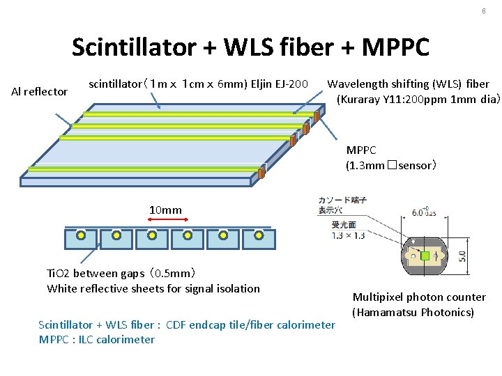
6 Scintillator + WLS fiber + MPPC Al reflector scintillator(1 m x 1 cm x 6 mm) Eljin EJ-200 Wavelength shifting (WLS) fiber (Kuraray Y 11: 200 ppm 1 mm dia) MPPC (1. 3 mm□sensor) 10 mm Ti. O 2 between gaps (0. 5 mm) White reflective sheets for signal isolation Scintillator + WLS fiber : CDF endcap tile/fiber calorimeter MPPC : ILC calorimeter Multipixel photon counter (Hamamatsu Photonics)
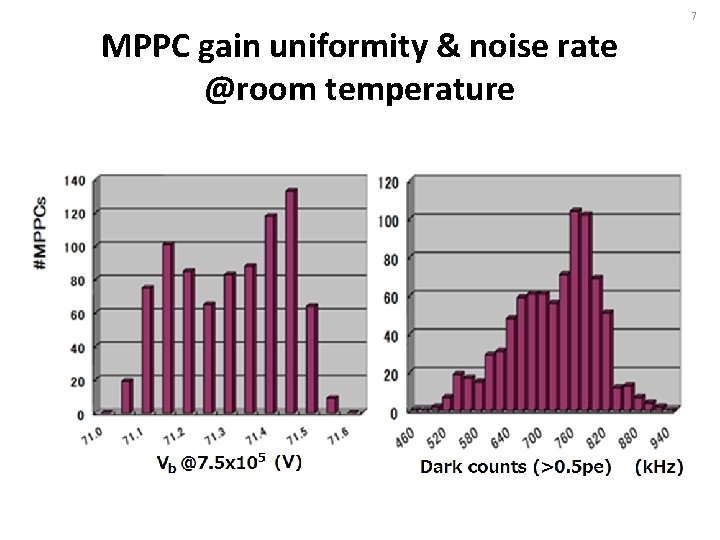
7 MPPC gain uniformity & noise rate @room temperature
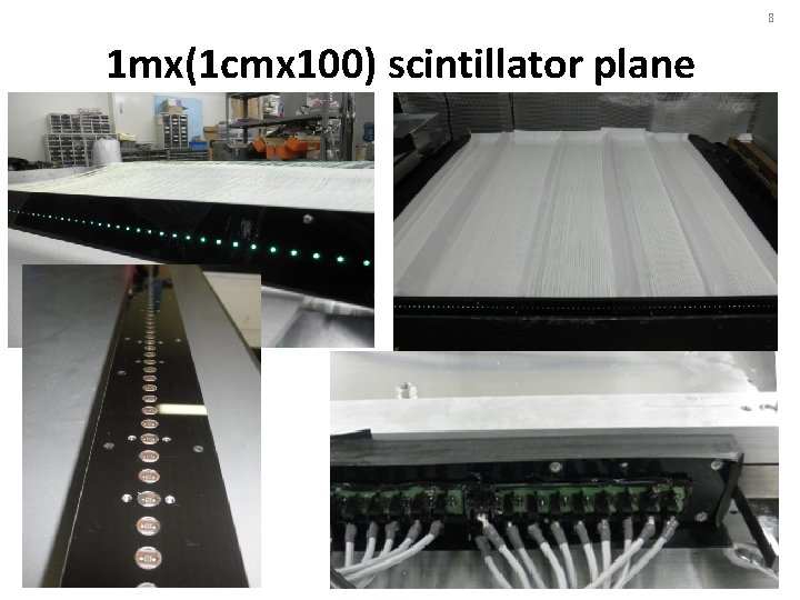
8 1 mx(1 cmx 100) scintillator plane
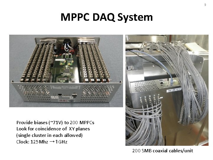
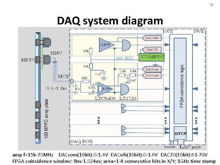
9 MPPC DAQ System Provide biases (~71 V) to 200 MPPCs Look for coincidence of XY planes (single cluster in each allowed) Clock: 125 Mhz →1 GHz 200 SMB coaxial cables/unit
10 DAQ system diagram amp f=15 k-70 MHz DACcom(16 bit): 0 -1. 6 V DACofs(16 bit): 0 -1. 6 V DAC 70(16 bit): 61 -79 V FPGA coincidence window: 8 ns-1. 024 us; area=1 -4 consecutive hits in X/Y; 1 GHz time stamp
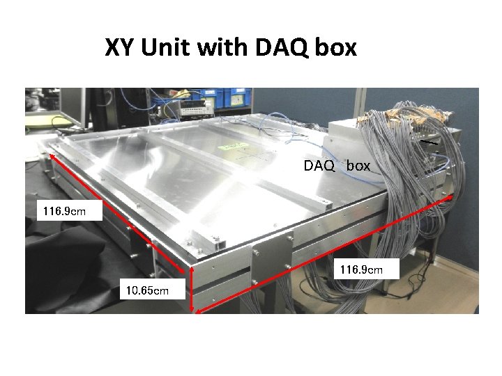
11 XY Unit with DAQ box
XY Unit with DAQ box DAQ box 116. 9 cm 10. 65 cm
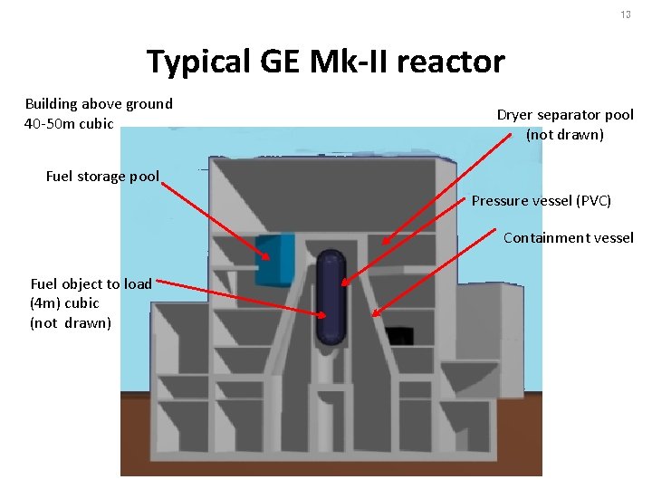
13 Typical GE Mk-II reactor Building above ground 40 -50 m cubic Dryer separator pool (not drawn) Fuel storage pool Pressure vessel (PVC) Containment vessel Fuel object to load (4 m) cubic (not drawn)
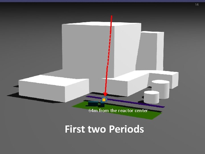
14 64 m from the reactor center First two Periods
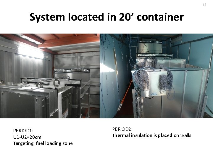
15 System located in 20’ container PERIOD 1: U 1 -U 2=20 cm Targeting fuel loading zone PERIOD 2: Thermal insulation is placed on walls
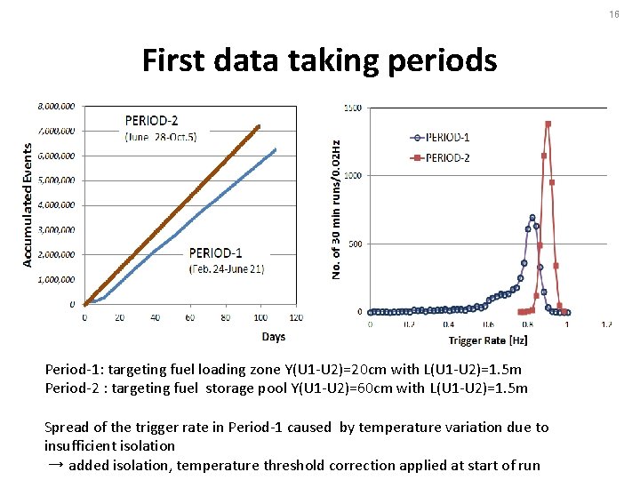
16 First data taking periods Period-1: targeting fuel loading zone Y(U 1 -U 2)=20 cm with L(U 1 -U 2)=1. 5 m Period-2 : targeting fuel storage pool Y(U 1 -U 2)=60 cm with L(U 1 -U 2)=1. 5 m Spread of the trigger rate in Period-1 caused by temperature variation due to insufficient isolation → added isolation, temperature threshold correction applied at start of run
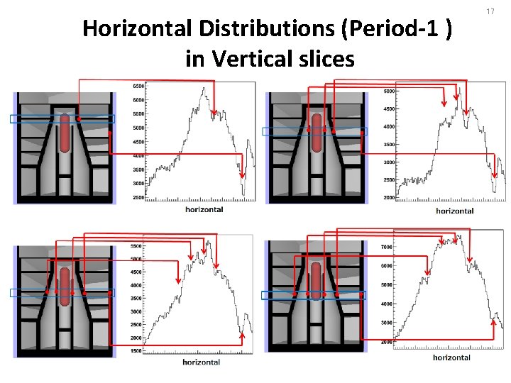
Horizontal Distributions (Period-1 ) in Vertical slices 17
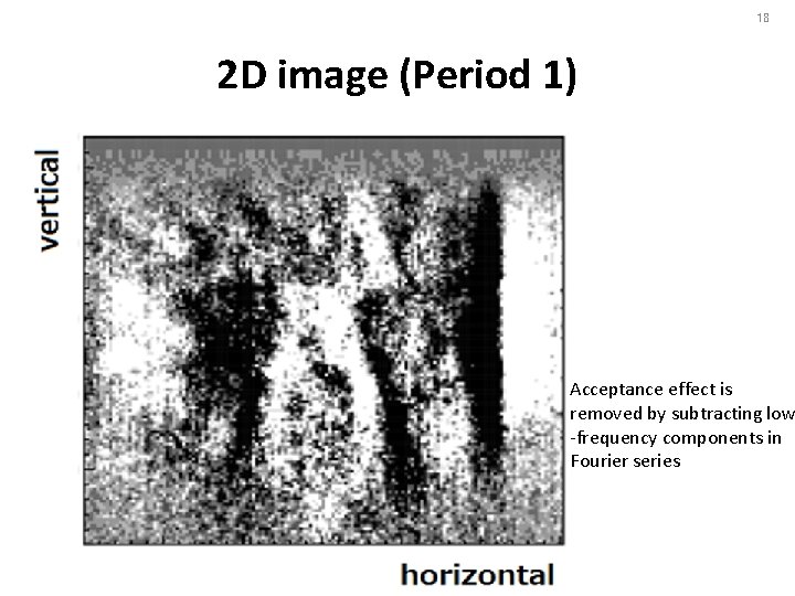
18 2 D image (Period 1) Acceptance effect is removed by subtracting low -frequency components in Fourier series
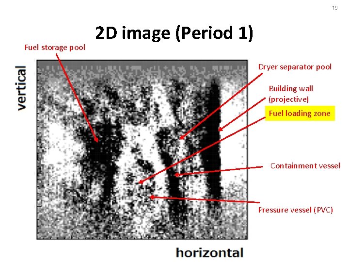
19 Fuel storage pool 2 D image (Period 1) Dryer separator pool Building wall (projective) Fuel loading zone Containment vessel Pressure vessel (PVC)
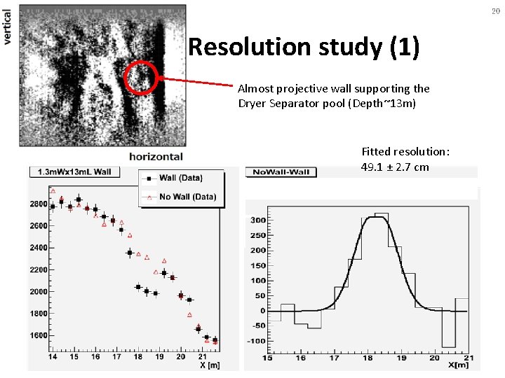
20 Resolution study (1) Almost projective wall supporting the Dryer Separator pool (Depth~13 m) Fitted resolution: 49. 1 ± 2. 7 cm
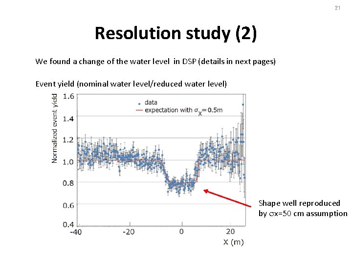
21 Resolution study (2) We found a change of the water level in DSP (details in next pages) Event yield (nominal water level/reduced water level) Shape well reproduced by sx=50 cm assumption
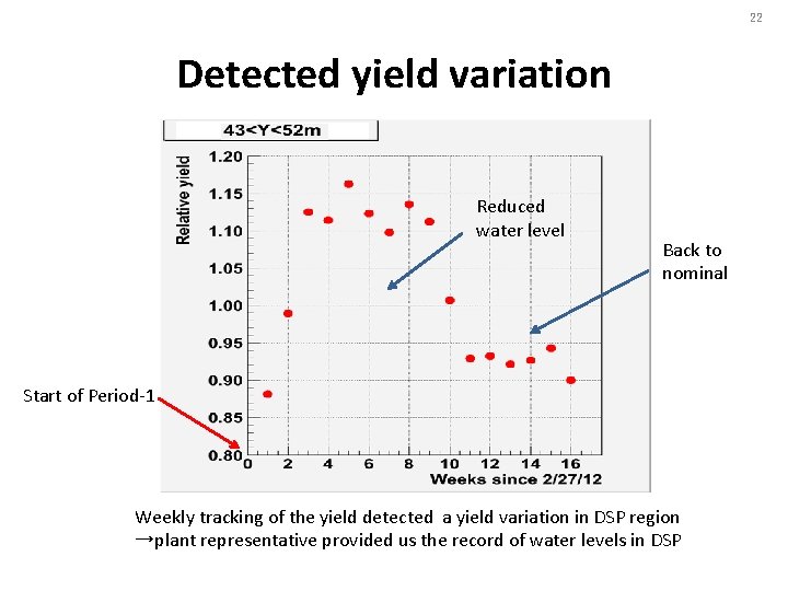
22 Detected yield variation Reduced water level Back to nominal Start of Period-1 Weekly tracking of the yield detected a yield variation in DSP region →plant representative provided us the record of water levels in DSP
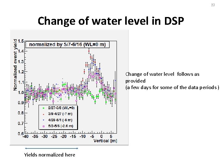
23 Change of water level in DSP Change of water level follows as provided (a few days for some of the data periods ) Yields normalized here
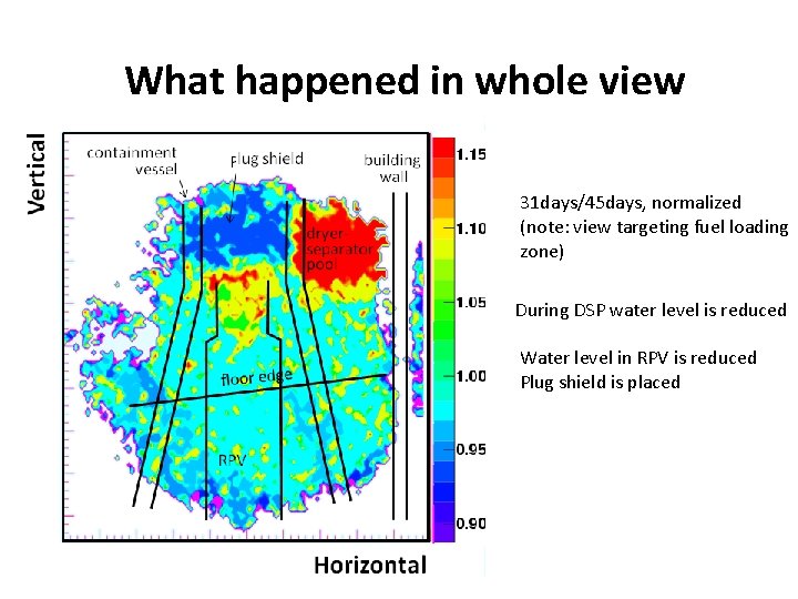
What happened in whole view 31 days/45 days, normalized (note: view targeting fuel loading zone) During DSP water level is reduced Water level in RPV is reduced Plug shield is placed
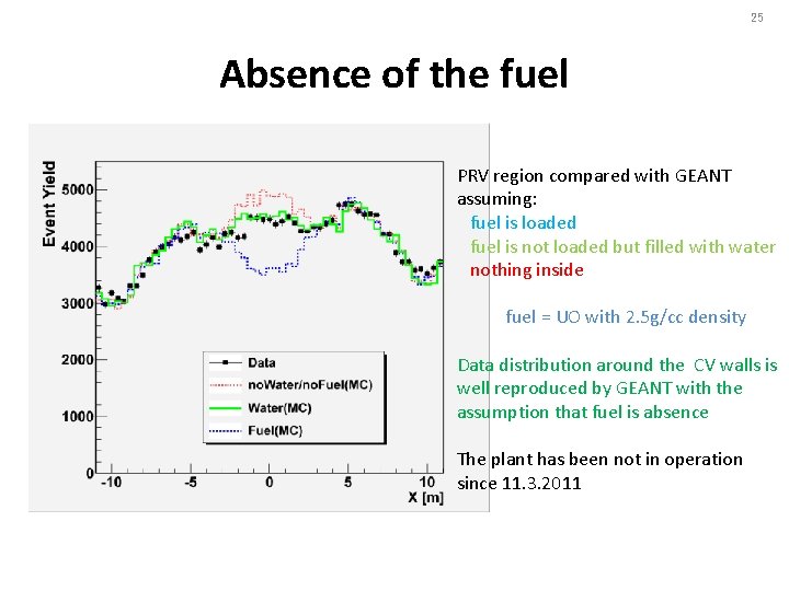
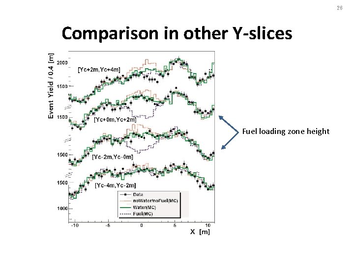
25 Absence of the fuel PRV region compared with GEANT assuming: fuel is loaded fuel is not loaded but filled with water nothing inside fuel = UO with 2. 5 g/cc density Data distribution around the CV walls is well reproduced by GEANT with the assumption that fuel is absence The plant has been not in operation since 11. 3. 2011
26 Comparison in other Y-slices Fuel loading zone height
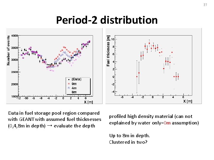
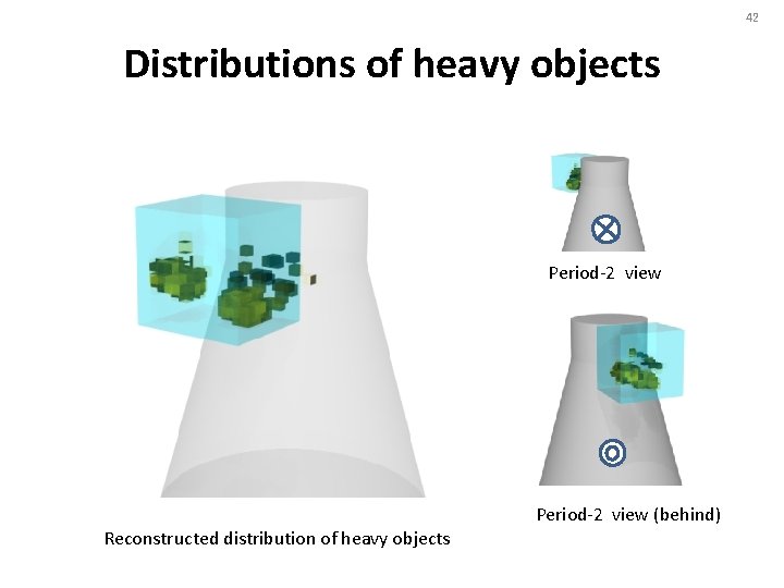
27 Period-2 distribution Data in fuel storage pool region compared with GEANT with assumed fuel thicknesses (0, 4, 8 m in depth) → evaluate the depth profiled high density material (can not explained by water only=0 m assumption) Up to 8 m in depth. Clustered in two?
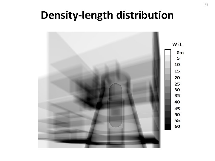
28 Density-length distribution WEL
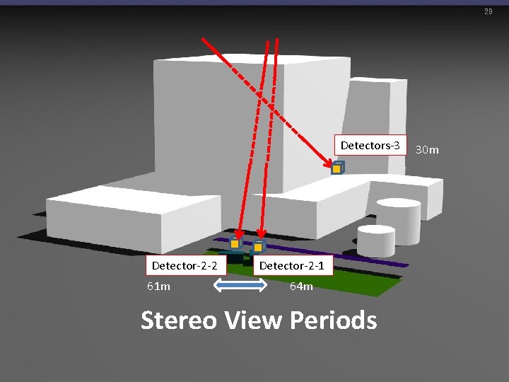
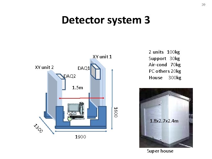
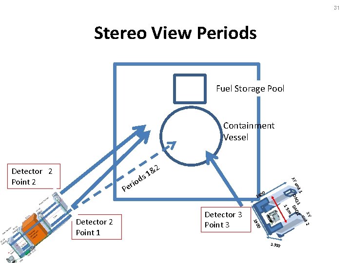
29 Detectors-3 Detector-2 -2 61 m Detector-2 -1 64 m Stereo View Periods 30 m
30 Detector system 3 2 units 100 kg Support 30 kg Air-cond 70 kg PC others 20 kg House 300 kg XY unit 1 XY unit 2 DAQ 1 DAQ 2 1. 5 m 1600 1. 8 x 2. 7 x 2. 4 m 00 13 1900 Super house
31 Stereo View Periods Fuel Storage Pool Containment Vessel 2 1& s iod XY Detector 2 Point 2 0 160 1. 5 0 Detector 3 Point 3 190 Detector 2 Point 1 XY t 2 i un it 1 Q 2 un A A D D m r Pe 1300
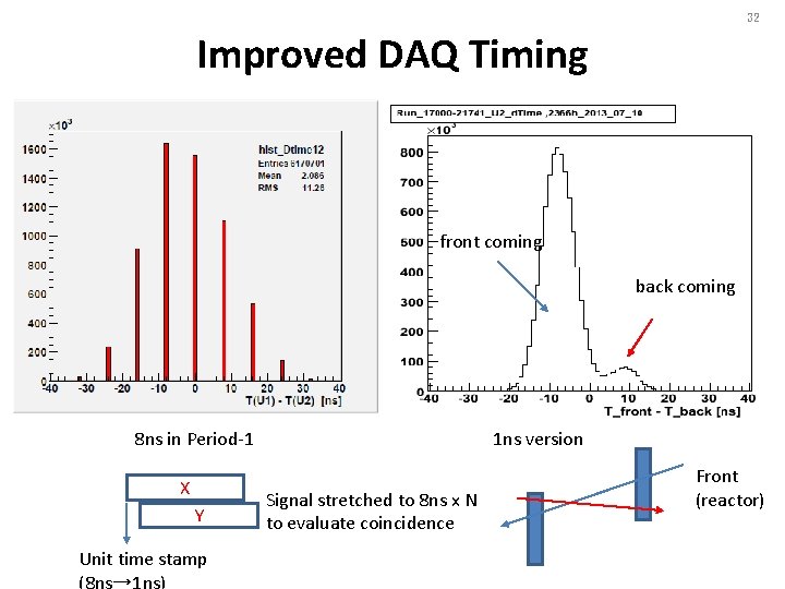
32 Improved DAQ Timing front coming back coming 8 ns in Period-1 X Y Unit time stamp (8 ns→ 1 ns) 1 ns version Signal stretched to 8 ns x N to evaluate coincidence Front (reactor)
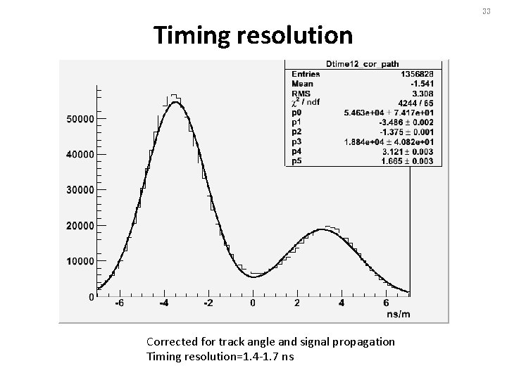
33 Timing resolution Corrected for track angle and signal propagation Timing resolution=1. 4 -1. 7 ns
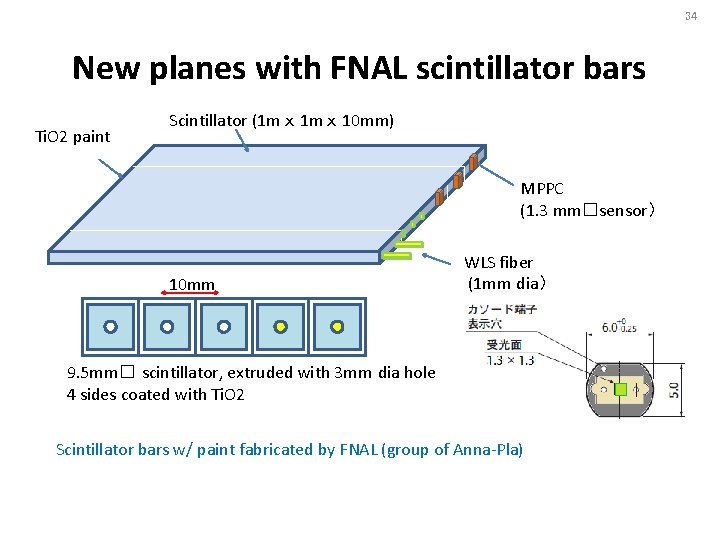
34 New planes with FNAL scintillator bars Ti. O 2 paint Scintillator (1 m x 10 mm) MPPC (1. 3 mm□sensor) 10 mm WLS fiber (1 mm dia) 9. 5 mm□ scintillator, extruded with 3 mm dia hole 4 sides coated with Ti. O 2 Scintillator bars w/ paint fabricated by FNAL (group of Anna-Pla)
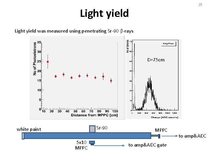
35 Light yield was measured using penetrating Sr-90 b-rays D=75 cm Sr-90 white paint 5 x 10 MPPC to amp&ADC gate to amp&ADC
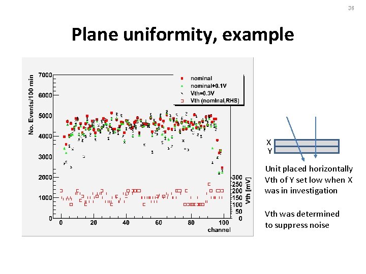
36 Plane uniformity, example X Y Unit placed horizontally Vth of Y set low when X was in investigation Vth was determined to suppress noise
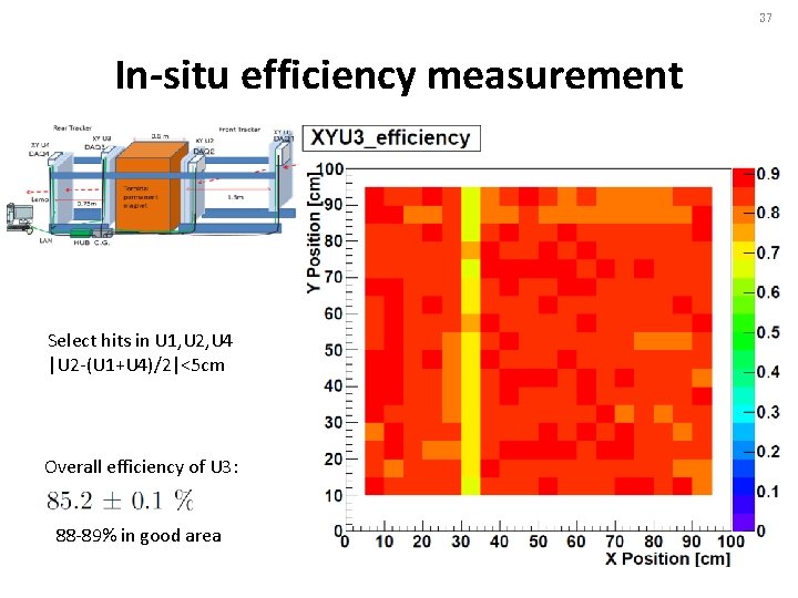
37 In-situ efficiency measurement Select hits in U 1, U 2, U 4 |U 2 -(U 1+U 4)/2|<5 cm Overall efficiency of U 3: 88 -89% in good area
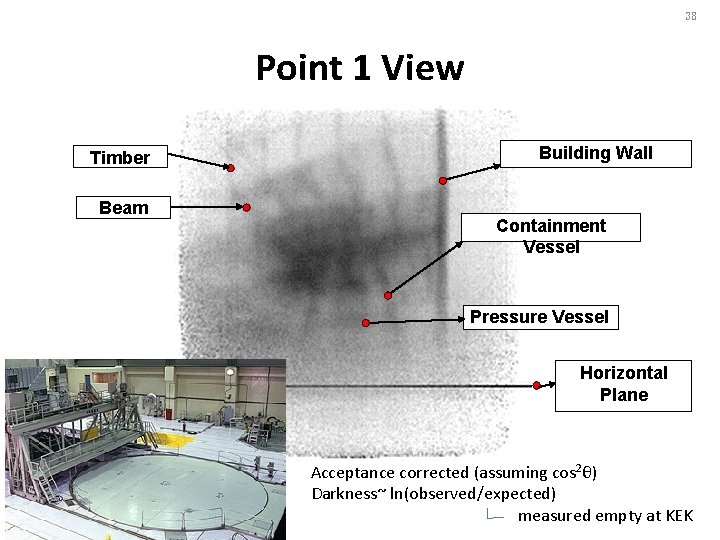
38 Point 1 View Timber Beam Building Wall Containment Vessel Pressure Vessel Horizontal Plane Acceptance corrected (assuming cos 2θ) Darkness~ ln(observed/expected) measured empty at KEK
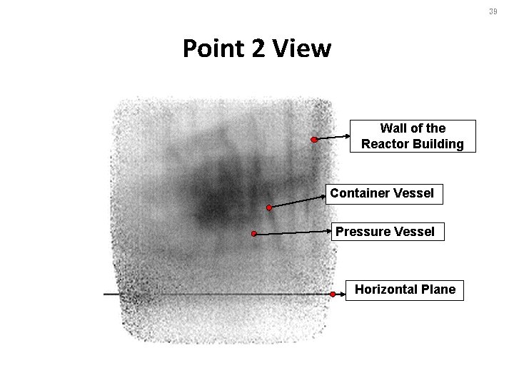
39 Point 2 View Wall of the Reactor Building Container Vessel Pressure Vessel Horizontal Plane
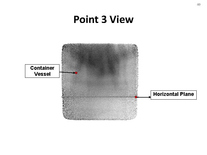
40 Point 3 View Container Vessel Horizontal Plane
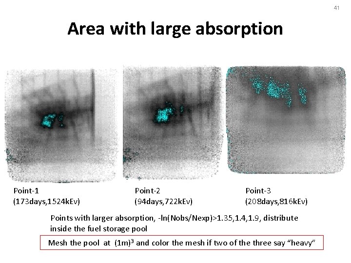
41 Area with large absorption Point-1 (173 days, 1524 k. Ev) Point-2 (94 days, 722 k. Ev) Point-3 (208 days, 816 k. Ev) Points with larger absorption, -ln(Nobs/Nexp)>1. 35, 1. 4, 1. 9, distribute inside the fuel storage pool Mesh the pool at (1 m)3 and color the mesh if two of the three say “heavy”
42 Distributions of heavy objects Period-2 view (behind) Reconstructed distribution of heavy objects
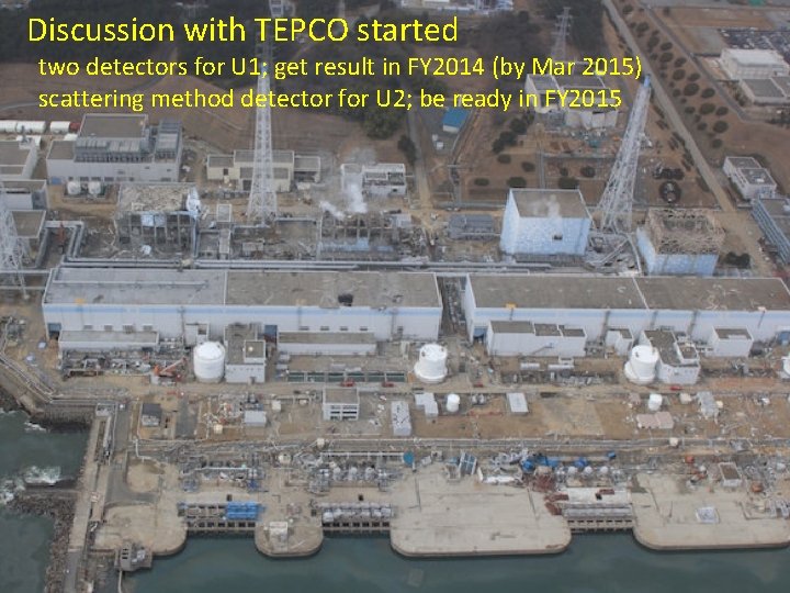
Discussion with TEPCO started two detectors for U 1; get result in FY 2014 (by Mar 2015) scattering method detector for U 2; be ready in FY 2015 43
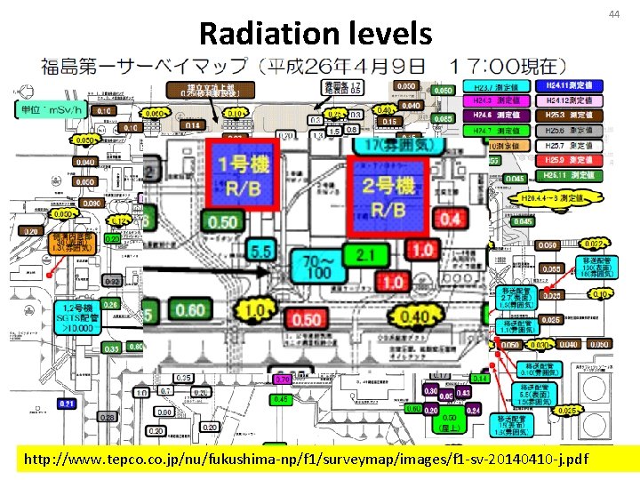
Radiation levels http: //www. tepco. jp/nu/fukushima-np/f 1/surveymap/images/f 1 -sv-20140410 -j. pdf 44
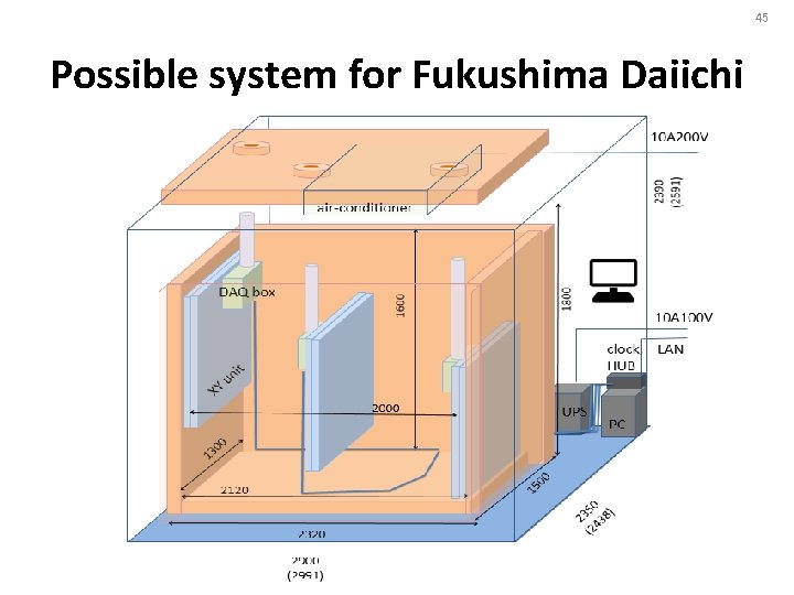
45 Possible system for Fukushima Daiichi
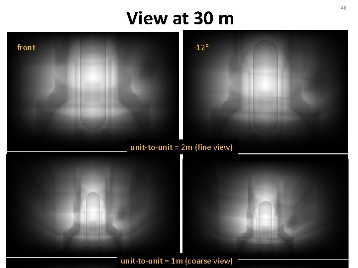
View at 30 m front -12 o unit-to-unit = 2 m (fine view) unit-to-unit = 1 m (coarse view) 46
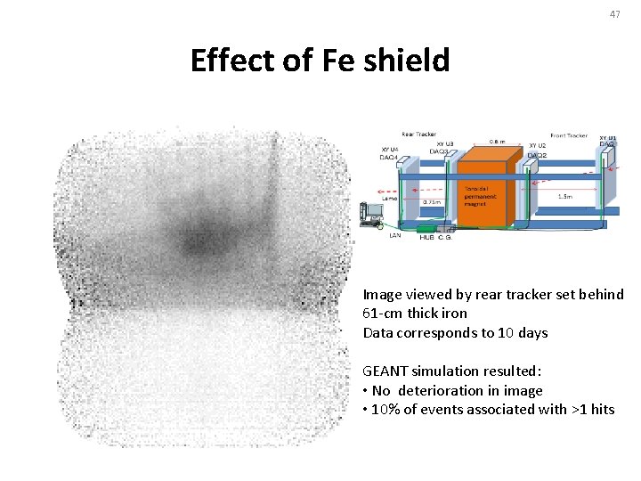
47 Effect of Fe shield Image viewed by rear tracker set behind 61 -cm thick iron Data corresponds to 10 days GEANT simulation resulted: • No deterioration in image • 10% of events associated with >1 hits
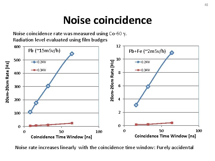
48 Noise coincidence rate was measured using Co-60 g. Radiation level evaluated using film budges 12 Pb (~15 m. Sv/h) 500 20 cm-20 cm Rate [Hz] 600 0. 24 V 0. 34 V 400 300 200 4 0 Coincidence Time Window [ns] 0. 34 V 6 0 100 0. 24 V 8 2 50 Pb+Fe (~2 m. Sv/h) 10 100 0 Pb+Fe 0 50 100 Coincidence Time Window [ns] Noise rate increases linearly with the coincidence time window: Purely accidental
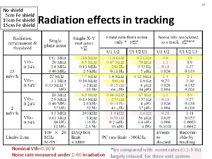
49 No shield 5 cm Fe shield 10 cm Fe shield 15 cm Fe shield Radiation effects in tracking Nominal Vth=0. 30 V Noise rate measured under C-60 irradiation *be compared with event rates (0. 3 -1 Hz) largely relaxed for three unit system
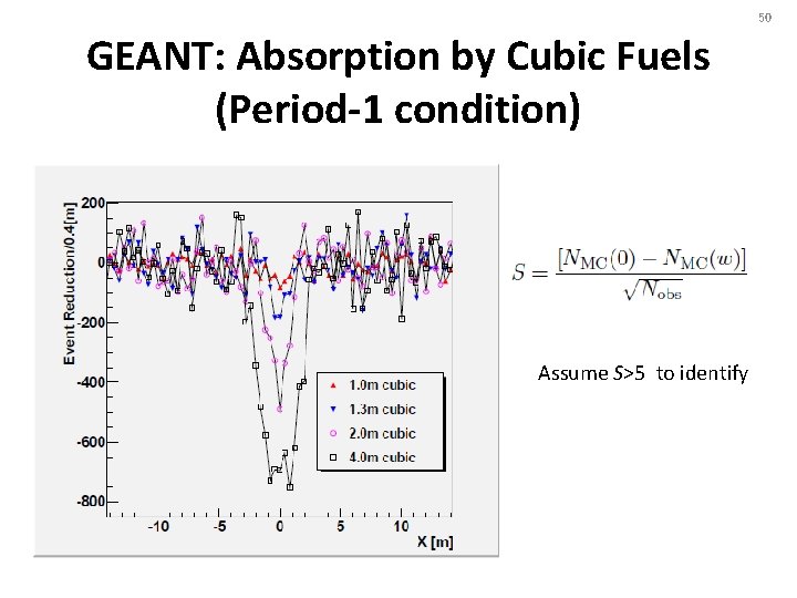
50 GEANT: Absorption by Cubic Fuels (Period-1 condition) Assume S>5 to identify
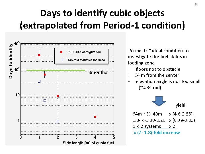
51 Days to identify cubic objects (extrapolated from Period-1 condition) 3 months Period-1: ~ ideal condition to investigate the fuel status in loading zone • floors not to obstacle • 64 m from the center • elevation angle is not too small (~0. 34 rad) yield 64 m->30 -40 m x (4. 6 -2. 56) 0. 34 ->0. 30 -0. 20 x (0. 79 -0. 35) 1 ->2 systems x 2 x (7 - 1. 8)-fold increase
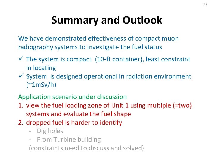
52 Summary and Outlook We have demonstrated effectiveness of compact muon radiography systems to investigate the fuel status ü The system is compact (10 -ft container), least constraint in locating ü System is designed operational in radiation environment (~1 m. Sv/h) Application scenario under discussion 1. view the fuel loading zone of Unit 1 using multiple (=two) systems and evaluate the fuel shape 2. dropped fuel is harder to identify - Dig holes - From Turbine building (constraints need to discuss and solved)
53
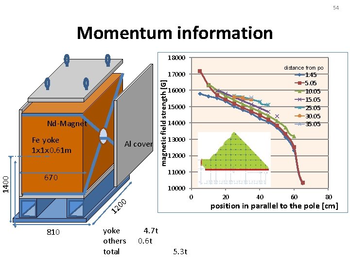
54 magnetic field strength [G] Momentum information position in parallel to the pole [cm]
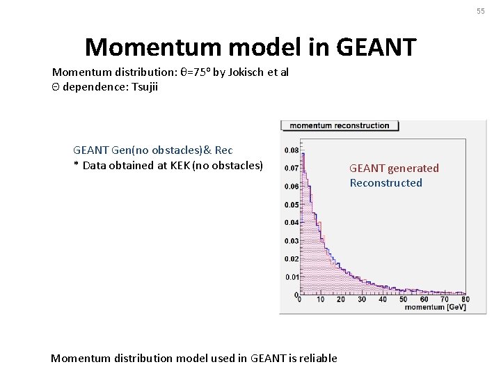
55 Momentum model in GEANT Momentum distribution: θ=75 o by Jokisch et al Θ dependence: Tsujii GEANT Gen(no obstacles)& Rec * Data obtained at KEK (no obstacles) Momentum distribution model used in GEANT is reliable GEANT generated Reconstructed
56