Using GIS Intro to Spatial Reference Part 2
- Slides: 59
------Using GIS-- Intro to Spatial Reference, Part 2 By Austin Troy
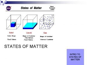
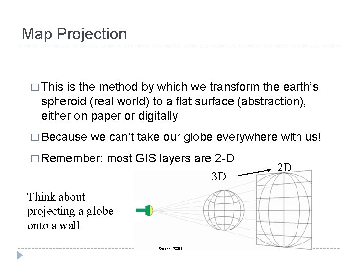
Map Projection � This is the method by which we transform the earth’s spheroid (real world) to a flat surface (abstraction), either on paper or digitally � Because we can’t take our globe everywhere with us! � Remember: most GIS layers are 2 -D 3 D Think about projecting a globe onto a wall Source: ESRI 2 D
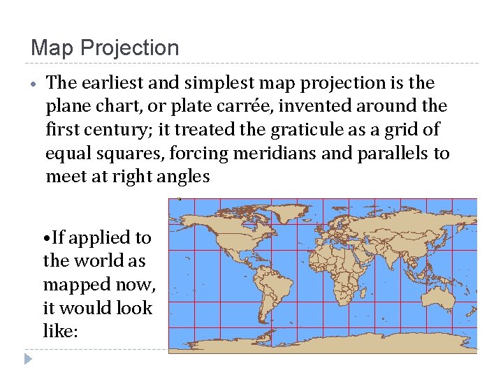
Map Projection • The earliest and simplest map projection is the plane chart, or plate carrée, invented around the first century; it treated the graticule as a grid of equal squares, forcing meridians and parallels to meet at right angles • If applied to the world as mapped now, it would look like:
Map Projection: Distortion �By definition, projections distorts: • Shape • Area • Distance • Direction �Some projections specialize in preserving one or several of these features, but none preserve all
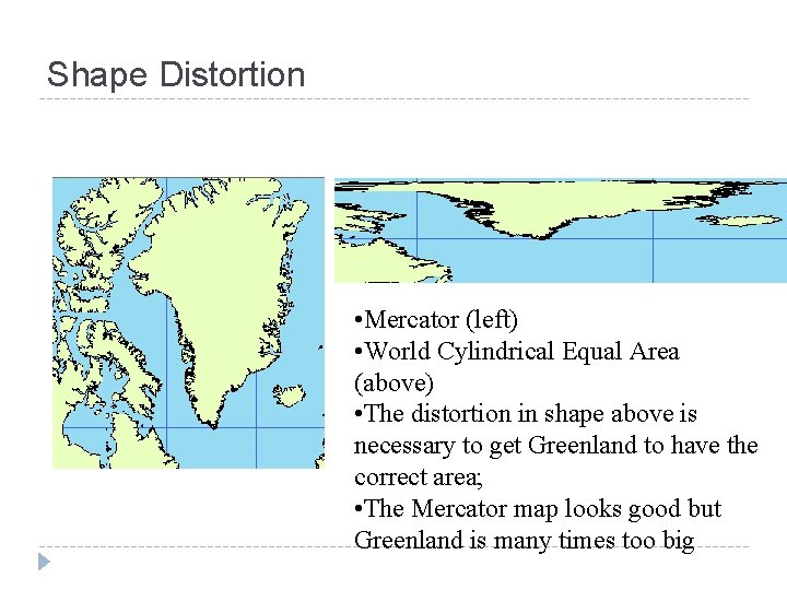
Shape Distortion � Shape: projection can distort the shape of a feature. Conformal maps preserve the shape of smaller, local geographic features, while general shapes of larger features are distorted. That is, they preserve local angles; angle on map will be same as angle on globe. Conformal maps also preserve constant scale locally.
Shape Distortion • Mercator (left) • World Cylindrical Equal Area (above) • The distortion in shape above is necessary to get Greenland to have the correct area; • The Mercator map looks good but Greenland is many times too big
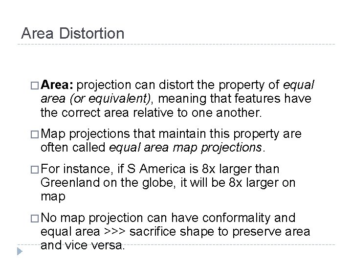
Area Distortion � Area: projection can distort the property of equal area (or equivalent), meaning that features have the correct area relative to one another. � Map projections that maintain this property are often called equal area map projections. � For instance, if S America is 8 x larger than Greenland on the globe, it will be 8 x larger on map � No map projection can have conformality and equal area >>> sacrifice shape to preserve area and vice versa.
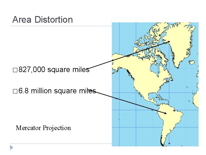
Area Distortion � 827, 000 � 6. 8 square miles million square miles Mercator Projection
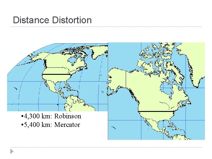
Distance Distortion � Distance: projection can distort measures of true distance. Accurate distance is maintained for only certain parallels or meridians unless the map is localized. Maps are said to be equidistant if distance from the map projection's center to all points is accurate.
Distance Distortion • 4, 300 km: Robinson • 5, 400 km: Mercator
Direction Distortion � Direction: projection can distort true directions between geographic locations; that is, it can mess up the angle, or azimuth between two features. Some azimuthal map projections maintain the correct azimuth between any two points. In a map of this kind, the angle of a line drawn between any two locations on the projection gives the correct direction with respect to true north.
Map Projection: Distortion � When choosing a projection, one must take into account what it is that matters in your analysis and what properties you need to preserve. � Conformal and equal area properties are mutually exclusive but some map projections can have more than one preserved property. For instance a map can be conformal and azimuthal. � Conformal and equal area properties are global (apply to whole map) while equidistant and azimuthal properties are local and may be true only from or to the center of map.
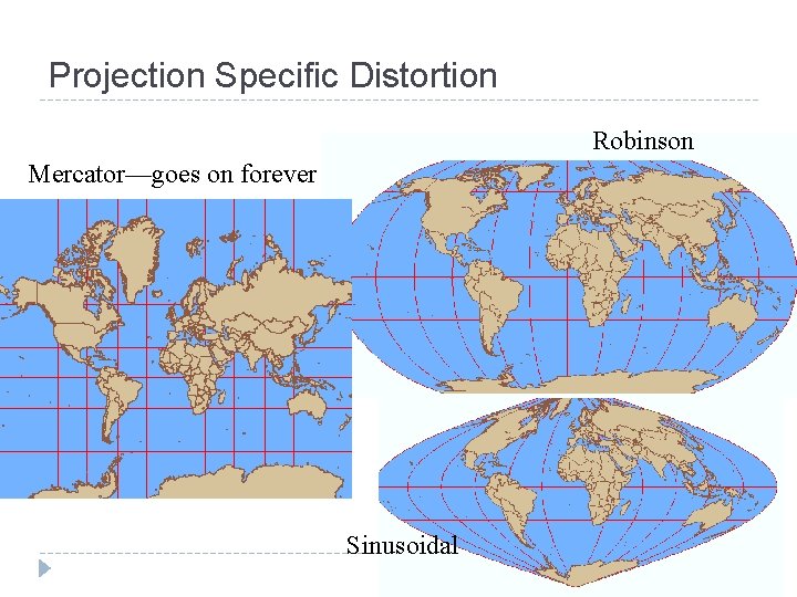
Projection Specific Distortion � Mercator maintains shape and direction, but sacrifices area accuracy. � The Sinusoidal and Equal-Area Cylindrical projections both maintain area, but look quite different from each other. The latter distorts shape. � The Robinson projection does not enforce any specific properties but is widely used because it makes the earth’s surface and its features look somewhat accurate.
Projection Specific Distortion Robinson Mercator—goes on forever Sinusoidal
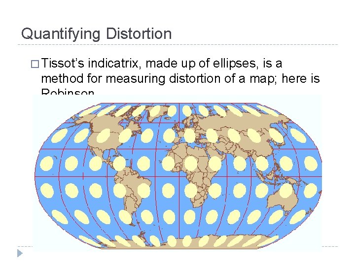
Quantifying Distortion � Tissot’s indicatrix, made up of ellipses, is a method for measuring distortion of a map; here is Robinson
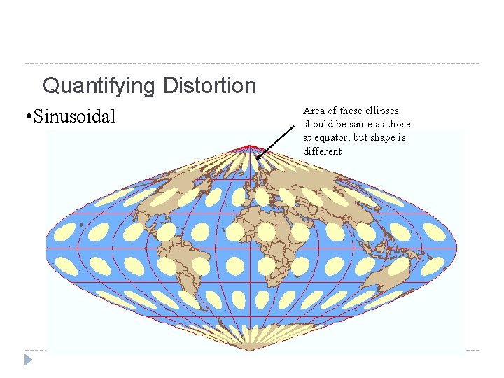
Quantifying Distortion • Sinusoidal Area of these ellipses should be same as those at equator, but shape is different
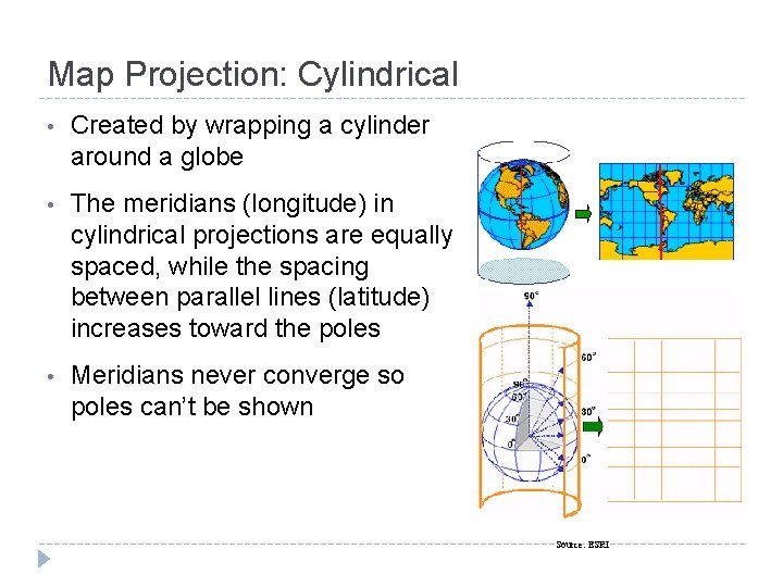
Map Projection: Cylindrical • Created by wrapping a cylinder around a globe • The meridians (longitude) in cylindrical projections are equally spaced, while the spacing between parallel lines (latitude) increases toward the poles • Meridians never converge so poles can’t be shown Source: ESRI
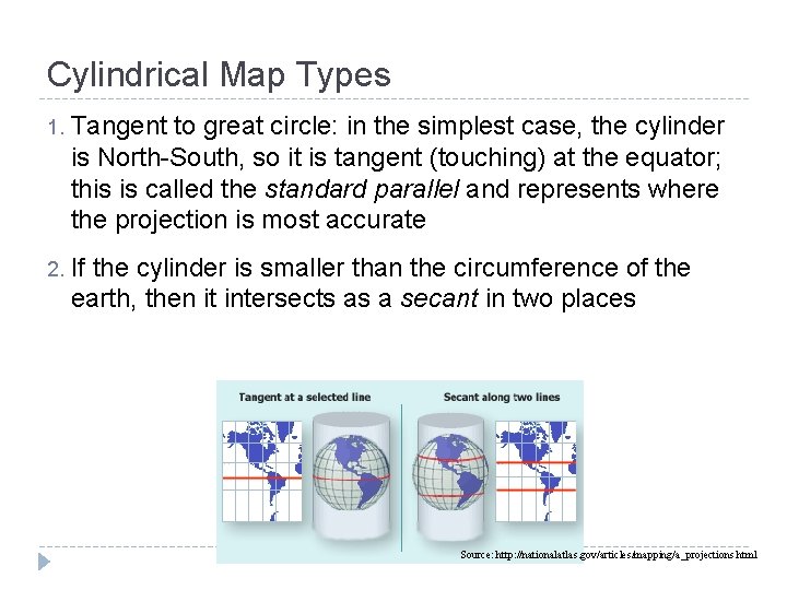
Cylindrical Map Types 1. Tangent to great circle: in the simplest case, the cylinder is North-South, so it is tangent (touching) at the equator; this is called the standard parallel and represents where the projection is most accurate 2. If the cylinder is smaller than the circumference of the earth, then it intersects as a secant in two places Source: http: //nationalatlas. gov/articles/mapping/a_projections. html
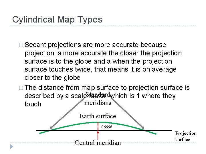
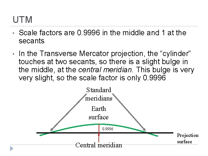
Cylindrical Map Types � Secant projections are more accurate because projection is more accurate the closer the projection surface is to the globe and a when the projection surface touches twice, that means it is on average closer to the globe � The distance from map surface to projection surface is described by a scale. Standard factor, which is 1 where they meridians touch Earth surface 0. 9996 Central meridian Projection surface
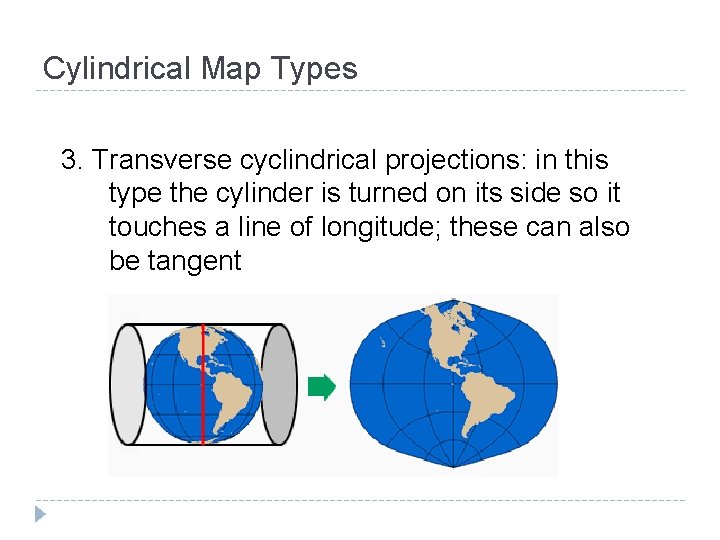
Cylindrical Map Types 3. Transverse cyclindrical projections: in this type the cylinder is turned on its side so it touches a line of longitude; these can also be tangent
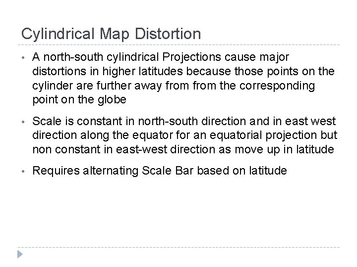
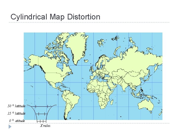
Cylindrical Map Distortion • A north-south cylindrical Projections cause major distortions in higher latitudes because those points on the cylinder are further away from the corresponding point on the globe • Scale is constant in north-south direction and in east west direction along the equator for an equatorial projection but non constant in east-west direction as move up in latitude • Requires alternating Scale Bar based on latitude
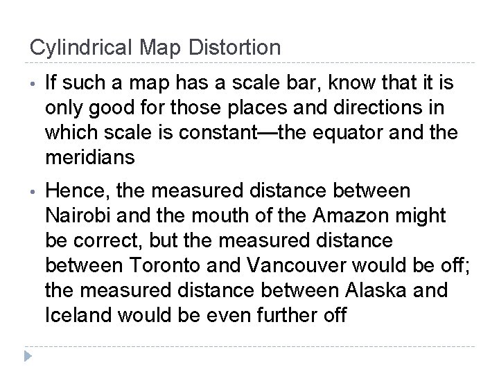
Cylindrical Map Distortion • If such a map has a scale bar, know that it is only good for those places and directions in which scale is constant—the equator and the meridians • Hence, the measured distance between Nairobi and the mouth of the Amazon might be correct, but the measured distance between Toronto and Vancouver would be off; the measured distance between Alaska and Iceland would be even further off
Cylindrical Map Distortion ◦ latitude 25 ◦ latitude 0 ◦ atitude 50 X miles
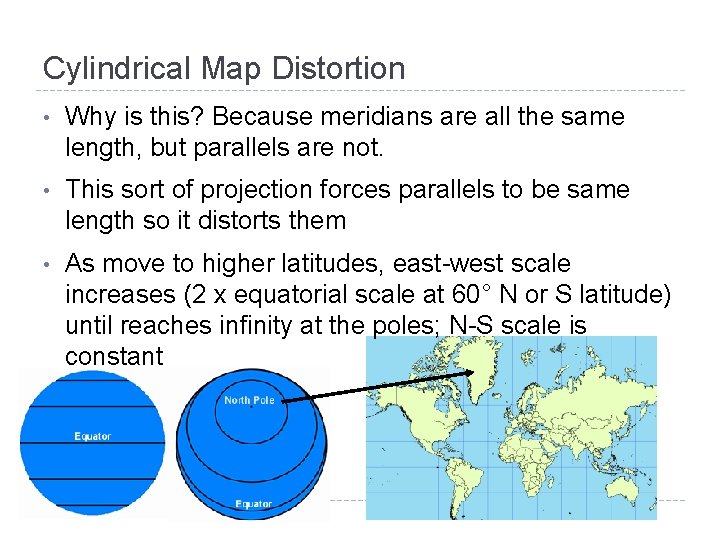
Cylindrical Map Distortion • Why is this? Because meridians are all the same length, but parallels are not. • This sort of projection forces parallels to be same length so it distorts them • As move to higher latitudes, east-west scale increases (2 x equatorial scale at 60° N or S latitude) until reaches infinity at the poles; N-S scale is constant
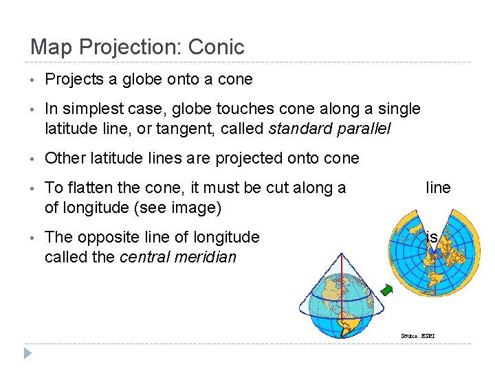
Map Projection: Conic • Projects a globe onto a cone • In simplest case, globe touches cone along a single latitude line, or tangent, called standard parallel • Other latitude lines are projected onto cone • To flatten the cone, it must be cut along a of longitude (see image) line • The opposite line of longitude called the central meridian is Source: ESRI
Map Projection: Conic • Is most accurate where globe and cone meet—at the standard parallel • Distortion generally increases north or south of it, so poles are often not included • Conic projections are typically used for midlatitude zones with east-to-west orientation. They are normally applied only to portions of a hemisphere (e. g. North America)
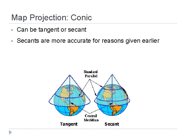
Map Projection: Conic • Can be tangent or secant • Secants are more accurate for reasons given earlier
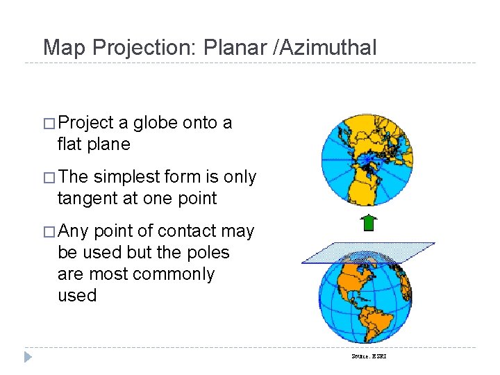
Map Projection: Planar /Azimuthal � Project a globe onto a flat plane � The simplest form is only tangent at one point � Any point of contact may be used but the poles are most commonly used Source: ESRI
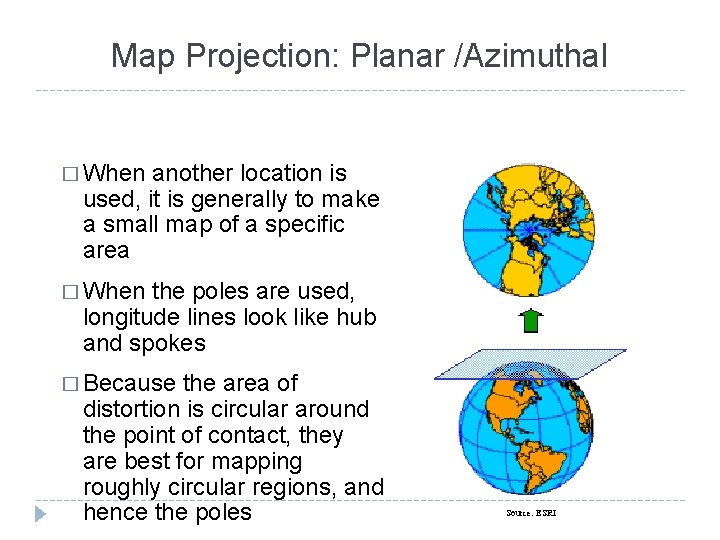
Map Projection: Planar /Azimuthal � When another location is used, it is generally to make a small map of a specific area � When the poles are used, longitude lines look like hub and spokes � Because the area of distortion is circular around the point of contact, they are best for mapping roughly circular regions, and hence the poles Source: ESRI
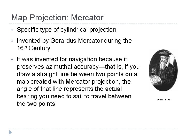
Map Projection: Mercator • Specific type of cylindrical projection • Invented by Gerardus Mercator during the 16 th Century • It was invented for navigation because it preserves azimuthal accuracy—that is, if you draw a straight line between two points on a map created with Mercator projection, the angle of that line represents the actual bearing you need to sail to travel between the two points Source: ESRI
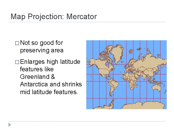
Map Projection: Mercator � Not so good for preserving area � Enlarges high latitude features like Greenland & Antarctica and shrinks mid latitude features.
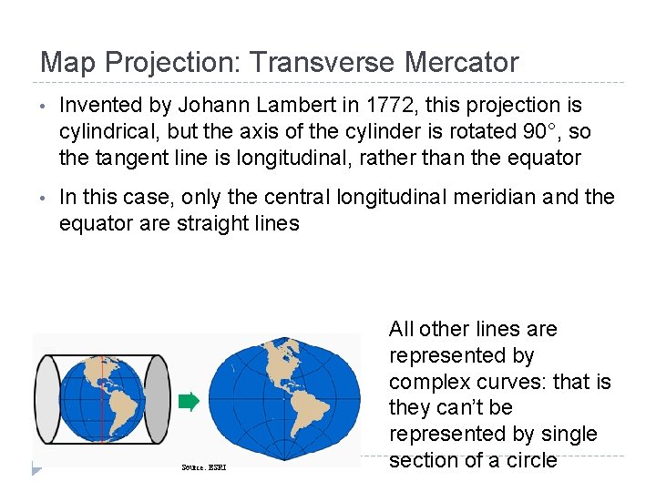
Map Projection: Transverse Mercator • Invented by Johann Lambert in 1772, this projection is cylindrical, but the axis of the cylinder is rotated 90°, so the tangent line is longitudinal, rather than the equator • In this case, only the central longitudinal meridian and the equator are straight lines Source: ESRI All other lines are represented by complex curves: that is they can’t be represented by single section of a circle
Map Projection: Transverse Mercator �Transverse Mercator projection is not used on a global scale but is applied to regions that have a general north-south orientation, while Mercator tends to be used more for geographic features with east-west axis. �Commonly used in the US with the State Plane Coordinate system, with north-south features
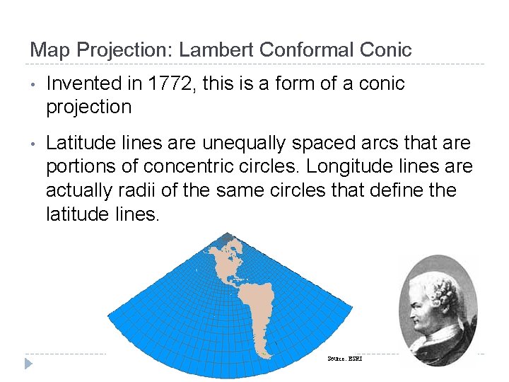
Map Projection: Lambert Conformal Conic • Invented in 1772, this is a form of a conic projection • Latitude lines are unequally spaced arcs that are portions of concentric circles. Longitude lines are actually radii of the same circles that define the latitude lines. Source: Lecture materials by Austin Troy © 2008, except where noted. ESRI
Map Projection: Lambert Conformal Conic � Very good for middle latitudes with east-west orientation. � It portrays the pole as a point � It portrays shape more accurately than area and is commonly used for North America. � The State Plane coordinate system uses it for eastwest oriented features
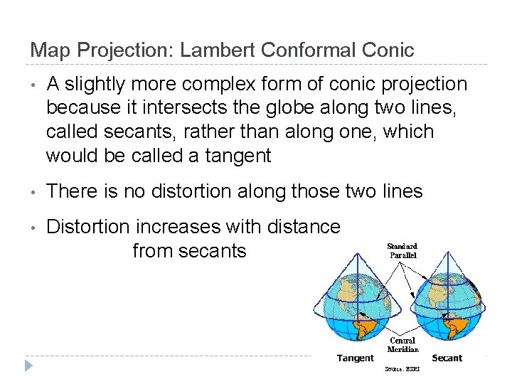
Map Projection: Lambert Conformal Conic • A slightly more complex form of conic projection because it intersects the globe along two lines, called secants, rather than along one, which would be called a tangent • There is no distortion along those two lines • Distortion increases with distance from secants Source: ESRI
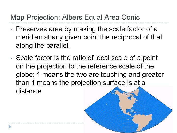
Map Projection: Albers Equal Area Conic • Developed by Heinrich Christian Albers in the early nineteenth century for European maps • Conic projection, using secants as standard parallels • Differences between Albers and Lambert • Lambert preserves shape Albers preserves area • Poles are not represented as points, but as arcs, meaning that meridians don’t converge • Latitude lines are unequally spaced concentric circles, whose spacing decreases toward the poles. • Useful for portraying large land units, like Alaska or all 48 states
Map Projection: Albers Equal Area Conic • Preserves area by making the scale factor of a meridian at any given point the reciprocal of that along the parallel. • Scale factor is the ratio of local scale of a point on the projection to the reference scale of the globe; 1 means the two are touching and greater than 1 means the projection surface is at a distance
Other Selected Projections • More Cylindrical equal area: (have straight meridians and parallels, the meridians are equally spaced, the parallels unequally spaced) • Behrmann cyclindrical equal-area: single standard parallel at 30 ° north • Gall’s stereographic: secant intersecting at 45° north and 45 ° south • Peter’s: de-emphasizes area exaggerations in high latitudes; standard parallels at 45 or 47 ° Thanks to Peter Dana, The Geographer's Craft Project, Department of Geography, The University of Colorado at Boulder for links
Other Selected Projections Azimuthal projections: • • Azimuthal equidistant: preserves distance property; used to show air route distances • Lambert Azimuthal equal area: Often used for polar regions; central meridian is straight, others are curved • Oblique Aspect Orthographic • North Polar Stereographic Thanks to Peter Dana, The Geographer's Craft Project, Department of Geography, The University of Colorado at Boulder for links
Other Selected Projections More conic projections • • Equidistant Conic: used for showing areas near to, but on one side of the equator, preserves only distance property • Polyconic: used for most of the early USGS quads; based on an infinite number of cones tangent to an infinite number of parallels; central meridian straight but other lines are complex curves Thanks to Peter Dana, The Geographer's Craft Project, Department of Geography, The University of Colorado at Boulder for links
Other Selected Projections • Pseudo-cylindrical projections: resemble cylindrical projections, with straight, parallels and equally spaced meridians, but all meridians but the reference meridian are curves • Mollweide: used for world maps; is equal-area; 90 th meridians are semi-circles • Robinson: based on tables of coordinates, not mathematical formulas; distorts shape, area, scale, and distance in an attempt to make a balanced map Thanks to Peter Dana, The Geographer's Craft Project, Department of Geography, The University of Colorado at Boulder for links
Coordinate Systems • Map projections provide the means for viewing small-scale maps, such as maps of the world or a continent or country (1: 1, 000 or smaller) • Plane coordinate systems are typically used for much larger-scale mapping (1: 100, 000 or bigger)
Coordinate Systems • Projections are designed to minimize distortions of the four properties we talked about, because as scale decreases, error increases • Coordinate systems are more about accurate positioning (relative and absolute positioning) • To maintain their accuracy, coordinate systems are generally divided into zones where each zone is based on a separate
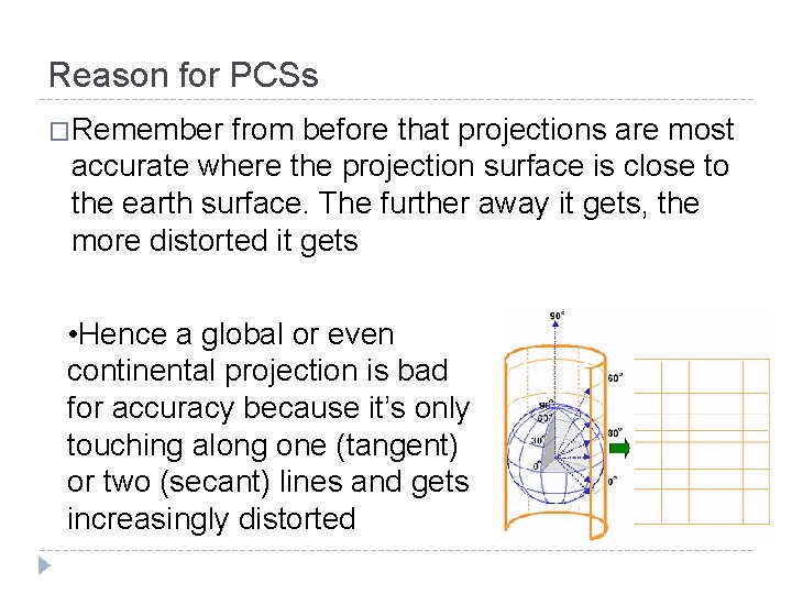
Reason for PCSs �Remember from before that projections are most accurate where the projection surface is close to the earth surface. The further away it gets, the more distorted it gets • Hence a global or even continental projection is bad for accuracy because it’s only touching along one (tangent) or two (secant) lines and gets increasingly distorted
Reason for PCSs • Plane coordinate systems get around this by breaking the earth up into zones where each zone has its own projection center and projection. • The more zones there and the smaller each zone, the more accurate the resulting projections • This serves to minimize the scale factor, or distance between projection surface and earth surface to an acceptable level
Coordinate Systems • The four most commonly used coordinate systems in the US: • Universal Transverse Mercator (UTM) grid system • State Plane Coordinate System (SPC) • Others: • The Universal Polar Stereographic (UPS) grid system • The Public Land Survey System (PLSS)
UTM • Universal Transverse Mercator • UTM is based on the Transverse Mercator projection (remember, that’s using a cylinder turned on its side) • It generally uses either the NAD 27 or NAD 83 datums, so you will often see a layer as projected in “UTM 83” or “UTM 27” • UTM is used for large scale mapping applications the world over, when the unit of analysis is fairly small, like a state
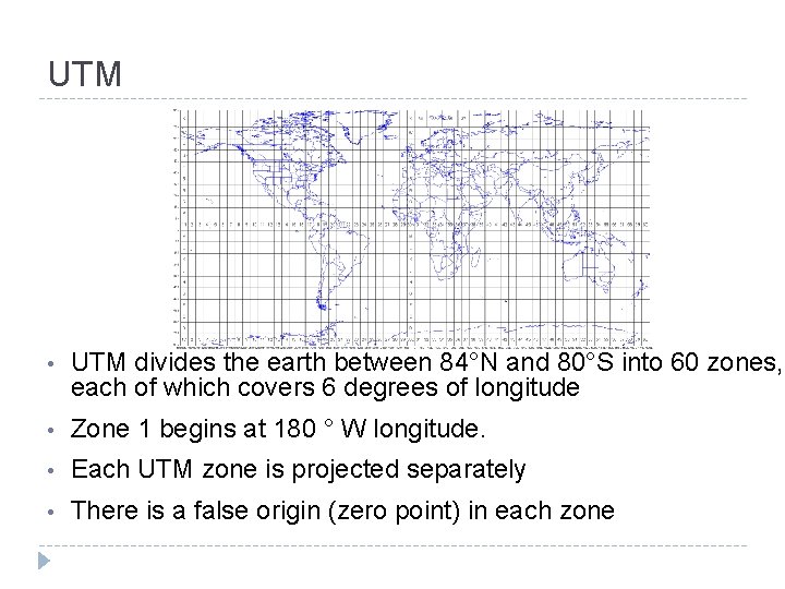
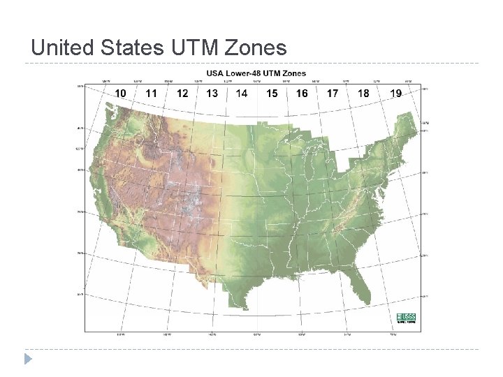
UTM • UTM divides the earth between 84°N and 80°S into 60 zones, each of which covers 6 degrees of longitude • Zone 1 begins at 180 ° W longitude. • Each UTM zone is projected separately • There is a false origin (zero point) in each zone
United States UTM Zones
UTM • Scale factors are 0. 9996 in the middle and 1 at the secants • In the Transverse Mercator projection, the “cylinder” touches at two secants, so there is a slight bulge in the middle, at the central meridian. This bulge is very slight, so the scale factor is only 0. 9996 Standard meridians Earth surface 0. 9996 Central meridian Projection surface
UTM • In the northern hemisphere, coordinates are measured from a false origin at the equator and 500, 000 meters west of the central meridian • In the southern hemisphere, coordinates are measured from a false origin 10, 000 meters south of the equator and 500, 000 meters west of the central meridian • Accuracy: 1 in 2, 500
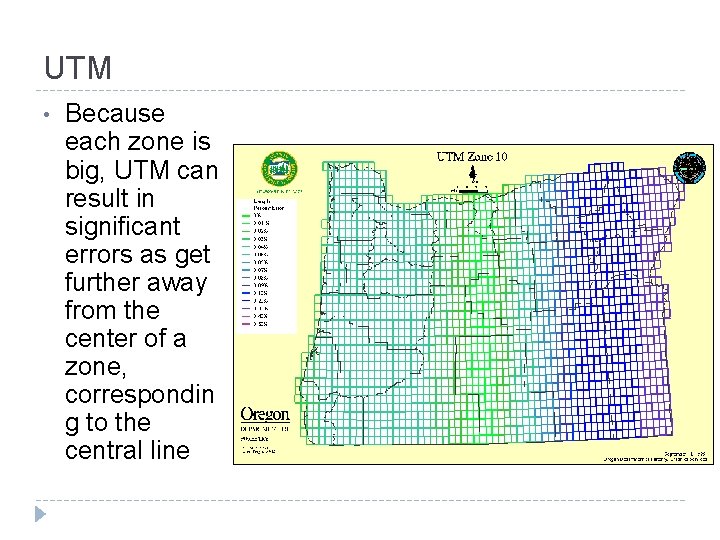
UTM • Because each zone is big, UTM can result in significant errors as get further away from the center of a zone, correspondin g to the central line
SPC System • State Plane Coordinate System is one of the most common coordinate systems in use in the US • It was developed in the 1930 s to record original land survey monument locations in the US • More accurate than UTM, with required accuracy of 1 part in 10, 000 • Zones are much smaller—many states have two or more zones
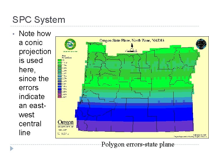
SPC System • Transverse Mercator projection is used for zones that have a north south access. • Lambert conformal conic is used for zones that are elongated in the east-west direction. Why? • Units of measurement are feet, which are measured from a false origin. • SPC maps are found based on both NAD 27 and NAD 83, like with UTM, but SPC 83 is in meters, while SPC 27 is in feet
SPC System • Many States have their own version of SPC • Vermont has the Vermont State Plane Coordinate System, which is in meters and based on NAD 83 • In 1997, VCGI converted all their data from SPC 27 to SPC 83 • Vermont uses Transverse Mercator because of its north-south orientation
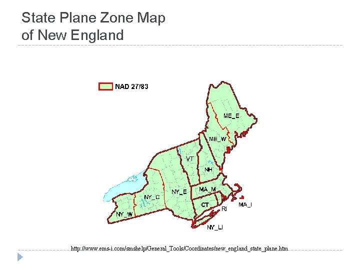
State Plane Zone Map of New England http: //www. ems-i. com/smshelp/General_Tools/Coordinates/new_england_state_plane. htm
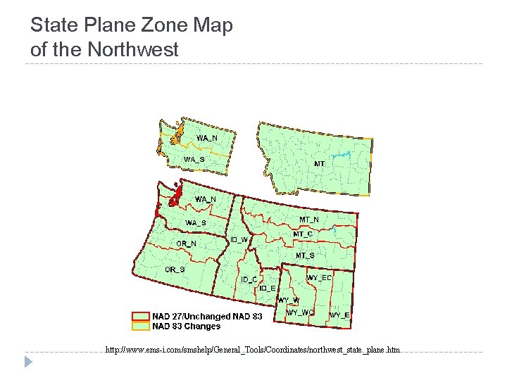
State Plane Zone Map of the Northwest http: //www. ems-i. com/smshelp/General_Tools/Coordinates/northwest_state_plane. htm
SPC System • Note how a conic projection is used here, since the errors indicate an eastwest central line Polygon errors-state plane