Basic Concepts Chapter 1 1 2 1 3


Basic Concepts - Chapter 1 1. 2 1. 3 1. 4 1. 5 1. 6 Systems of Units. Electric Charge. Current. Voltage. Power and Energy. Circuit Elements. 2
 Six basic units Quantity Length Mass Time Electric")
1. 1 System of Units (1) Six basic units Quantity Length Mass Time Electric current Thermodynamic temperature Luminous intensity Basic unit meter kilogram second ampere kelvin Symbol m Kg s A K candela cd 3
 The derived units commonly used in electric circuit")
1. 1 System of Units (2) The derived units commonly used in electric circuit theory Decimal multiples and submultiples of SI units 4

1. 2 Electric Charges • Charge is an electrical property of the atomic particles of which matter consists, measured in coulombs (C). • The charge e on one electron is negative and equal in magnitude to 1. 602 10 -19 C which is called as electronic charge. The charges that occur in nature are integral multiples of the electronic charge. 5
 • Electric current i = dq/dt. The unit of ampere")
1. 3 Current (1) • Electric current i = dq/dt. The unit of ampere can be derived as 1 A = 1 C/s. • A direct current (dc) is a current that remains constant with time. • An alternating current (ac) is a current that varies sinusoidally with time. (reverse direction) 6
 • The direction of current flow Positive ions Negative ions")
1. 3 Current (2) • The direction of current flow Positive ions Negative ions 7
 Example 1 A conductor has a constant current of 5")
1. 3 Current (3) Example 1 A conductor has a constant current of 5 A. How many electrons pass a fixed point on the conductor in one minute? 8
 Solution Total no. of charges pass in 1 min is")
1. 3 Current (4) Solution Total no. of charges pass in 1 min is given by 5 A = (5 C/s)(60 s/min) = 300 C/min Total no. of electronics pass in 1 min is given 9
 • Voltage (or potential difference) is the energy required to")
1. 4 Voltage (1) • Voltage (or potential difference) is the energy required to move a unit charge through an element, measured in volts (V). • Mathematically, (volt) – w is energy in joules (J) and q is charge in coulomb (C). • Electric voltage, vab, is always across the circuit element or between two points in a circuit. – vab > 0 means the potential of a is higher than potential of b. – vab < 0 means the potential of a is lower than potential of b. 10
 • Power is the time rate of expending")
1. 5 Power and Energy (1) • Power is the time rate of expending or absorbing energy, measured in watts (W). • Mathematical expression: i i + + v v – – Passive sign convention P = +vi absorbing power p = –vi supplying power 11
 • The law of conservation of energy •")
1. 5 Power and Energy (2) • The law of conservation of energy • Energy is the capacity to do work, measured in joules (J). • Mathematical expression 12
 Active Elements Passive Elements • A dependent source is")
1. 6 Circuit Elements (1) Active Elements Passive Elements • A dependent source is an active element in which the source quantity is controlled by another voltage or current. Independent sources Dependant sources • They have four different types: VCVS, CCVS, VCCS, CCCS. Keep in minds the signs of dependent sources. 13
 Example 2 Obtain the voltage v in the branch")
1. 6 Circuit Elements (2) Example 2 Obtain the voltage v in the branch shown in Figure 2. 1. 1 P for i 2 = 1 A. Figure 2. 1. 1 P 14
 Solution Voltage v is the sum of the current-independent")
1. 6 Circuit Elements (3) Solution Voltage v is the sum of the current-independent 10 -V source and the current-dependent voltage source vx. Note that the factor 15 multiplying the control current carries the units Ω. Therefore, v = 10 + vx = 10 + 15(1) = 25 V 15

V-I RELATION SHIPS OF PASSIVE ELEMENTS

V-I RELATION SHIPS OF PASSIVE ELEMENTS

V-I RELATION SHIPS OF PASSIVE ELEMENTS
 I = Current (Amperes) (amps) V")
Ohm’s Law I=V/R Georg Simon Ohm (1787 -1854) I = Current (Amperes) (amps) V = Voltage (Volts) R = Resistance (ohms)

Circuit Definitions • Node – any point where 2 or more circuit elements are connected together – Wires usually have negligible resistance – Each node has one voltage (w. r. t. ground) • Branch – a circuit element between two nodes • Loop – a collection of branches that form a closed path returning to the same node without going through any other nodes or branches twice

Example • Three nodes R 1 + - Vs + R 2 R 3 Is Vo -

Example • 5 Branches R 1 + - Vs + R 2 R 3 Is Vo -

Example • Three Loops, if starting at node A A + - B R 1 Vs + R 2 R 3 C Is Vo -
 • The algebraic sum of voltages around each loop is")
Kirchoff’s Voltage Law (KVL) • The algebraic sum of voltages around each loop is zero – Beginning with one node, add voltages across each branch in the loop (if you encounter a + sign first) and subtract voltages (if you encounter a – sign first) • Σ voltage drops - Σ voltage rises = 0 • Or Σ voltage drops = Σ voltage rises

Example • Kirchoff’s Voltage Law around 1 st Loop A I 1 + I 1 R 1 - B R 1 I 2 + - Vs + + R 2 I 2 R 3 Is Vo - C - Assign current variables and directions Use Ohm’s law to assign voltages and polarities consistent with passive devices (current enters at the + side)

Example • Kirchoff’s Voltage Law around 1 st Loop A I 1 + I 1 R 1 - B R 1 I 2 + - Vs + + R 2 I 2 R 3 Is Vo - C Starting at node A, add the 1 st voltage drop: + I 1 R 1 -

Example • Kirchoff’s Voltage Law around 1 st Loop A I 1 + I 1 R 1 - B R 1 I 2 + - Vs + + R 2 I 2 R 3 Is Vo - C Add the voltage drop from B to C through R 2: + I 1 R 1 + I 2 R 2 -

Example • Kirchoff’s Voltage Law around 1 st Loop A I 1 + I 1 R 1 - B R 1 I 2 + - Vs + + R 2 I 2 R 3 Is Vo - C - Subtract the voltage rise from C to A through Vs: + I 1 R 1 + I 2 R 2 – Vs = 0 Notice that the sign of each term matches the polarity encountered 1 st

Circuit Analysis • When given a circuit with sources and resistors having fixed values, you can use Kirchoff’s two laws and Ohm’s law to determine all branch voltages and currents + A VAB - I B 7Ω + 3Ω 12 v - + VBC - C

Circuit Analysis • • By Ohm’s law: VAB = I∙ 7Ω and VBC = I∙ 3Ω By KVL: VAB + VBC – 12 v = 0 Substituting: I∙ 7Ω + I∙ 3Ω -12 v = 0 Solving: I = 1. 2 A + V AB A I B 7Ω + 3Ω 12 v - + VBC - C

Circuit Analysis • Since VAB = I∙ 7Ω and VBC = I∙ 3Ω • And I = 1. 2 A • So VAB = 8. 4 v and VBC = 3. 6 v + A VAB - I B 7Ω + 3Ω 12 v - + VBC - C

Series Resistors • KVL: +I∙ 10Ω – 12 v = 0, So I = 1. 2 A • From the viewpoint of the source, the 7 and 3 ohm resistors in series are equivalent to the 10 ohms I + + 12 v - 10Ω I· 10Ω -

Series Resistors • To the rest of the circuit, series resistors can be replaced by an equivalent resistance equal to the sum of all resistors Series resistors (same current through all) I I . . . Σ Rseries
 • The algebraic sum of currents entering a node is")
Kirchoff’s Current Law (KCL) • The algebraic sum of currents entering a node is zero – Add each branch current entering the node and subtract each branch current leaving the node • Σ currents in - Σ currents out = 0 • Or Σ currents in = Σ currents out

Example • Kirchoff’s Current Law at B A B I 1 R 1 I 2 + - Vs + I 3 R 2 R 3 Is C Assign current variables and directions Add currents in, subtract currents out: I 1 – I 2 – I 3 + Is = 0 Vo -

Circuit Analysis A 10 A I 1 + 8Ω - I 2 + + 4Ω - VAB - B By KVL: - I 1∙ 8Ω + I 2∙ 4Ω = 0 Solving: I 2 = 2 ∙ I 1 By KCL: 10 A = I 1 + I 2 Substituting: 10 A = I 1 + 2 ∙ I 1 = 3 ∙ I 1 So I 1 = 3. 33 A and I 2 = 6. 67 A And VAB = 26. 33 volts

Circuit Analysis A + 10 A 2. 667Ω VAB - B By Ohm’s Law: VAB = 10 A ∙ 2. 667 Ω So VAB = 26. 67 volts Replacing two parallel resistors (8 and 4 Ω) by one equivalent one produces the same result from the viewpoint of the rest of the circuit.

Parallel Resistors • The equivalent resistance for any number of resistors in parallel (i. e. they have the same voltage across each resistor): 1 Req = 1/R 1 + 1/R 2 + ∙∙∙ + 1/RN • For two parallel resistors: Req = R 1∙R 2/(R 1+R 2)

Example Circuit Solve for the currents through each resistor And the voltages across each resistor

Example Circuit + I 1∙ 10Ω + I 2∙ 8Ω - + I 3∙ 6Ω + I 3∙ 4Ω - Using Ohm’s law, add polarities and expressions for each resistor voltage

Example Circuit + I 1∙ 10Ω + I 2∙ 8Ω - + I 3∙ 6Ω + I 3∙ 4Ω - Write 1 st Kirchoff’s voltage law equation -50 v + I 1∙ 10Ω + I 2∙ 8Ω = 0

Example Circuit + I 1∙ 10Ω + I 2∙ 8Ω - + I 3∙ 6Ω + I 3∙ 4Ω - Write 2 nd Kirchoff’s voltage law equation -I 2∙ 8Ω + I 3∙ 6Ω + I 3∙ 4Ω = 0 or I 2 = I 3 ∙(6+4)/8 = 1. 25 ∙ I 3

Example Circuit A Write Kirchoff’s current law equation at A +I 1 – I 2 - I 3 = 0

Example Circuit • We now have 3 equations in 3 unknowns, so we can solve for the currents through each resistor, that are used to find the voltage across each resistor • Since I 1 - I 2 - I 3 = 0, I 1 = I 2 + I 3 • Substituting into the 1 st KVL equation -50 v + (I 2 + I 3)∙ 10Ω + I 2∙ 8Ω = 0 or I 2∙ 18 Ω + I 3∙ 10 Ω = 50 volts

Example Circuit • But from the 2 nd KVL equation, I 2 = 1. 25∙I 3 • Substituting into 1 st KVL equation: (1. 25 ∙ I 3)∙ 18 Ω + I 3 ∙ 10 Ω = 50 volts Or: I 3 ∙ 22. 5 Ω + I 3 ∙ 10 Ω = 50 volts Or: I 3∙ 32. 5 Ω = 50 volts Or: I 3 = 50 volts/32. 5 Ω Or: I 3 = 1. 538 amps

Example Circuit • Since I 3 = 1. 538 amps I 2 = 1. 25∙I 3 = 1. 923 amps • Since I 1 = I 2 + I 3, I 1 = 3. 461 amps • The voltages across the resistors: I 1∙ 10Ω = 34. 61 volts I 2∙ 8Ω = 15. 38 volts I 3∙ 6Ω = 9. 23 volts I 3∙ 4Ω = 6. 15 volts

Example Circuit Solve for the currents through each resistor And the voltages across each resistor using Series and parallel simplification.

Example Circuit The 6 and 4 ohm resistors are in series, so are combined into 6+4 = 10Ω

Example Circuit The 8 and 10 ohm resistors are in parallel, so are combined into 8∙ 10/(8+10) =14. 4 Ω

Example Circuit The 10 and 4. 4 ohm resistors are in series, so are combined into 10+4 = 14. 4Ω

Example Circuit + I 1∙ 14. 4Ω - Writing KVL, I 1∙ 14. 4Ω – 50 v = 0 Or I 1 = 50 v / 14. 4Ω = 3. 46 A

Example Circuit +34. 6 v - + 15. 4 v - If I 1 = 3. 46 A, then I 1∙ 10 Ω = 34. 6 v So the voltage across the 8 Ω = 15. 4 v

Example Circuit + 34. 6 v - + 15. 4 v - If I 2∙ 8 Ω = 15. 4 v, then I 2 = 15. 4/8 = 1. 93 A By KCL, I 1 -I 2 -I 3=0, so I 3 = I 1–I 2 = 1. 53 A

Star-Delta Transformation

Equivalence • Equivalence can be found on the basis that the resistance between any pair of terminals in the two circuits have to be the same, when the third terminal is left open.

• First take delta connection: between A and C, there are two parallel paths, one having a resistance of R 2 and other having a resistance of ( R 1+R 3) Hence resistance between terminal A and C is = R 2. (R 1+R 3)/[R 2+( R 1+R 3)]

• Now take the star connection The resistance between the same terminal A and C is (RA+RC) Since terminal resistance have to be same so we must have (RA+RC) = R 2. (R 1+R 3)/[R 2+( R 1+R 3)] (1) Similarly for terminals A and B, B and C, we can have the following expression (RA+RB) = R 3. (R 1+R 2)/[R 3+( R 1+R 2)] (RB+RC) = R 1. (R 2+R 3)/[R 1+( R 2+R 3)] (2) (3)

DELTA to STAR Now subtracting 2 from 1 and adding the result to 3, we will get the following values for R 1, R 2 and R 3. How to remember? Resistance of each arm of star is given by the product of the resistance of the two delta sides that meet at its ends divided by the sum of the three delta resistance

STAR to DELTA Multiplying 1 and 2, 2 and 3 , 3 and 1 and adding them together and simplifying, we will have the following result. How to remember: The equivalent delta resistance between any two point is given by the product of resistance taken two at a time divided by the opposite resistance in the star configuration.

Problem • A delta-section of resistors is given in figure. Convert this into an equivalent star-section.

Problem The figure shows a network. The number on each branch represents the value of resistance in ohms. Find the resistance between the points E and F.

Solution

Ans. : 5. 6 Ω

Problem • Find the current drawn from the 5 volt battery in the network shown in figure.

Solution :
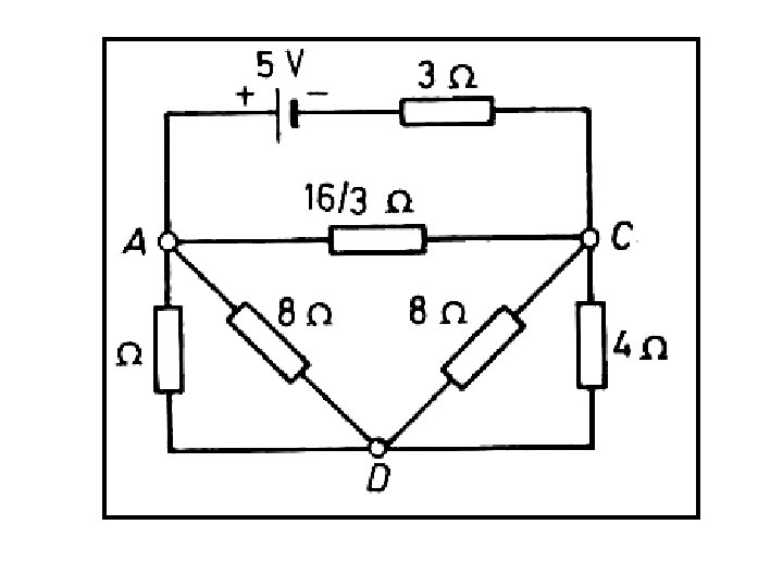
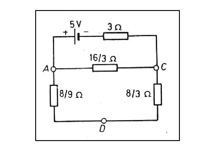
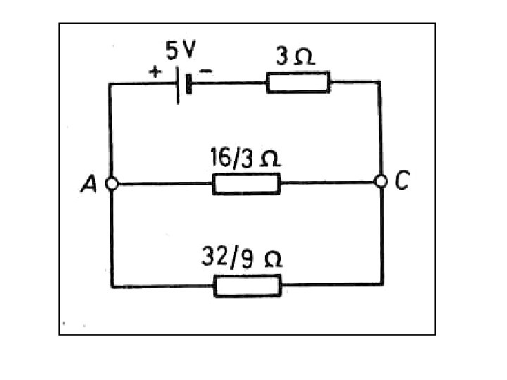

Ans. : 0. 974 A

Note : • During the network reduction or simplification process, some points in the original network are lost. • Care must be taken during this process that no point of ultimate relevance is lost.

Review • • • Star-Delta Transformation. Equivalence. DELTA to STAR to DELTA. Problems. Important Note.

NODAL ANALYSIS Definition of Nodal Analysis Nodal analysis is a method that provides a general procedure for analysing circuits using node voltages as the circuit variables. Nodal Analysis is also called the Node –Voltage Method. In analysing a circuit using Kirchhoff's circuit laws, one can either do nodal analysis using Kirchhoff's current law (KCL) or mesh analysis using Kirchhoff's voltage law (KVL) Nodal analysis writes an equation at each Electrical node, requiring that the branch currents incident at a node must sum to zero.

Types of Nodes in Nodal Analysis • Non Reference Node It is a node which has a definite Node Voltage. e. g. Here Node 1 and Node 2 are the Non Reference nodes • Reference Node - It is a node which acts a reference point to all the other node. It is also called the Datum Node.
 Mark all nodes. Normally there")
Steps Taken While Solving Problem By Nodal Analysis: 1) Mark all nodes. Normally there is a return path which is datum node D. All voltages are to be determined w. r. t. node D. 2) Certain nodes are super nodes whose potential are already known. 3) At each node, find the currents through various branches and equate the algebraic sum to 0 4) If a branch consists only one resistance, then normally current is assumed to flow away from node, such as VA/R 4 or VB/R 5. 5) For a common branch between two nodes, one of the node voltage is assumed to be of higher value and other of lower value. then difference of voltages will make the current to flow from higher node voltage to lower node voltage. For example current through branch AB is (VA - VB)/R 2. But the same current can be written as (VB - VA)/R 1. Flowing from B to A. 6) Write down all such equation on node basis. For node A it is , (VA – E 1)/R 1 + (VA/R 4) + (VA –VB)/R 2 = 0 For node B it is , (VB –VA )/R 2 + (VB/R 5) + (VB + E 2 )/R 3 = 0 7) Solve these equations & also current in different branches can also calculated.
 Calculate the value of branch for network shown in fig. Examples of nodal")
1) Calculate the value of branch for network shown in fig. Examples of nodal analysis
 Calculate the node voltage VB using the nodal analysis")
2) Calculate the node voltage VB using the nodal analysis
Using nodal voltage method find current in the 3 resistance")
3)Using nodal voltage method find current in the 3 resistance
 is a method that is")
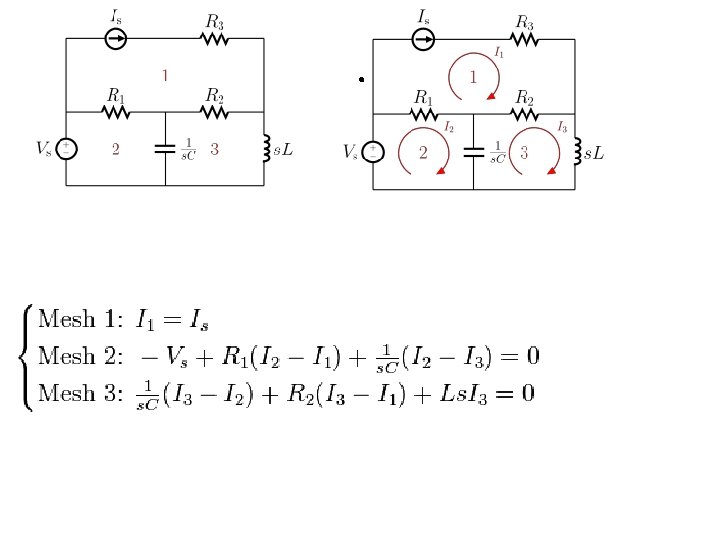
Mesh Analysis Mesh analysis (or the mesh current method) is a method that is used to solve planar circuits for the currents (and indirectly the voltages) at any place in the circuit. Planar circuits are circuits that can be drawn on a plane surface with no wires crossing each other. A more general technique, called loop analysis (with the corresponding network variables called loop currents) can be applied to any circuit, planar or not. Mesh analysis and loop analysis both make use of Kirchhoff’s voltage law to arrive at a set of equations guaranteed to be solvable if the circuit has a solution.

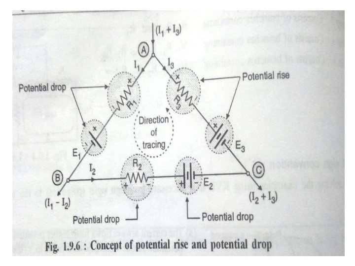
Potential rise and potential drop for a Resistor: Potential rise : If we trace the path along a closed loop from negatively marked terminal of a resistor, then the associated potential change is called as the potential rise. Potential drop : If we trace the path along the closed loop from the positive marked terminal to negative marked terminal, then the associated potential change is called as the potential drop.
 Determine the current and power consumed in the 3 resistance of the circuit")
1) Determine the current and power consumed in the 3 resistance of the circuit shown in fig
 Using Kirchhoff's law calculate the current delivered by the battery")
2) Using Kirchhoff's law calculate the current delivered by the battery
 In fig (a) determine V 2 which results in zero current in the")
3) In fig (a) determine V 2 which results in zero current in the branch containing v 1 , using mesh analysis.

- Slides: 85