UNITII DIGITAL SWITCHING What is it all about

UNIT-II DIGITAL SWITCHING

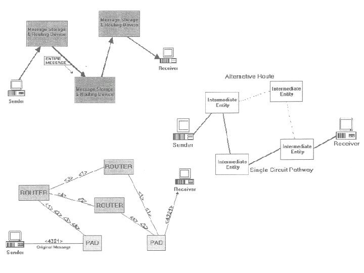
What is it all about? • How do we move traffic from one part of the network to another? • Connect end-systems to switches, and switches to each other • Data arriving to an input port of a switch have to be moved to one or more of the output ports

Types of switching elements • Telephone switches – switch samples • Datagram routers – switch datagrams • ATM switches – switch ATM cells

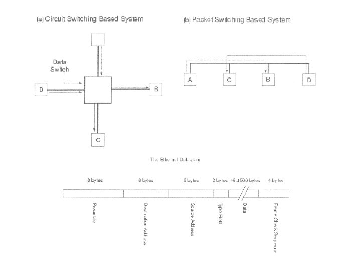
Classification • Packet vs. circuit switches – packets have headers and samples don’t • Connectionless vs. connection oriented – connection oriented switches need a call setup – setup is handled in control plane by switch controller – connectionless switches deal with self-contained datagrams

Crossbar • Simplest possible space-division switch • Crosspoints can be turned on or off • For multiplexed inputs, need a switching schedule (why? ) • Internally nonblocking – but need N 2 crosspoints – time taken to set each crosspoint grows quadratically – vulnerable to single faults (why? )

Multistage crossbar • In a crossbar during each switching time only one crosspoint per row or column is active • Can save crosspoints if a crosspoint can attach to more than one input line (why? ) • This is done in a multistage crossbar • Need to rearrange connections every switching time

Multistage crossbar • Can suffer internal blocking – unless sufficient number of second-level stages • Number of crosspoints < N 2 • Finding a path from input to output requires a depth-first-search • Scales better than crossbar, but still not too well – 120, 000 call switch needs ~250 million crosspoints

Time-space switching • Precede each input trunk in a crossbar with a TSI • Delay samples so that they arrive at the right time for the space division switch’s schedule

Dealing with blocking • Overprovisioning – internal links much faster than inputs • Buffers – at input or output • Backpressure – if switch fabric doesn’t have buffers, prevent packet from entering until path is available • Parallel switch fabrics – increases effective switching capacity

Three generations of packet switches • Different trade-offs between cost and performance • Represent evolution in switching capacity, rather than in technology – With same technology, a later generation switch achieves greater capacity, but at greater cost • All three generations are represented in current products

First generation switch • Most Ethernet switches and cheap packet routers • Bottleneck can be CPU, host-adaptor or I/O bus, depending

Example • First generation router built with 133 MHz Pentium – Mean packet size 500 bytes – Interrupt takes 10 microseconds, word access take 50 ns – Per-packet processing time takes 200 instructions = 1. 504 µs • Copy loop register <- memory[read_ptr] memory [write_ptr] <- register read_ptr <- read_ptr + 4 write_ptr <- write_ptr + 4 counter <- counter -1 if (counter not 0) branch to top of loop • 4 instructions + 2 memory accesses = 130. 08 ns • Copying packet takes 500/4 *130. 08 = 16. 26 µs; interrupt 10 µs • Total time = 27. 764 µs => speed is 144. 1 Mbps • Amortized interrupt cost balanced by routing protocol cost

Second generation switch • Port mapping intelligence in line cards • ATM switch guarantees hit in lookup cache • Ipsilon IP switching – assume underlying ATM network – by default, assemble packets – if detect a flow, ask upstream to send on a particular VCI, and install entry in port mapper => implicit signaling
")
Third generation switches • Bottleneck in second generation switch is the bus (or ring) • Third generation switch provides parallel paths (fabric)
 • Features – self-routing fabric – output buffer is a")
Third generation (contd. ) • Features – self-routing fabric – output buffer is a point of contention • unless we arbitrate access to fabric – potential for unlimited scaling, as long as we can resolve contention for output buffer
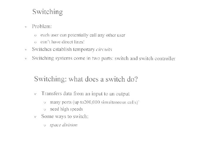

The importance of switching in communication • The cost of switching is high Definition: • Transfer input sample points to the correct output ports at the correct time Terminology • Switching • Digital switching (sample points amplitudes are 0's and 1's) • PABX • Circuit switching • Packet switching

Space division

Voice digitization: • W=3 KHz, sampling at 2*3=6 or 8 KHz • 256 levels for quantization (8 bits) • Bit rate=64 Kb/s Telephone switching • Time division multiplexing: time slot (0. 1 ms), field, frame; • 125 ms/0. 8=150 channels + time for synchronization and control

Switch architecture • Sampling input signals, storing values in memory, placing values in the proper field and frame of the output sequence • Need for more channels: hierarchical switching • Combining time and space switching

Switching techniques and networking • Switching is the technology allowing to get a message between the nodes of a network • Crossbar switching: mechanical (in the past) or electronic. • Bus and cable switches: computer buses or cables (switching + transportation = network) • Token passing approach (similar to the locks used by multiprocessors connected by a bus) • Ethernet approach: cable or ring, packets, conflicts, resending • Synchronization and Hub switch: star networks (no conflicts)
 Linear, (b) Spine, (c) Tree, (d) Segmented.")
Ethernet Cabling Cable topologies. (a) Linear, (b) Spine, (c) Tree, (d) Segmented.

Time division switching • Key idea: when demultiplexing, position in frame determines output link • Time division switching interchanges sample position within a frame: – Time slot interchange (TSI) M U X TSI D E M U X #26
 : example sessions: (1, 3) (2, 1) (3, 4) (4,")
Time Slot Interchange (TSI) : example sessions: (1, 3) (2, 1) (3, 4) (4, 2) 1 2 3 4 4 3 2 1 1 2 3 4 2 3 1 4 2 4 1 3 Read and write to shared memory in different order #27
 Limit is the time")
TSI • • Simple to build. Multicast: easy (why? ) Limit is the time taken to read and write to memory For 120, 000 telephone circuits – Each circuit reads and writes memory once every 125 ms. – Number of operations per second : 120, 000 x 8000 x 2 – each operation takes around 0. 5 ns => impossible with current technology • Need to look to other techniques #28

Time-Space: Example time 1 time 2 2 1 4 3 TSI 3 4 3 1 2 4 TSI Internal speed = double link speed #29

From space switch to T-S-T switch n. . . . 2 1 k. . 2 1 TSI N/n k. . 2 1 TSI 2 n. . . . 2 1 TSI 1 2 1 k. . . . 2 1 2 1 TSI 2 TSI N/n n. . . . 2 1 Replace each first-stage and every last-stage switch by a TSI. Replace multiple intermediate-stage switch with a single time-shared space switch. • The intermediate stage switch is a single switch of size: The intermediate stage switch is reprogrammed for each of the k time slots. last updated March 8, 04 M. Veeraraghavan 30

Internal Non-Blocking Types • Re-arrangeable – Can route any permutation from inputs to outputs. • Strict sense non-blocking – Given any current connections through the switch. – Any unused input can be routed to any unused output. • Wide sense non-blocking. – – There exists a specific routing algorithm, s. t. , for any sequence of connections and releases, Any unused input can be routed to any unused output, assuming all the sequence was served by the routing algorithm. #32

Circuit switching - Space division • graph representation – transmitter nodes – receiver nodes – internal nodes • Feasible schedule – edge disjoint paths. • cost function – number of crosspoints (complexity of Ax. B is AB) – internal nodes #33

Crossbar - example 1 2 3 4 #34

outputs inputs Another Example #35
 (2, 6) (3, 1) (4, 4) (5,")
Another Example outputs inputs sessions: (1, 3) (2, 6) (3, 1) (4, 4) (5, 2) (6, 5) #36
 : N - inputs/outputs; cross-points: 2 (N/n)nk +")
Clos Network Clos(N, n , k) : N - inputs/outputs; cross-points: 2 (N/n)nk + k(N/n)2 nxk 2 x 2 N 2 x 2 (N/n)x(N/n) 3 x 3 2 x 2 N/n kxn 2 x 2 N=6 n=2 k=2 2 x 2 k N/n #37

Clos Network - strict sense nonblocking • Holds for k 2 n-1 • Proof Methodology: – – – Recall: IF [A, B S and |A|+|B| > |S|] then A∩ B≠Ø S= The k middle switches A = middle switches reachable from the inputs B = middle switches reachable from the outputs Our case: • |S|=k • |A| ≥ k-(n-1) • |B| ≥ k-(n-1) #38

No. 4 ESS TOLL SWITCH Basic Concepts • We will define basic telecommunication terms, such as: – analog – digital – bandwidth – compression – protocols – codes and bits

The architecture or protocol suite is the umbrella under which the devices communicate with each other

Congestion • All networks are limited in how many peripherals they can support without experiencing too much degradation • Today more and more peripherals are being added to networks • New ways to eliminate congestion on a network have been developed

Eliminating Congestion • Multiplex: – to transmit two or more signals over a single channel • Compression: – reducing the representation of the information, but not the information itself – reducing the bandwidth or number of bits needed to encode information or a signal

Multiplexing • Several devices can share a telephone line • T-1 telephone line will carry 24 communication paths on one high-speed link • T-3 provides 672 communication paths on one link

Compression • Applications such as: graphics, x-ray images, video are bit intensive • Thus require high bandwidth when transmitting • Compression reduces the number of bits needed to transfer

Analog and Digital • Telephone system developed to transmit speech • Spoken words are transmitted as analog sound waves • People speak in an analog format, in waves • Telephone system was completely analog until 1960

Analog Signals • Move down telephone lines as electromagnetic waves • The way it travels is expressed in frequency • Frequency refers to the number of times per second that a wave oscillates or swings back and forth in a complete cycle from its starting point to its ending point

Analog Signals • A complete cycle occurs when a wave starts at a zero point of voltage, goes to the highest positive point of the wave, down to the negative voltage portion, and then back to zero voltage

Analog Signals • The higher the speed or frequency, the more complete cycles of a wave are completed in a period of time • This speed or frequency is measured in Hertz • Hertz: a measurement of frequency in cycles per second, 1 hertz is 1 cycle p/sec

Hertz • A wave that oscillates or swings back and forth 10 times per second has a speed of 10 hertz or cycles per second • Bandwidth or range of frequencies a service occupies is determined by subtracting the lower range from the higher range • 300 -3300 Hz (voice)= 3300 -300= 3000 Hz
 Microwave Radio (2 -12 GHz) Analog")
Analog Services • • Voice (300 -3300 Hz) Microwave Radio (2 -12 GHz) Analog cable TV signals (54 -750 MHz) Oscillate between a specific range of of frequencies

Analog versus Digital • Analog system can no longer handle the increase in the number of calls that are being generated, was designed for lower volume • Digital networks are faster, have more capacity, and are more reliable

Impairments on Analog Services • Analog signals loose their power the longer they travel • Signal meets resistance in the media (copper, coaxial cable, air), causes fading of the signal or attenuation of the signal • Analog signals also pick up noise or electrical energy while travelling from power lines, light sources, and electrical machinery • Requires: amplification to inhibit attenuation

Amplification • To overcome resistance in a signal, analog signals are amplified while they travel over a medium • Drawbacks amplification: – also increases level of noise in signal

Digital Signals • Advantages digital signals: – higher speeds – clearer voice quality – fewer errors – less complex peripheral equipment required

Digital Signals • No waves are transmitted • Digital signals are transmitted in the form of binary bits • Binary = being composed of two parts • In telecommunications this means only on or off, one or zero piece(s) of information transmitted

Applications • Wideband: – TV – Cable – Connections between telephone offices • Narrowband: – phone connection to end users

Protocols • Enable computers to communicate with each other • Spell out the rules of interaction between two or more computers • Handle error detection and correction and file transmission

Examples of Protocols • Who transmits first? • What is the structure of the addresses of devices such as computers? • How are errors fixed? • How long to wait before disconnecting? • How to package data to be sent?

Architecture • Ties computers and peripherals together into a coherent whole • Forms the network which connects all devices together • Layers within architectures have protocols to define functions such as routing, error checking and addressing

OSI • Not widely implemented • Laid foundation for the concept of open communications among vendors • Basic concept of layering of groups of functions into 7 layers • Each layer can be changed and developed independently

Bridges • Used to connect a small number of LAN’s • Provide one common path to connect several LAN’s • Easy to configure, all data sent to all devices on a network, appropriate device picks it up, broadcast feature • Lack routing and congestion control
 •")
Routers • Used to connect multiple LAN’s over large distances (differing buildings, cities) • More sophisticated than bridges • Can handle differing protocols from various LAN’s

Switching Routers • Faster than non-switching routers • Do not look up in tables where to send data • Address placed in the pack sent
- Slides: 62