Unit1 FUNDAMENTALS OF ROTATING MACHINES Introduction Rotating machines


- Slides: 36
Unit-1 FUNDAMENTALS OF ROTATING MACHINES
Introduction • Rotating machines are usually called turbo machines. • These machines work on the principle of work addition or extraction. • When a fluid passes through a rotating machine two things happen, viz. energy transfer and energy transformation. • The energy transfer means transfer of available energy from one part (rotor) to the medium (fluid) or vice versa.
• Energy transformation means change of one form of energy into another form, for example, change of kinetic energy to pressure energy in a compressor. • The energy transfer can occur only in its moving or rotating elements whereas the energy transformation can occur in both stationary and rotating elements.
General Fluid Dynamics Analysis Figure 1 shows the details of the passage of a fluid through a rotor of any shape. The rotor has an axis A − A and rotates at a steady angular velocity of ω radians per second.
From figure , • Let us assume that at point 1 the fluid enters with a velocity c 1 and leaves at point 2 with velocity c 2. • The radial distance of these points from the axis A-A is r 1 and r 2 respectively. • The velocity c 1 can be represented by three velocity components,
• ca 1 : axial velocity in a direction parallel to the axis A - A • cr 1 : radial velocity in the direction normal to A -A • ct 1 : tangential velocity in the direction normal to any radius • Similarly, at the exit point 2, the velocity c 2 will have three components, ca 2; cr 2 and ct 2 respectively.
Fig 2 shows the Energy transfer in a turbo machine.
W. k. t. • The angular speed of the rotor is ω radians per second. ω= 2πN/60 • The peripheral velocities of the blades at the entry and exit corresponding to diameters d 1 and d 2 are u 1 = πNd 1/60 u 2= πNd 2/60
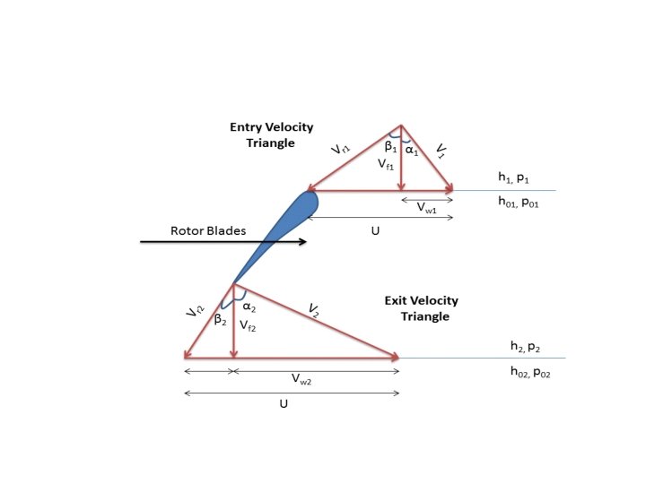
Velocity triangle • In turbo machinery, a velocity triangle or a velocity diagram is a triangle representing the various components of velocities of the working fluid in a turbo machine. Velocity triangles may be drawn for both the inlet and outlet sections of any turbo machine.
General Thermodynamic Analysis of fluid flow
Cycle arrangements • Open-cycle arrangements • Closed-cycle arrangements
Open- cycle arrangements • Fresh atmospheric air is drawn into the circuit continuously • Energy is added by the combustion of fuel in the working fluid • Products of combustion expanded through turbine and exhausted into the atmosphere
Gas turbine with single-shaft arrangement
Single Shaft Arrangement with a Heat exchanger
Why Heat-exchanger? ? ? • Improves ηthermal, for a given size of the plant. • Power output reduces by 10% due to pressure losses in HE • Reduces the fuel
Single Shaft Arrangement – Alternative Arrangement
• The above arrangement more suitable for fuels whose products of combustion contain constituents which may corrode or erode the turbine blades. • It is much less efficient than the simple cycle power plant. • Only inferior or pulverized coal are to be used.
Twin Shaft Arrangement
• The compressor and high pressure turbine combination acts as a gas generator for the low pressure turbine. • Fuel flow to the combustion chamber is controlled to achieve variation of power. • This will cause decrease in pressure ratio and maximum temperature. • At off- design conditions the power output reduces, with the result that thermal efficiency deteriorates considerably at part loads.
Series Flow Twin Shaft Arrangement
Parallel Flow Twin Shaft Arrangement
• Series and Parallel flow arrangements power output is controlled by the adjustment of fuel supply to the combustion chamber in the power turbine line. Performance can be improved • 1. Reducing the work of compression. • 2. Increasing the work of expansion.
Series flow with intercooling
Series flow with reheating
Straight compound twin-spool arrangement
• The LP compressor is driven by the LP turbine and the HP compressor by the HP turbine. • This arrangement is called straight compounding. • This arrangement is widely used shaft power units and for the turbojet engines, employing pressure ratios in the range of 10: 1 to 20: 1.
Closed Cycle arrangement
Closed Cycle arrangement with air as working medium
Closed cycle arrangement with working medium other than air
The Closed cylce basic requirements of the working medium In a closed- cycle arrangement, the operating medium can be other than air and it must satisfy the following requirements. • Availability as well as cheapness of the working medium. • The circulating working medium must be stable, non -explosive and non-corrosive. • It must be non-toxic and non-flammable. • It should have high specific heat value Cp and high specific heat ratio, γ • It must have a higher thermal conductivity, k
Properties of various working media The work done during compression per kg of flow of any gas is given by Wc=Cp(T 2 -T 1) and the temperatures after compression, T 2, is given by T 2=T 1 r γ-1/ γ where r is the pressure ratio
Applications • Gas turbines can be classified into aircraft and industrial gas turbines. • The aircraft gas turbines differ from the industrial gas turbines in three main aspects. 1. The life of the industrial gas turbine is expected to be of the order of 120, 000 hours without major overhaul as against 600 -1200 hours for aircraft gas turbines.
2. Size and the weight of an aircraft power plant is very crucial compared to industrial units. 3. The aircraft power plant can make use of kinetic energy of the gases leaving the exhaust whereas it is wasted in other types and consequently, this energy loss must be kept as minimum as possible.
Apart from aircraft market, the gas turbines are used in • naval operations , • rail transport, • automobile industries
End