Synchronous Digital Design Methodology and Guidelines Digital System


")

")
- Slides: 30
Synchronous Digital Design Methodology and Guidelines Digital System Design
Synchronous Design • All flip-flops clocked by one common clock • Reset only used for initialization • Races and hazards are no problem
Synchronous Design • Three things must be ensured by the designer: – Minimize and determine clock skew – Account for flip-flop setup and hold times – Reliably synchronize asynchronous inputs
Timing Analysis
Clock skew
Example • Determine the maximum frequency of the following circuit with and without skew
Clock Jitter
Clock Gating • Clock gating is done to disable the clock for low power consumption using a clken signal • It is wrong to gate the clock in the following way, instead use a synchronous load (enable) signal
Asynchronous Inputs It is impossible to guarantee setup and hold timing constraints on inputs synchronized with a clock unrelated to the system clock
Asynchronous inputs • Synchronize only in one place
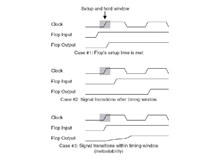
Metastability • Metastability is a phenomenon that may occur if the setup and hold time requirements of the FF are not met, leading in the output settling in an unknown value after unspecified time.
MTBF
Reliable synchronizer design
Multi-cycle synchronizer
Example • Design a synchronizer that synchronizes two inputs async 1 and async 2 generated with a 50 MHz clock CLK 1, to a system with a 33 MHz clock CLK 2 totally independent of CLK 1. Draw appropriate timing diagrams.
Multi-cycle synchronizer with deskewing
Cascaded synchronizer
Example • Design a digital synchronizer to capture valid data according to the following timing diagram
Solution
Synchronizing high-speed data transfers • What happens when the asynchronous inputs are clocked faster than the system clock?
Case study: Ethernet receiver
Byte holding register
SCTRL circuit
Testing Basics Defect: A difference between intended design and actual hardware Error: A wrong output produced through a defect Fault: A defect in a higher abstraction level
Example
Controllability and observability • Controllability: The difficulty of setting a specific signal to 0 or 1 • Observability: The difficulty of reading a specific signal • Electron beam testing is too expensive • Must set signal through primary inputs and observe through primary outputs
Design For Testability (DFT)
Boundary scan • In boundary scan, all flip-flops enter a test mode where they are controllable and observable • After functional verification, normal flipflops are replaced by scan flip-flops • Only D flip-flops must be used • Clocks must not be generated internally
Built-In Self-Test (BIST)