Super Visor Eng Emad Alqasem Outline Project description


 = 25")
 � 2009 International Building Code")


")


")


 the column is short")
: �ɸPn = ɸλ {0. 85 fˋc(Ag-Ast) + Fy.")


 check punching shear has been used Part A")
(28)1/2(6800)(1000)/1000=8995 k. N>Pu �Part C")
 of part A")
 of part A")


 part (A)")
 part (A)")
 part (A)")

- Slides: 65
Super Visor: Eng. Emad Al-qasem
Outline � Project description � Philosophy of analysis & design � Design Of Slab � Design Of Beam � 3 -D Model � Design of column � Design of footing � Dynamic analysis
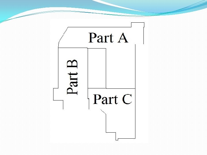
Project description �Faculty of science building in king Khalid university located in Saudi Arabia. �Area of the part that we take to design = 7250 m 2
Philosophy of analysis & design �Ultimate design method is used to analysis and design of one way solid slab �the slab are carried over drop beams �Columns carrying an axial loads calculated by tributary area
materials of construction �Reinforced concrete �The unit weight of concrete ( ) = 25 k. N/m 3. �The required compressive strength after 28 days is fc = 28 MPa. �The yield steel bars required Fy = 420 MPa.
Code used �American concrete institute code (ACI 318 -08) � 2009 International Building Code (IBC )
Loads Dead load: � Own weight for slab = 6. 25 k. N/m 2. � Super imposed load = 3. 44 k. N/m 2. Live load: �for Garage = 3 KN m 2. �for all the class room = 2. 4 KN m 2. �for corridors = 4. 8 KN m 2.
Load Combination �Ultimate load = 1. 2 D+1. 6 L Where: D: dead load L: live load
Design Of Slab
Slab �One way solid slab is used in the building �slab thickness is determined according to deflection control according to ACI code �Minimum thickness = Ln/24 = 22 cm thickness used = 25 cm
Check shear for slab �Ln max = 6 - 0. 4 = 5. 6 m �Vu =42. 5 k. N at distance d from face of column. � Vc =0. 75*0. 166*(28)1 2 *1000*220/1000 = 145 k. N 145 > 42. 5 ……… OK
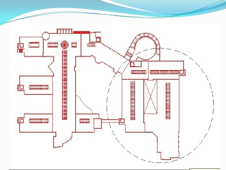
Part A Strip Distribution of sub terrain floor
Part A Strip Distribution of ground , first & second floor
Part B Strip Distribution of sub terrain floor
Part B Strip Distribution of Ground & First floor
Part B Strip Distribution of second floor
Part B Strip Distribution of third floor
Part C Strip Distribution of sub terrain floor
Part C Strip Distribution of Ground , First & second floor
Design of strip 1 of sub terrain floor of part (A)
Design Of Beam
�Beams designed using tributary area method. �All beams are dropped. �T & L Section used.
Part A Beams in sub terrain floor
Part A Beams in ground , first & second floor
Part A Beams in third floor
Part B Beams in sub terrain floor
Part B Beams in ground & first floor
Part B Beams in second floor
Part B Beams in third floor
Part C Beams in sub terrain floor
Part C Beams in ground & first floor
Part C Beams in second floor
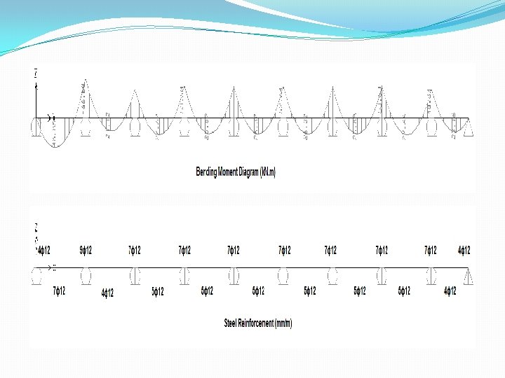
Design beam 1 of ground floor Of part (A)
Av/s =1. 864 S= 80 mm
3 -D Model Part A
Part B
Part C
Required Checks �Compatibility Check �Equilibrium Check �Stress-Strain Relationships
Check compatibility: �This requires that the structure behave as one unit
Equilibrium Check Part C Load Type Hand Calculation From SAP % of Error Live Load 22987. 4 23898 3. 9 Superimposed load 19633 19927 1. 5 Dead Load 73829 77101 4. 4
Design Of Column
Columns are divided into five groups : Each group include columns with ultimate axial load : � group 1 (800 2500) k. N, � group 2 (2500 4000) k. N, � group 3 (4000 5500) k. N, � group 4 (5500 7000) k. N, � and group 5 (7000 8500) k. N.
Check buckling �If KL/r ≤ 34 -12 (M 1/M 2) the column is short � KL/r = 1(4. 5)/0. 3(0. 8) = 18. 75 < 22 �Can be considered as short column
Design of columns in group (1): �ɸPn = ɸλ {0. 85 fˋc(Ag-Ast) + Fy. Ast} � 2500 x 103=0. 65 x 0. 8{0. 85 x 40(Ag-0. 01 Ag)+420 x 0. 01 Ag} �Ag =1270 Cm 2 � Use 40*40 ……… Ag =1600 Cm 2 �Ast=0. 01 x 160000=1600 mm 2 (use 4ɸ 25 mm)
�Spacing between stirrups: �S ≤ At least dimension of the column = 40 cm 16 db =16 x 2. 5=40 cm 45 ds =45 x 1 =45 cm �Ties (1ɸ 10 mm/40 cm)
Design Of Footing
selection of footing �Since the area of all single footings >> 60% the area of building �Then using mat foundation
Mat foundation: �this type of foundation is used when the allowable bearing capacity of soil is very low and very large load on it.
�To calculate the effective depth (d) check punching shear has been used Part A � VC =0. 75(1/3)f`C 1/2 bod �Assume d=1. 25 m � VC =0. 75(1/3)(28)1/2(4600)(1250)/1000=7607 k. N>Pu
�Part B �Assume d=1. 0 m � VC =0. 75(1/3)(28)1/2(6800)(1000)/1000=8995 k. N>Pu �Part C �Assume d=1. 1 m � VC =0. 75(1/3)(28)1/2(4000)(1100)/1000=5820 k. N>Pu
Ultimate bending moment (m 11) of part A
Ultimate bending moment (m 22) of part A
Reinforcement for part A � Take the moment from SAP to compute the reinforcement � min= 0. 0018 (b*h)/(b*d) = 0. 0018 (1000*1400)/(1000*1250) = 0. 002 Mu using ( min = 0. 002) = 1162 k. N. m > Mu from SAP � Using As min in both direction (1ɸ 18/100)
Dynamic Analysis
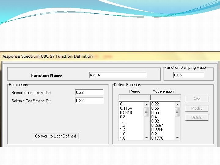
�Dynamic analysis can be used to find dynamic displacements, time history, and modal analysis. �Response spectrum method will be used for seismic analysis as provided in Uniform Building Code for year 97 (UBC 97).
Ca & Cv
Scale factor �Scale factor = g I / Rp = 9. 81 *1. 25 /3 =4
Maximum displacement: From seismic load: (ex) part (A)
Maximum displacement: From seismic load: (e. Y) part (A)
Maximum displacement: From seismic load: (ez) part (A)
Thanks For Listening