Strapdown Inertial Navigation Systems INS Sensors and UAVs
- Slides: 70
Strapdown Inertial Navigation Systems (INS) Sensors and UAVs Avionic By Dr. Hamid Bolandhemmat
CONTENTS • Overview of Inertial Navigation Systems (INS) and their application • General navigation equations in spaced fixed and rotating reference frames • Inertial sensors • Gyroscopes • Underlying theory • Rebalance loop • Random process - review • Sources of errors • calibration • Accelerometers • Underlying theory • Rebalance loop • Sources of errors • Calibration • Compass • Air data systems • Pressure Altitude • Airspeed • Global Positioning Systems (GPS) • Underlying concept
CONTENTS • Global Positioning Systems (GPS) - continue • Clock drift • Trilateration to measure position • A recursive approach for trilateration • Other source of errors – GPS error budget • Velocity measurements – Doppler effect • Differential GPS technology • INS-GPS integration • Complementary aspects of INS and GPS • Multi-sensor inertial navigation systems • Introduction to Estimation and Kalman filtering • Vision systems • Other sensors
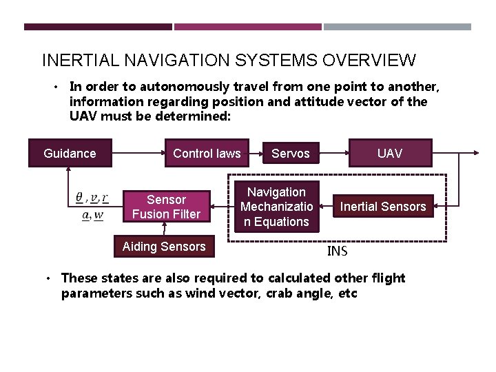
INERTIAL NAVIGATION SYSTEMS OVERVIEW) • In order to autonomously travel from one point to another, information regarding position and attitude vector of the UAV must be determined: Guidance Control laws Sensor Fusion Filter Aiding Sensors Servos Navigation Mechanizatio n Equations UAV Inertial Sensors INS • These states are also required to calculated other flight parameters such as wind vector, crab angle, etc
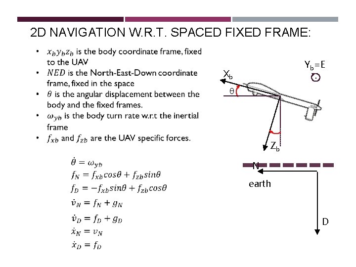
2 D NAVIGATION W. R. T. SPACED FIXED FRAME: Yb=E. Xb q Zb N earth D
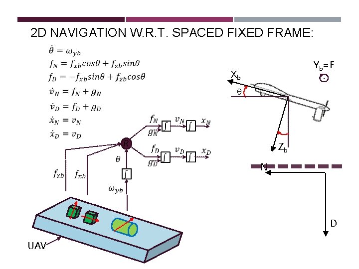
2 D NAVIGATION W. R. T. SPACED FIXED FRAME: Yb=E. Xb q Zb N D UAV
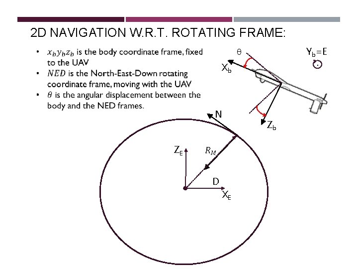
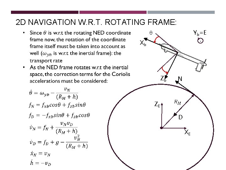
2 D NAVIGATION W. R. T. ROTATING FRAME: Yb=E. q Xb N ZE D XE Zb
2 D NAVIGATION W. R. T. ROTATING FRAME: Yb=E. q Xb Zb N ZE D XE
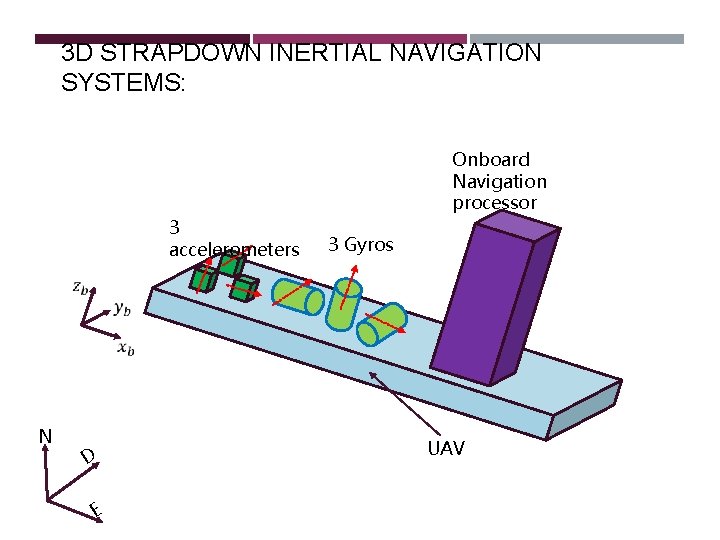
3 D STRAPDOWN INERTIAL NAVIGATION SYSTEMS: Onboard Navigation processor 3 accelerometers N D E 3 Gyros UAV
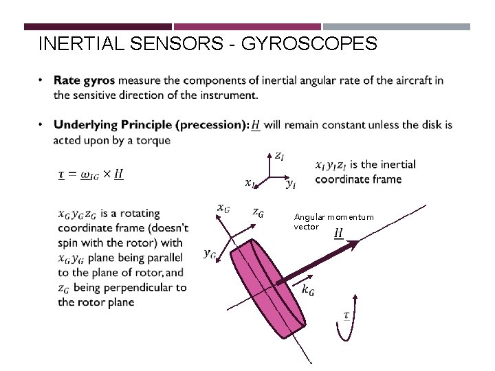
INERTIAL SENSORS - GYROSCOPES Angular momentum vector
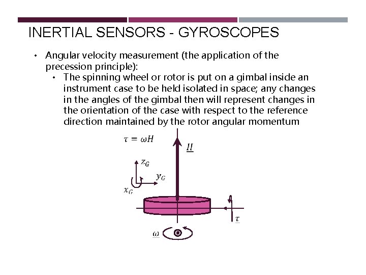
INERTIAL SENSORS - GYROSCOPES • Angular velocity measurement (the application of the precession principle): • The spinning wheel or rotor is put on a gimbal inside an instrument case to be held isolated in space; any changes in the angles of the gimbal then will represent changes in the orientation of the case with respect to the reference direction maintained by the rotor angular momentum
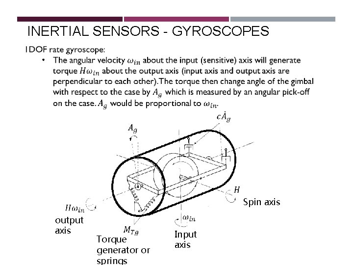
INERTIAL SENSORS - GYROSCOPES Spin axis output axis Torque generator or springs Input axis
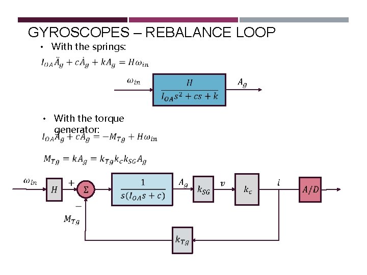
GYROSCOPES – REBALANCE LOOP • With the springs: • With the torque generator:
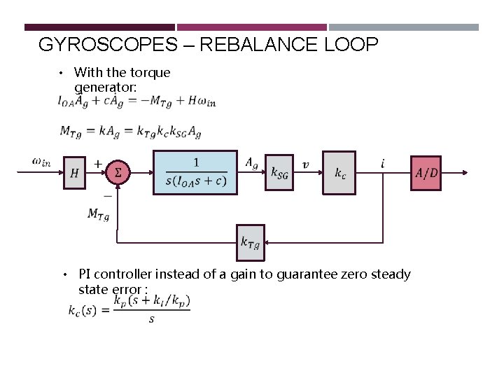
GYROSCOPES – REBALANCE LOOP • With the torque generator: • PI controller instead of a gain to guarantee zero steady state error :
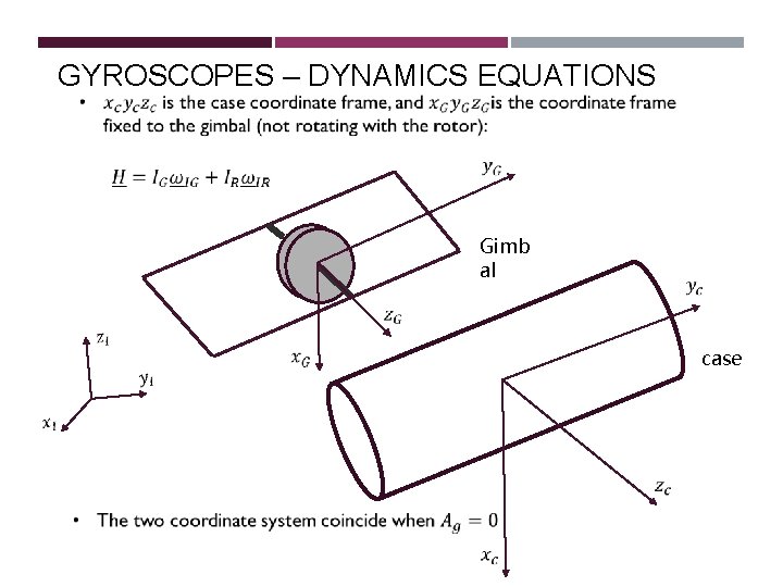
GYROSCOPES – DYNAMICS EQUATIONS Gimb al case
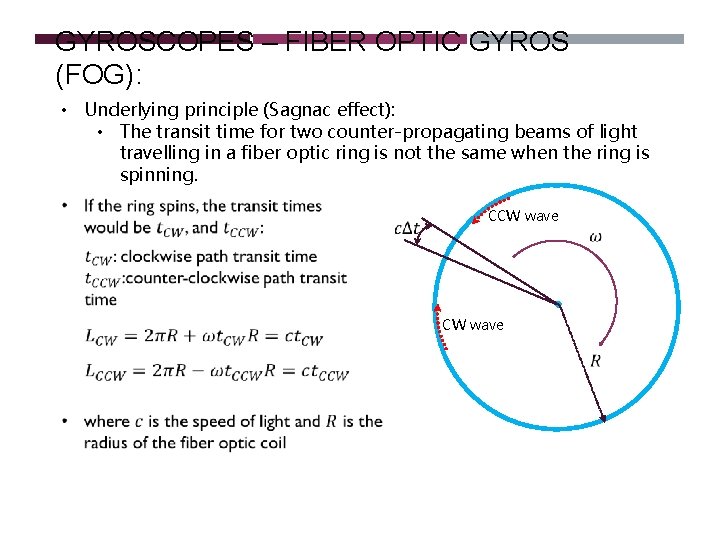
GYROSCOPES – FIBER OPTIC GYROS (FOG): • Underlying principle (Sagnac effect): • The transit time for two counter-propagating beams of light travelling in a fiber optic ring is not the same when the ring is spinning. CCW wave
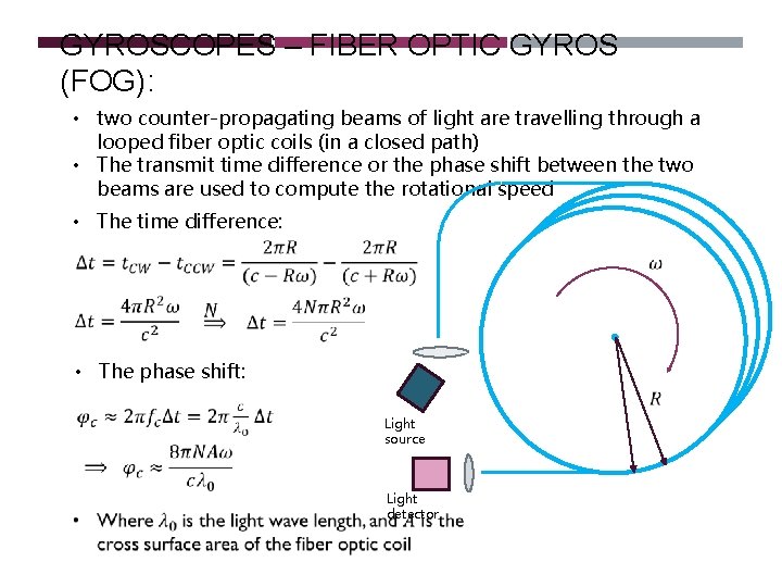
GYROSCOPES – FIBER OPTIC GYROS (FOG): • two counter-propagating beams of light are travelling through a looped fiber optic coils (in a closed path) • The transmit time difference or the phase shift between the two beams are used to compute the rotational speed • The time difference: • The phase shift: Light source Light detector
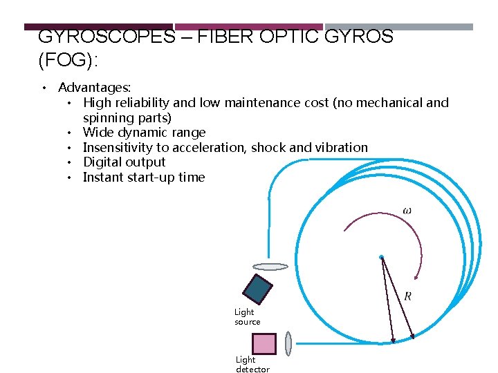
GYROSCOPES – FIBER OPTIC GYROS (FOG): • Advantages: • High reliability and low maintenance cost (no mechanical and spinning parts) • Wide dynamic range • Insensitivity to acceleration, shock and vibration • Digital output • Instant start-up time Light source Light detector
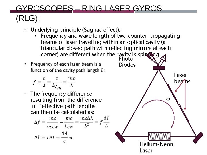
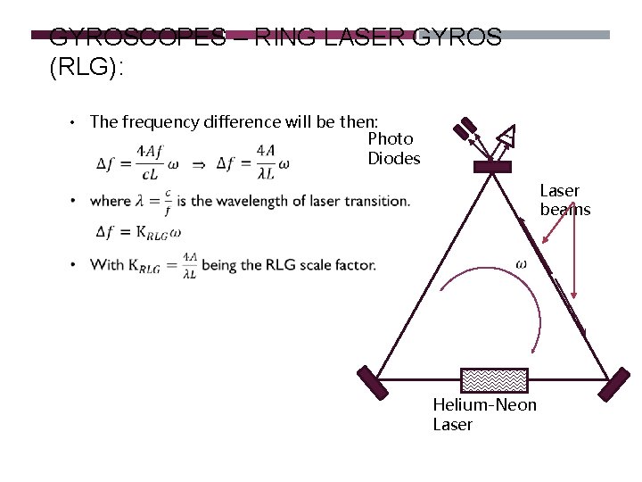
GYROSCOPES – RING LASER GYROS (RLG): • Underlying principle (Sagnac effect): • Frequency and wave length of two counter-propagating beams of laser travelling within an optical cavity (a triangular closed path with reflecting mirrors at each corner) are different when the cavity is spinning. Photo Diodes Laser beams • The frequency difference resulting from the difference in “effective path lengths” can then be calculated as: Helium-Neon Laser
GYROSCOPES – RING LASER GYROS (RLG): • The frequency difference will be then: Photo Diodes Laser beams Helium-Neon Laser
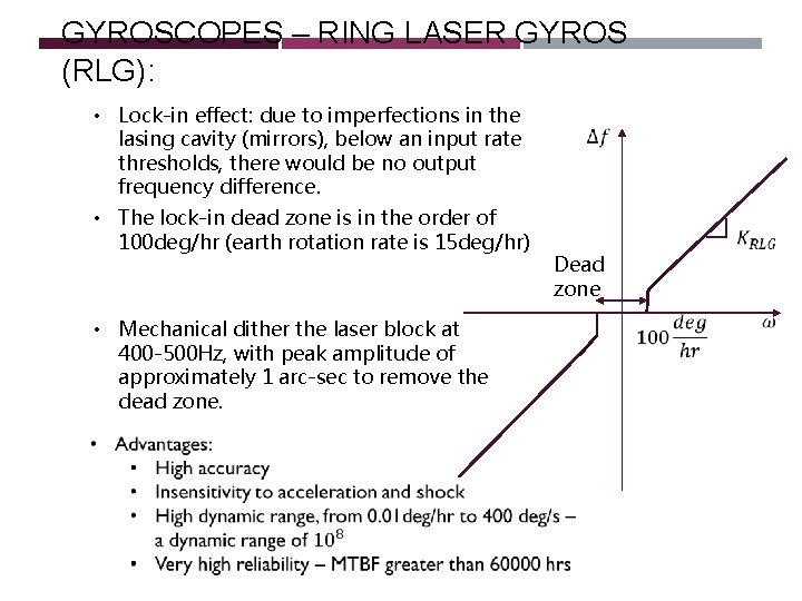
GYROSCOPES – RING LASER GYROS (RLG): • Lock-in effect: due to imperfections in the lasing cavity (mirrors), below an input rate thresholds, there would be no output frequency difference. • The lock-in dead zone is in the order of 100 deg/hr (earth rotation rate is 15 deg/hr) • Mechanical dither the laser block at 400 -500 Hz, with peak amplitude of approximately 1 arc-sec to remove the dead zone. Dead zone
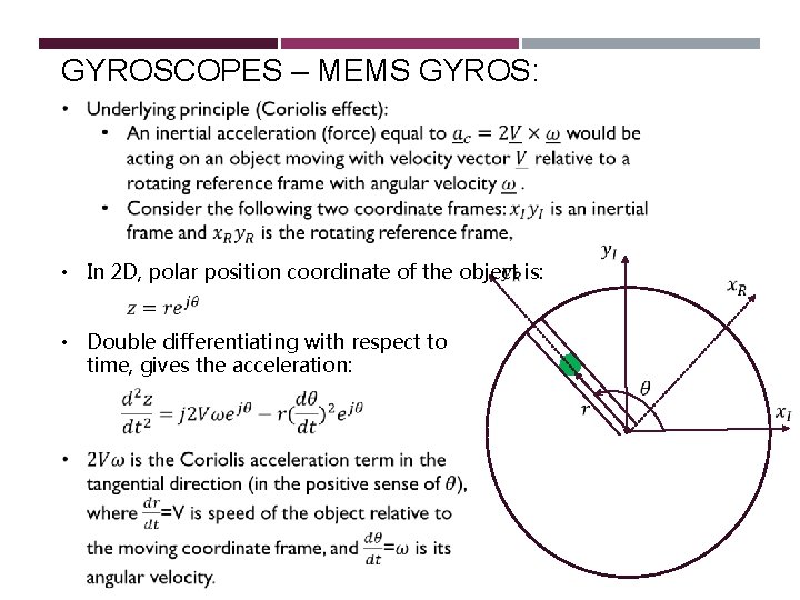
GYROSCOPES – MEMS GYROS: • In 2 D, polar position coordinate of the object is: • Double differentiating with respect to time, gives the acceleration:
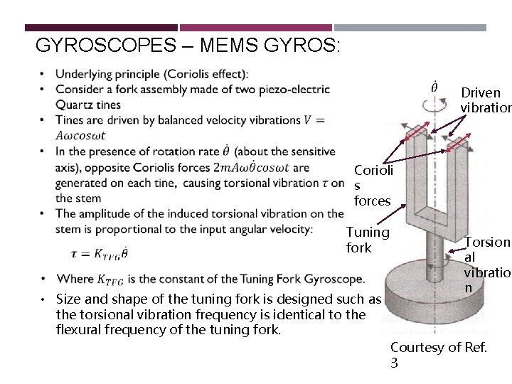
GYROSCOPES – MEMS GYROS: Driven vibration Corioli s forces Tuning fork • Size and shape of the tuning fork is designed such as the torsional vibration frequency is identical to the flexural frequency of the tuning fork. Torsion al vibratio n Courtesy of Ref. 3
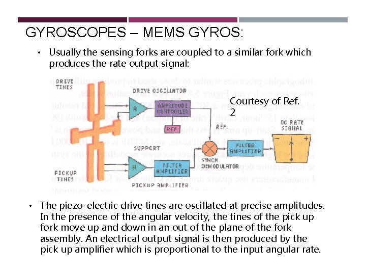
GYROSCOPES – MEMS GYROS: • Usually the sensing forks are coupled to a similar fork which produces the rate output signal: Courtesy of Ref. 2 Corioli s forces • The piezo-electric drive tines are oscillated at precise amplitudes. In the presence of the angular velocity, the tines of the pick up fork move up and down in an out of the plane of the fork assembly. An electrical output signal is then produced by the pick up amplifier which is proportional to the input angular rate.
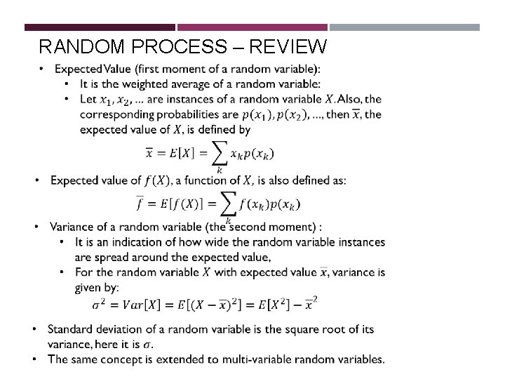
RANDOM PROCESS – REVIEW
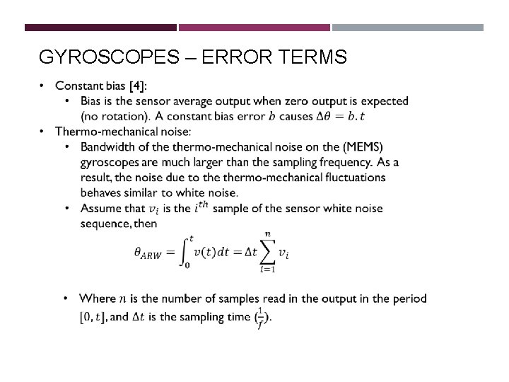
GYROSCOPES – ERROR TERMS
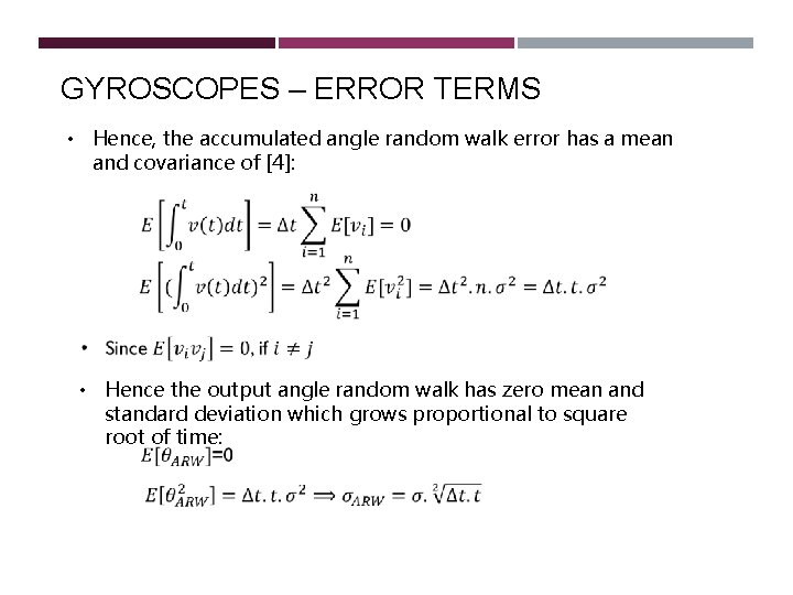
GYROSCOPES – ERROR TERMS • Hence, the accumulated angle random walk error has a mean and covariance of [4]: • Hence the output angle random walk has zero mean and standard deviation which grows proportional to square root of time:
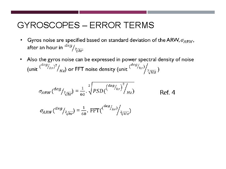
GYROSCOPES – ERROR TERMS Ref. 4
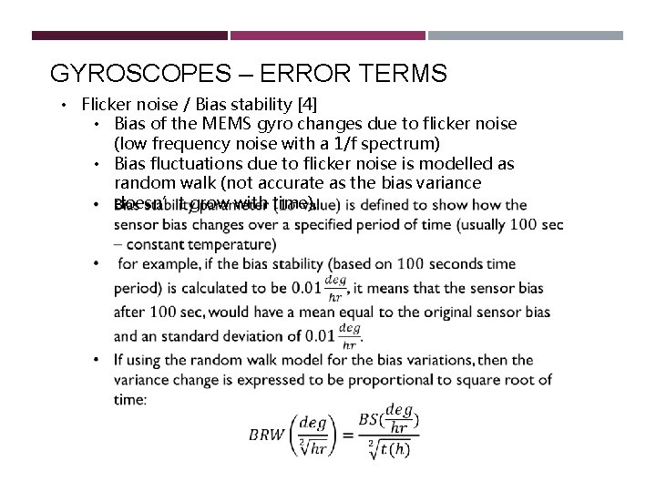
GYROSCOPES – ERROR TERMS • Flicker noise / Bias stability [4] • Bias of the MEMS gyro changes due to flicker noise (low frequency noise with a 1/f spectrum) • Bias fluctuations due to flicker noise is modelled as random walk (not accurate as the bias variance doesn’t grow with time).
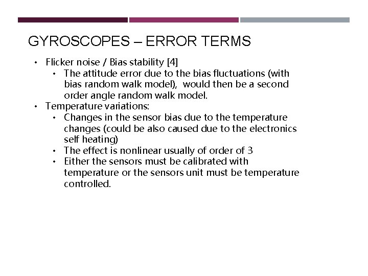
GYROSCOPES – ERROR TERMS • Flicker noise / Bias stability [4] • The attitude error due to the bias fluctuations (with bias random walk model), would then be a second order angle random walk model. • Temperature variations: • Changes in the sensor bias due to the temperature changes (could be also caused due to the electronics self heating) • The effect is nonlinear usually of order of 3 • Either the sensors must be calibrated with temperature or the sensors unit must be temperature controlled.
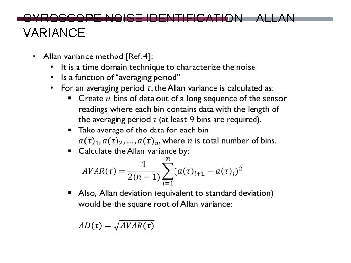
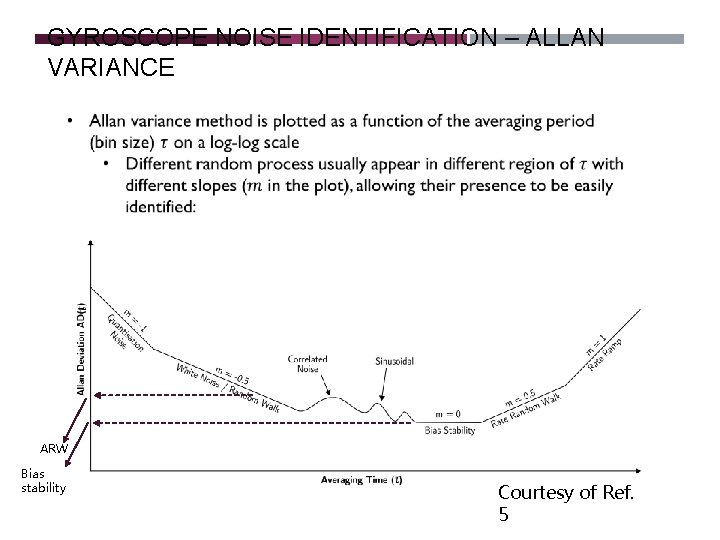
GYROSCOPE NOISE IDENTIFICATION – ALLAN VARIANCE
GYROSCOPE NOISE IDENTIFICATION – ALLAN VARIANCE ARW Bias stability Courtesy of Ref. 5
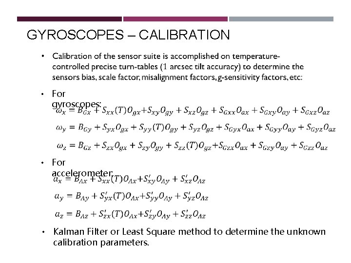
GYROSCOPES – CALIBRATION • For gyroscopes: • For accelerometer: • Kalman Filter or Least Square method to determine the unknown calibration parameters.
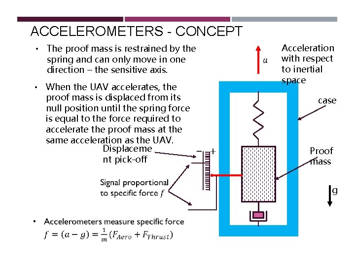
ACCELEROMETERS - CONCEPT • The proof mass is restrained by the spring and can only move in one direction – the sensitive axis. • When the UAV accelerates, the proof mass is displaced from its null position until the spring force is equal to the force required to accelerate the proof mass at the same acceleration as the UAV. Displaceme nt pick-off Acceleration with respect to inertial space case Proof mass g
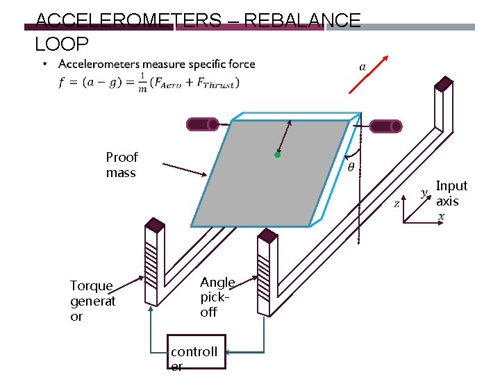
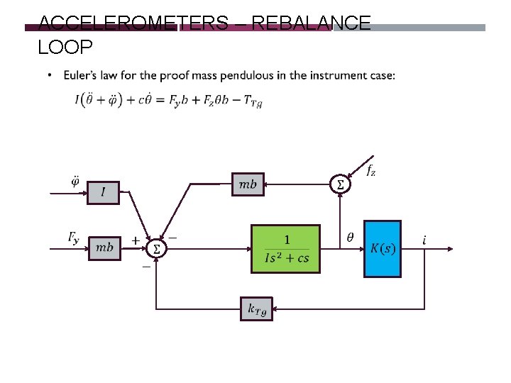
ACCELEROMETERS – REBALANCE LOOP Proof mass Torque generat or Input axis Angle pickoff controll er
ACCELEROMETERS – REBALANCE LOOP
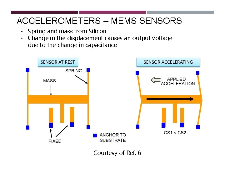
ACCELEROMETERS – MEMS SENSORS • Spring and mass from Silicon • Change in the displacement causes an output voltage due to the change in capacitance Courtesy of Ref. 6
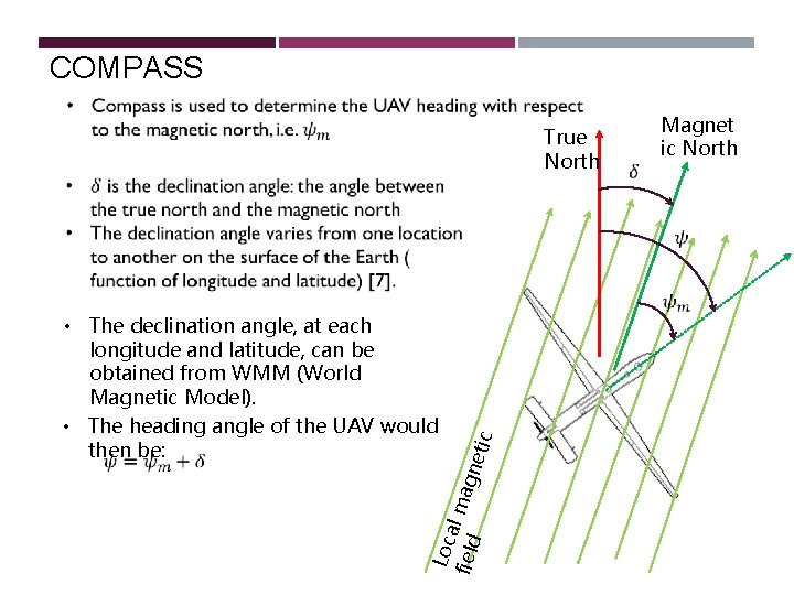
COMPASS Loc a field l magn e • The declination angle, at each longitude and latitude, can be obtained from WMM (World Magnetic Model). • The heading angle of the UAV would then be: tic True North Magnet ic North
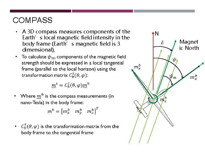
COMPASS • A 3 D compass measures components of the Earth’s local magnetic field intensity in the body frame (Earth’s magnetic field is 3 dimensional), N Magnet ic North
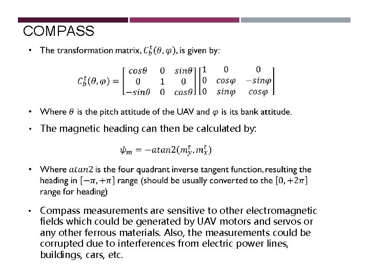
COMPASS • The magnetic heading can then be calculated by: • Compass measurements are sensitive to other electromagnetic fields which could be generated by UAV motors and servos or any other ferrous materials. Also, the measurements could be corrupted due to interferences from electric power lines, buildings, cars, etc.
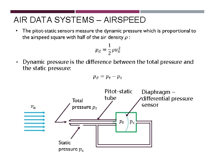
AIR DATA SYSTEMS – AIRSPEED • Dynamic pressure is the difference between the total pressure and the static pressure: Pitot-static tube Diaphragm – differential pressure sensor
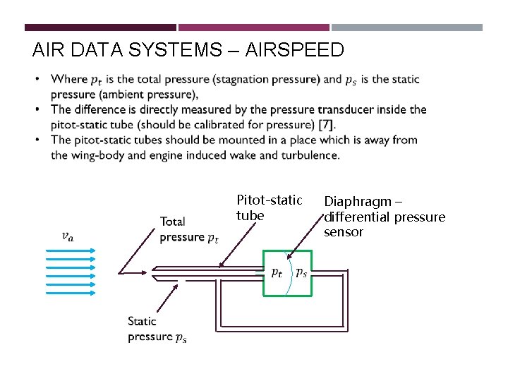
AIR DATA SYSTEMS – AIRSPEED Pitot-static tube Diaphragm – differential pressure sensor
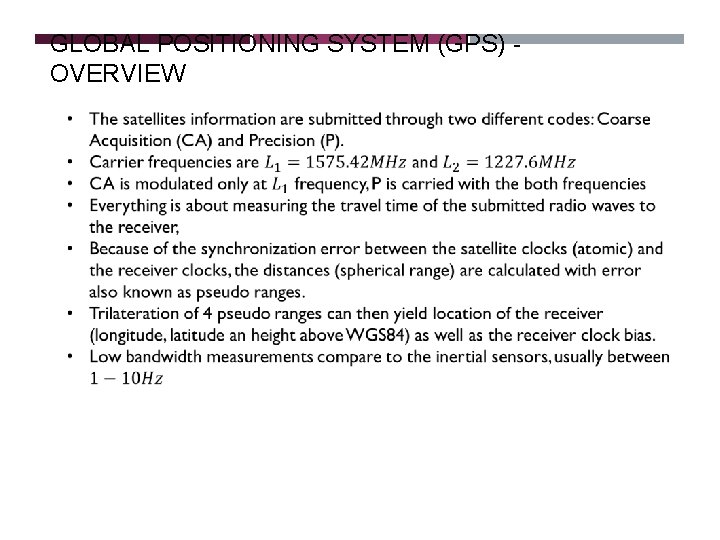
GLOBAL POSITIONING SYSTEM (GPS) OVERVIEW
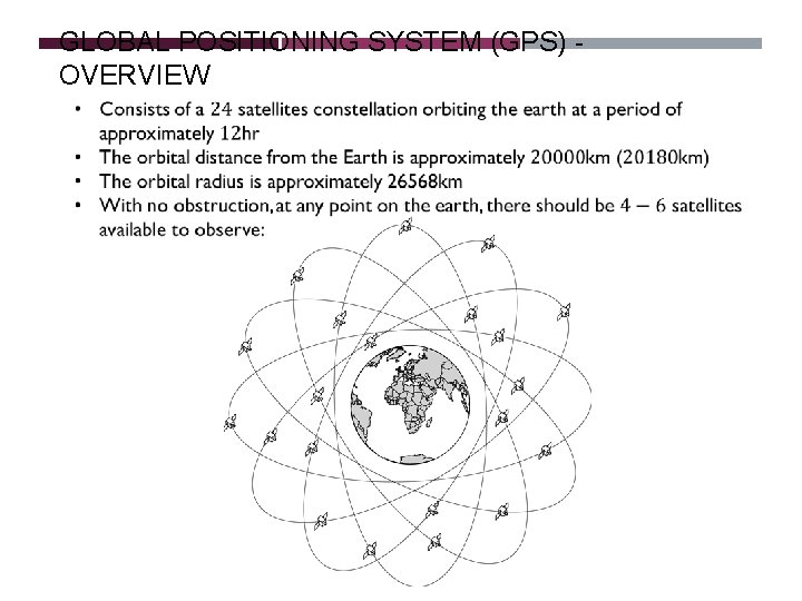
GLOBAL POSITIONING SYSTEM (GPS) OVERVIEW
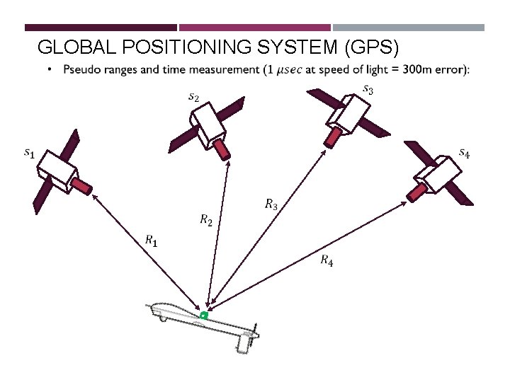
GLOBAL POSITIONING SYSTEM (GPS)
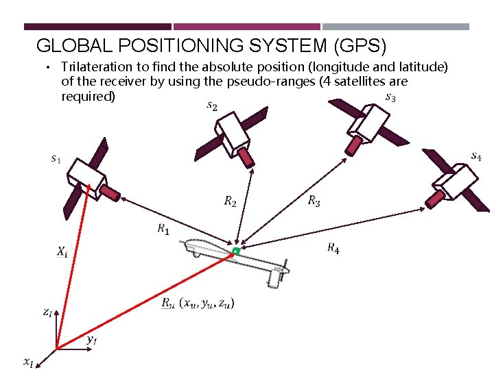
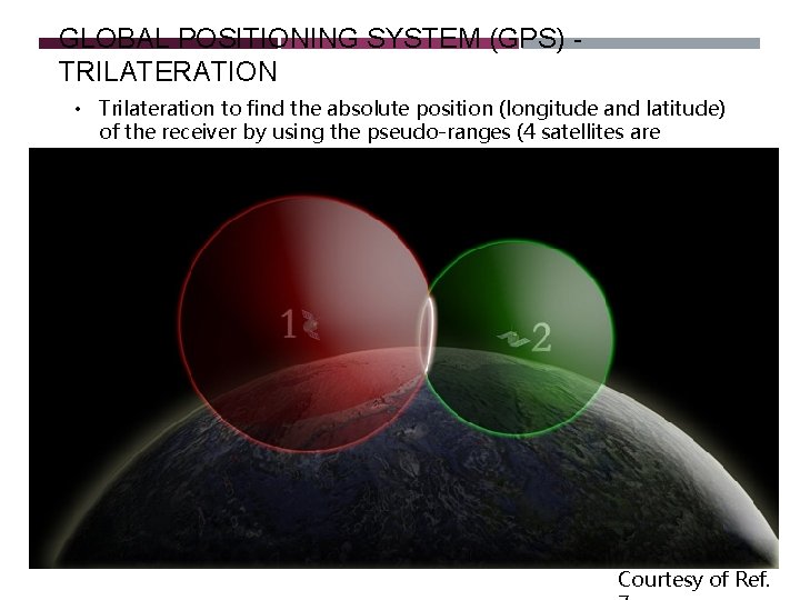
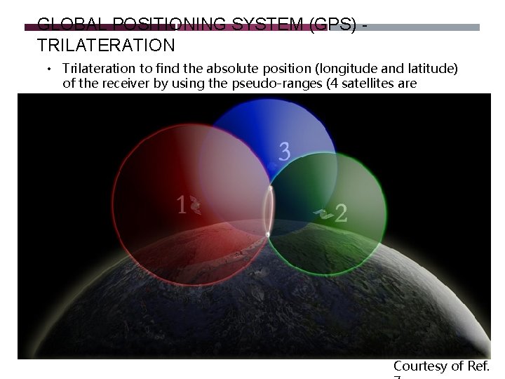
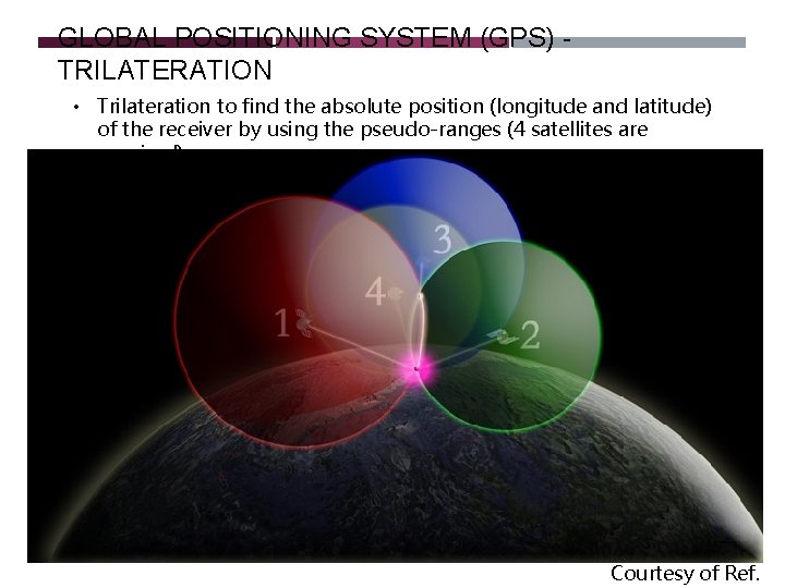
GLOBAL POSITIONING SYSTEM (GPS) • Trilateration to find the absolute position (longitude and latitude) of the receiver by using the pseudo-ranges (4 satellites are required)
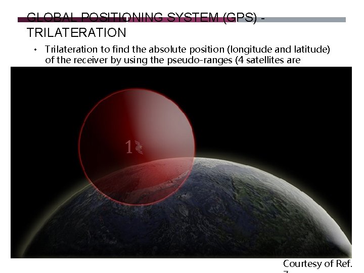
GLOBAL POSITIONING SYSTEM (GPS) TRILATERATION • Trilateration to find the absolute position (longitude and latitude) of the receiver by using the pseudo-ranges (4 satellites are required) Courtesy of Ref.
GLOBAL POSITIONING SYSTEM (GPS) TRILATERATION • Trilateration to find the absolute position (longitude and latitude) of the receiver by using the pseudo-ranges (4 satellites are required) Courtesy of Ref.
GLOBAL POSITIONING SYSTEM (GPS) TRILATERATION • Trilateration to find the absolute position (longitude and latitude) of the receiver by using the pseudo-ranges (4 satellites are required) Courtesy of Ref.
GLOBAL POSITIONING SYSTEM (GPS) TRILATERATION • Trilateration to find the absolute position (longitude and latitude) of the receiver by using the pseudo-ranges (4 satellites are required) Courtesy of Ref.
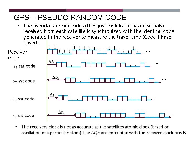
GPS – PSEUDO RANDOM CODE • The pseudo random codes (they just look like random signals) received from each satellite is synchronized with the identical code generated in the receiver to measure the travel time (Code-Phase based) Receiver code … … …
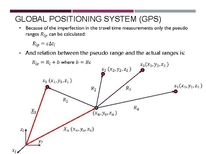
GLOBAL POSITIONING SYSTEM (GPS) • And relation between the pseudo range and the actual ranges is:
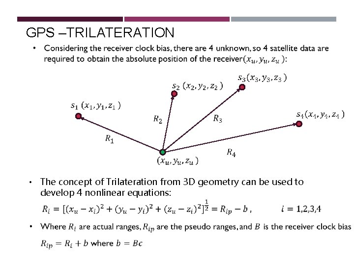
GPS –TRILATERATION • The concept of Trilateration from 3 D geometry can be used to develop 4 nonlinear equations:
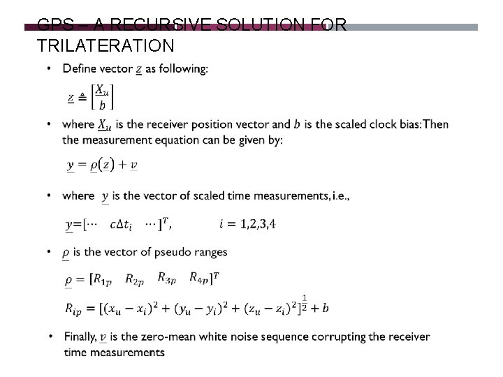
GPS – A RECURSIVE SOLUTION FOR TRILATERATION
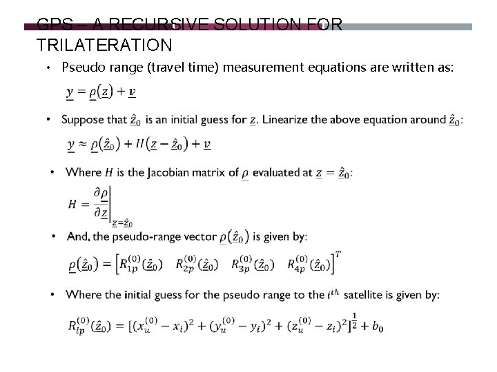
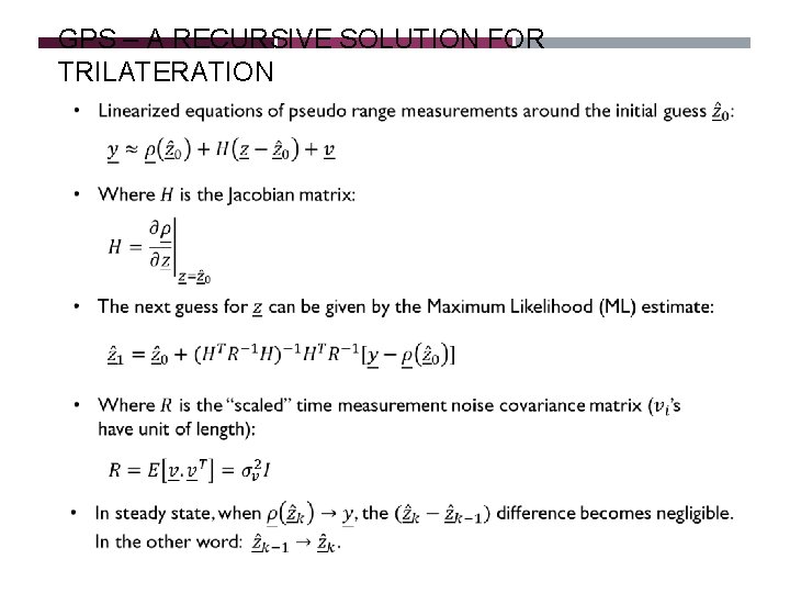
GPS – A RECURSIVE SOLUTION FOR TRILATERATION • Pseudo range (travel time) measurement equations are written as:
GPS – A RECURSIVE SOLUTION FOR TRILATERATION
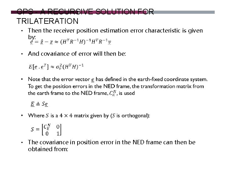
GPS - A RECURSIVE SOLUTION FOR TRILATERATION • Then the receiver position estimation error characteristic is given by: • And covariance of error will then be: • The covariance in position error in the NED frame can then be obtained from:
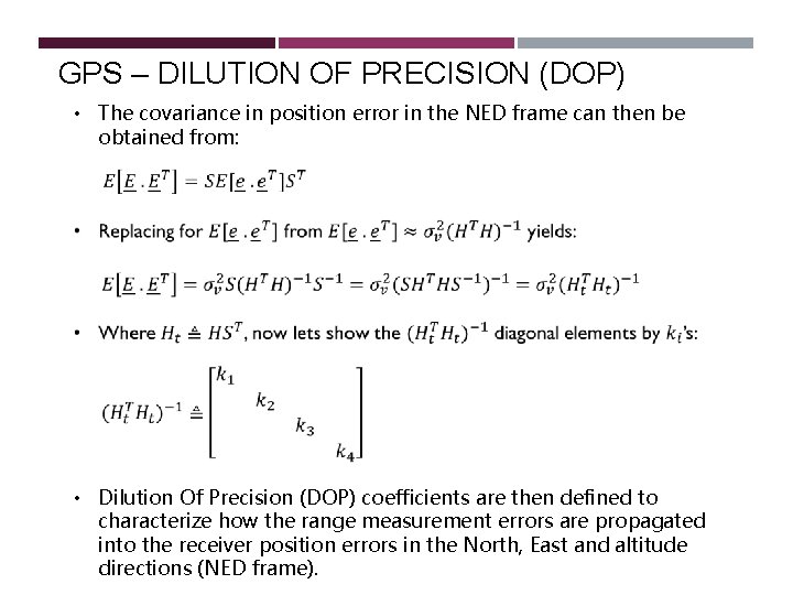
GPS – DILUTION OF PRECISION (DOP) • The covariance in position error in the NED frame can then be obtained from: • Dilution Of Precision (DOP) coefficients are then defined to characterize how the range measurement errors are propagated into the receiver position errors in the North, East and altitude directions (NED frame).
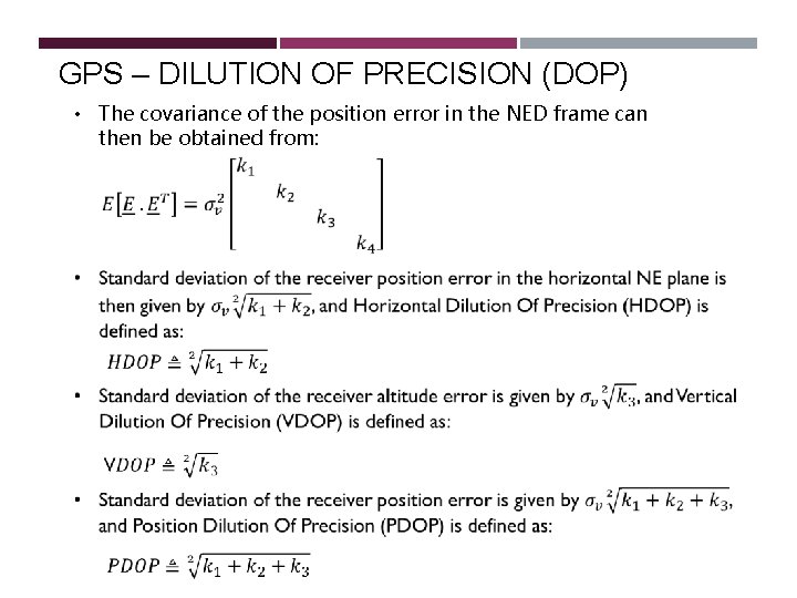
GPS – DILUTION OF PRECISION (DOP) • The covariance of the position error in the NED frame can then be obtained from:
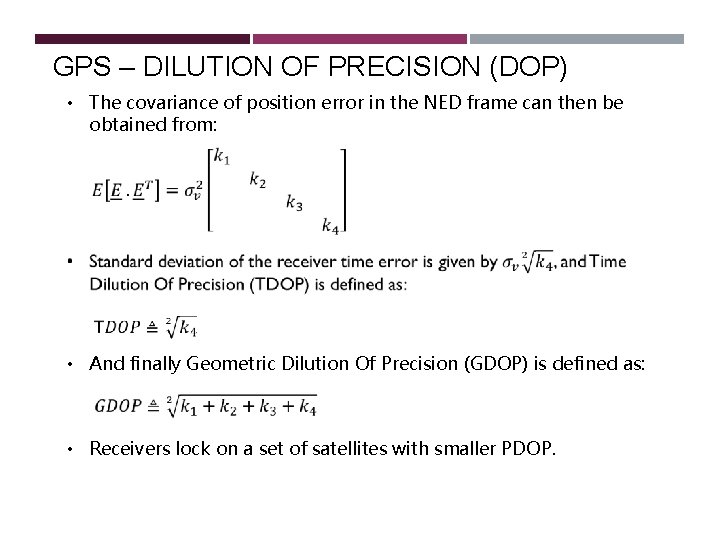
GPS – DILUTION OF PRECISION (DOP) • The covariance of position error in the NED frame can then be obtained from: • And finally Geometric Dilution Of Precision (GDOP) is defined as: • Receivers lock on a set of satellites with smaller PDOP.
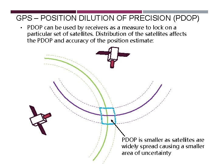
GPS – POSITION DILUTION OF PRECISION (PDOP) • PDOP can be used by receivers as a measure to lock on a particular set of satellites. Distribution of the satellites affects the PDOP and accuracy of the position estimate: PDOP is smaller as satellites are widely spread causing a smaller area of uncertainty
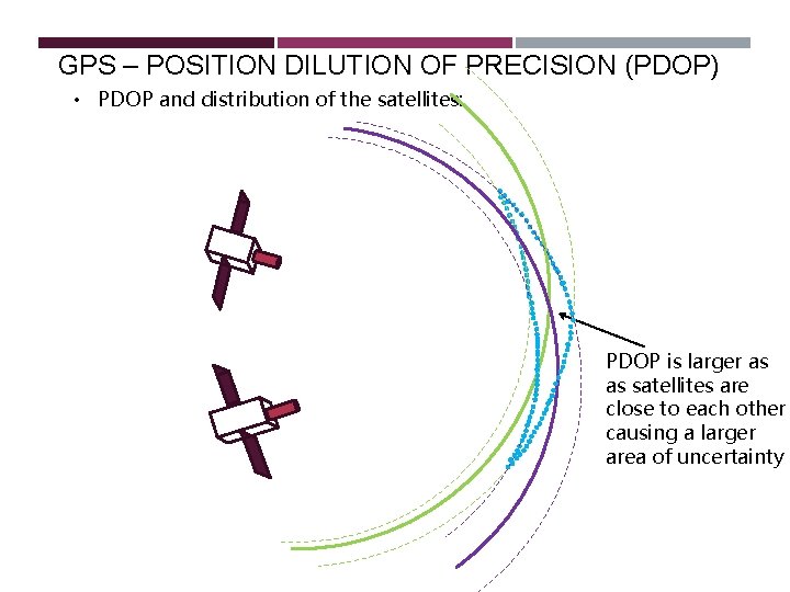
GPS – POSITION DILUTION OF PRECISION (PDOP) • PDOP and distribution of the satellites: PDOP is larger as as satellites are close to each other causing a larger area of uncertainty
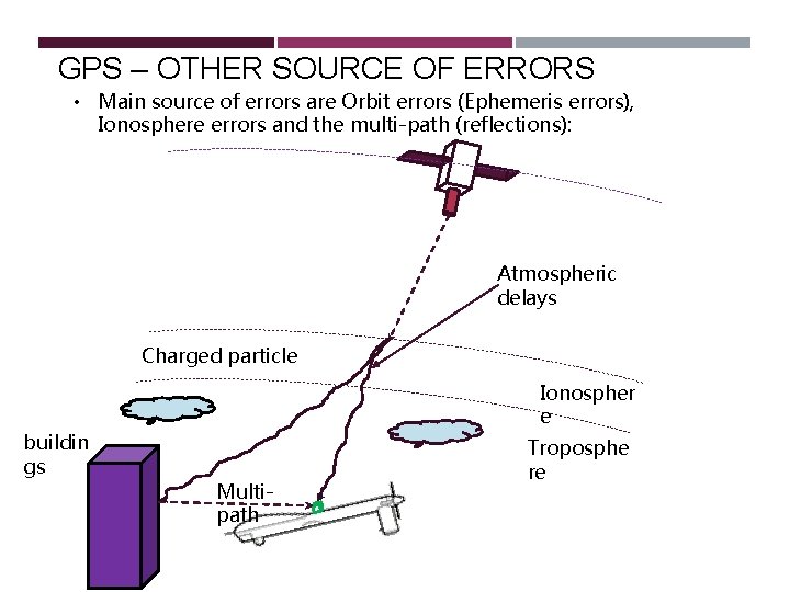
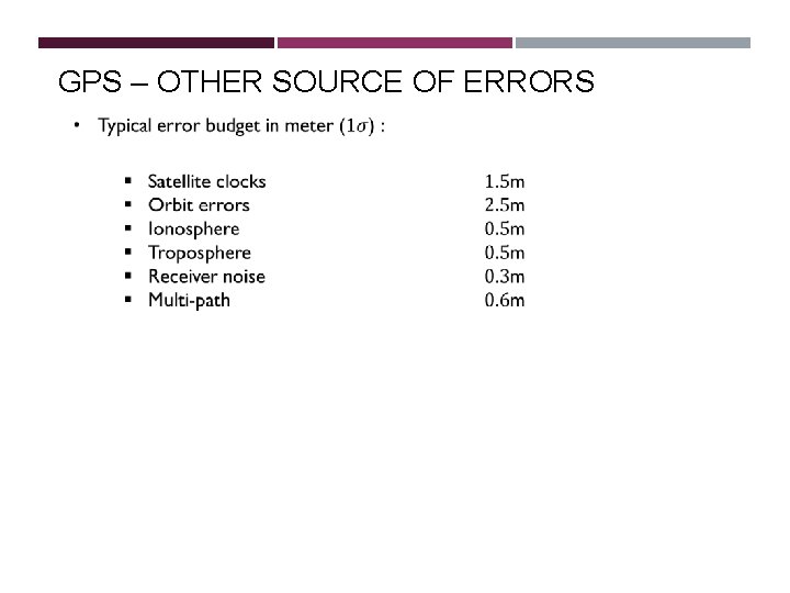
GPS – OTHER SOURCE OF ERRORS • Main source of errors are Orbit errors (Ephemeris errors), Ionosphere errors and the multi-path (reflections): Atmospheric delays Charged particle Ionospher e buildin gs Multipath Troposphe re
GPS – OTHER SOURCE OF ERRORS
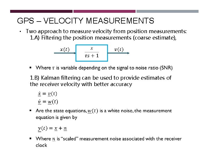
GPS – VELOCITY MEASUREMENTS • Two approach to measure velocity from position measurements: 1. A) Filtering the position measurements (coarse estimate), 1. B) Kalman filtering can be used to provide estimates of the receiver velocity with better accuracy
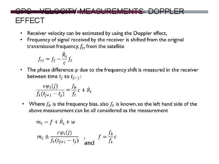
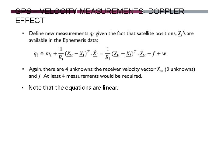
GPS – VELOCITY MEASUREMENTS- DOPPLER EFFECT , and
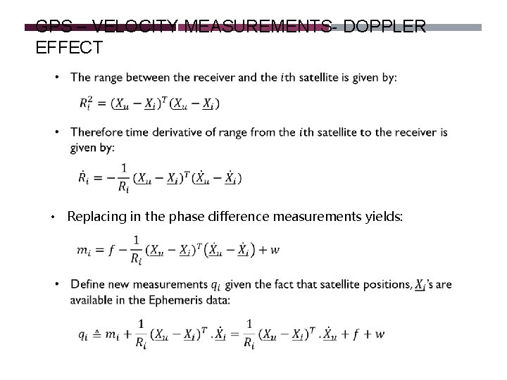
GPS – VELOCITY MEASUREMENTS- DOPPLER EFFECT • Replacing in the phase difference measurements yields:
GPS – VELOCITY MEASUREMENTS- DOPPLER EFFECT • Note that the equations are linear.
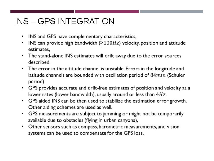
INS – GPS INTEGRATION
REFERENCES 1. A. Lawrence, Modern Inertial Technology, Springer, 1998 2. R. P. G. Collinson, Introduction to Avionic Systems, third edition, Springer. 3. D. H. Titterton and J. L. Weston, Strapdown Inertial Navigation Technology, Peter Peregrinus, Ltd. , 1997. 4. O. J. Woodman, An Introduction to inertial navigation. Technical Report, University of Cambridge, 2007. 5. IEEE Std 962 -1997 (R 2003) Standard Specification Format Guide and Test Procedure fro Single-Axis Interferometric Fiber Optic Gyros, Annex C. IEEE, 2003. 6. www. ett. bme. hu/memsedu 7. R. W. Beard, T. W. Mclain, Small Unmanned Aircrafts, Theory and Practice, Princton University Press, 2012. 8. GPS tutorial of National Geodetic Survey – National Oceanic and Atmospheric Administration