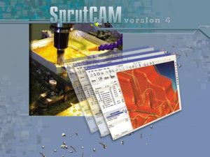
Sprut CAM features Main ontents Contents Sprut CAM


- Slides: 50

Sprut. CAM features Main сontents Contents

Sprut. CAM user interface Main menu Mode switch panel Main panel Viewport Standart view vectors panel Current mode panel Object visibility panel Sprut. CAM user interface is focused on the current task providing full information required on the current stage of project development and hiding all unrelated data Main сontents Contents

Milling tool Draft of tool and toolholder Spherical Cylindrical Tool profile Toroidal Double radial Tool libraries Limited double radial Conical Sprut. CAM supports all kinds of milling tools. User can create his personal tool libraries. Limited conical Engraver Negative radius Shaped form Main сontents Contents

Shaped tool creation Tool profile Type and name of new tool Profile definition code Save tool profile Tool parameters dialog for the 2 D Contouring operation Main сontents Contents

MIlling tools T-slot cutters are used to machine such part elements as grooves and slots Groove machining using T-slot mill Negative radius mill machining to form rounded edge Negative radius mills are used to machine edges and other elements with specified rounding Main сontents Contents

Collision detection Fixture contacting the machined part Sprut. CAM provides convenient tool to create solid fixtures, which can be stored in a library Toolpath element on which the collision of the fixture and the part occurred. Sprut. CAM hints what kind of error is reported Toolpath While toolpath is calculated Sprut. CAM automatically controls fixture and part collisions on all steps of machining Main сontents Contents

Lathe tool Tools library Operation type Workpiece material Machining conditions Lathe tool selection is simplified with special filter. Sprut. CAM automatically selects appropriate tool from users tools library considering machined material, type and parameters of machining Main сontents Contents

Lathe machining Toolpath Part 3 D model and Workpiece of the part, contoursby rotating a 2 D created contour Example of toolpath calculation of lathe machining including roughing, finishing, drilling and beveling operations Optimal technology selection is based on the part design, workpiece geometry and machining conditions Machining simulation Main сontents Contents

Pocketing operation Toolpath Plane Result text ofofdrafted simulation the pocketing in the of the operation Pocketing is Sprut. CAM calculated operation bounded 2 D on geometry a cylinder by closed editor surface curves considering the cylindrical base surface New grahical engine simulates the machining with high precision to visually follow the whole process of machining Result of of Toolpath simulation the Engraving of the operation Engravingover a cylinder on operation surface a cylinder surface Main сontents Contents

Milling operations Roughing operations Waterline Finishing operations Waterline Rest machining operations Combined Wateline Plane Flat land Plane Drive Wall machining Drive Pocketing Complex 2. 5 D contouring Complex Hole machining Optimized plane 3 D contouring Optimized plane 2. 5 D pocketing Engraving 2. 5 D Chamfer machining Pocketing Main сontents Contents

Option of the equipment Multi axis machine Scheme of the machine Stand Linear type slide (axis Y) Cross-slide box (axis Z) Rotary head (axis B) Rotary head (axis А) Spindle The tool Cross slide ( axis X) Graphic interpretation of the scheme of the machine in Sprut. CAM Rotary table (axis C) Workpiece The description of kinematics of the machine tool is accessible in format XML (a text file). The qualified user can independently describe the scheme of the machine and add it in library. It has no restriction on quantity of units and controlled axes. Main сontents Contents

Sprut. CAM machine structure 10 9 8 7 6 3 2 1 5 1. Workpiece 2. Spindle 3. Lunette 4. Support 5. Axial support 6. Radial support 7. Vertical support 8. Tool head 9. Tools 10. Casing 4 Example of machine scheme composed of several structural elements (marked by different colours). Each element has it’s own set of parameters that control positioning while machining and visualization while simulating Result of simulation Main сontents Contents

Parametres of 5 axis strategy Contact by a tool end face Contact by a side surface of the tool The way of contact of the tool with a surface of part can be made an end face of the tool, a site surface of the tool, or with the fixed position of an axis of the tool Main сontents Contents

Strategy of 5 axis machining by isoparametrical lines UV gives the chance to increase essentially productivity in typical cases, for example at the expense of processing of facets by a side surface of a cylindrical mill, machinings radius roundings off the corresponding tool. Removal of the material by side surface of a cylindrical mill along a fragment wall molded forms of a wheel disk Main сontents Contents

Types of the multi axis machines Variants of machines Classes of the machines • • The turning centres Controlled axis Up to 4 х capstans Drive the tool in the revolving head Program-controlled steady rest Opposite spindle Controlled tailstock Mechanisms of a loading - unloading Mechanisms of removal of a shaving Up to 15 The vertical and horizontal centres • Rotary and globe tables for changes of position of workpiece • Rotary the head for change of an axis rotations of the tool • Multi spindles • Tool bank for automatic change the tool • Pallets and other The multi-purpose (turning-milling) centres • Up to 4 х capstans • The milling head with moving on 4 axis • Other equipment inherent turning and to the milling centers Main сontents Up to 10 Up to 30 Contents

Machine schemes HURCO VTXU DMU 60 VMX Mori Seiki NL 2500 DMU 60 DECKEL MAHO Main сontents Contents

G-code calculation in machine coordinates Key advantage Sprut. CAM is possibility toolpath generation in coordinates of the concrete machine tool. It became possible thanks to application of the kinematic scheme the machine. Toolpath generation in coordinates of the concrete machine allows is realistic to visualise machine tool work as a whole. Universal the algorithm of recalculation of a toolpath in a machine tool axis forms optimum G-code even if the scheme describes the machine tool having more 5 axis operated. For reception of the G-code on other machine tool, it is enough to choose other scheme and to count toolpath. Thus, the postprocessor defines only syntax the G-code also does not make the geometrical calculations. The given fact minimises probability of occurrence Errors in Gcode after it has been checked in a Simulation mode. Main сontents Contents

Milling strategies Part machining project is composed of separate technology operations each of them providing set of machining parameters and produces toolpath according to designed strategy Main сontents Contents

Roughing machining Roughing waterline features clear flats option to machine material that is not cut by the part forming tool travel. Roughing plane operation features: • Optional upwards only travel along the Z axis within layer; • Optional control of max angle of cutting plunge along the Z axis; Main сontents Contents

Roughing drive operation Driving curve of the tool travel can be a user-defined contour or any edge curves of the machined part. Advantages of the roughing drive operation — low volumes of residual material and jagging-free machined surfaces. Main сontents Contents

Finishing drive machining Job Machined Toolpath assignment area by a driving curve Toolpath is calculated alogn the driving curves over the machined part’s surface. Edge curves of the machined model can be assigned as the driving curves. Tool travel along the outer edge of the part’s model Main сontents Contents

Complex machining Finishing plane Finishing waterline Residual material Finishing complex Residual material Main сontents Contents

Controlled scallop feature Residual material When scallop control option enabled, Sprut. CAM calculates toolpath for the operation considering the specified by the technologist maximum scallop value between nearing tool passes. The same area with the scallop option enabled Toolpath optimization is used to specify minimum allowed distance between passes to avoid excessive density of passes on some areas of the part Main сontents Contents

Optimized plane operation Finishing plane operation The plane operation leaves larger scallops on the plumb areas of the model. Optimized plane operation Optimized plane automatically assigns appropriate machining angles on special areas of the part to avoid scalloping. Main сontents Contents

Rest machining Finishing rest machining of residual material is used to achieve greater surface precision and reduce machining time. Residual material machining Sprut. CAM automatically detects unmachined areas. Use any finishing strategy to machine those areas. Main сontents Contents

Machining with restricted areas Restrictions model Machining result Workpiece model Part model Restrictions model Sprut. CAM supports machining with restricted areas. Restrictions can be defined by geometry models, 2 D geometry drafts, single surfaces or surface groups of the part itself. Main сontents Contents

Machining result with part compare Result Machining Initial Pocketing of the 3 D model use simulation operation of function result of visualization of stocks (dark blue sites signalize about presence of the remaining material in size more than 0, 1) Window of control parameter to visualizations remaining of the stocks Result of Toolpath Machining the useof of simulation machining function of ofthe visualization wall pocket’s machining beveled of stocks operation walls (blue by sites signalize the conical about mill presence of the remaining material in size more than 0, 01) The mechanism of comparison of workpiece with part of a detail allows to display evidently a remaining material allocating sites of a detail with various value of an stocks. The user can independently set values of stocks and tolerance of their display. Main сontents Contents

Rotary axis Sprut. CAM can produce NC-programs for machines equipped with rotarting heads or rotating tables. Rotary axes can be defined without machine element positions restrictions in the work area of the machine. Rotating toolhead Rotating table Rotary axis of rotating device can be specified either as a line parallel to one of coordinate axes and passing through specified point or a line passing through two points in the machine coordinate system. Main сontents Contents

Simulation engine Workpiece Toolpath Obtained Initial workpiece calculated of workpiece for after thethe pocketing simulation for next lathe-milling for after operation the operation of part pocketing previous regarding with the previous machining workpiece operation machining operations for as the next machining result of previous operations Machining result New simulation engine is used for both visual representation of machining allowing to preciselly track the process of workpiece transformation and to use the result of simulation in following operations as a workpiece allowing optimized toolpath calculation. Main сontents Contents

2. 5 D machining • Create 2 D model either by import or drafting it using built-ib 2 D geometry system. • Specify level and stock for model curves • Visualize 3 D view of the model • 2. 5 D Pocketing operation • 2. 5 D Wall machining operation Calculation View ofof technology work area Simulation Partresult draft operations considering given parameters • Hole machining operation Main сontents Contents

Geometry Measuring mode The interactive measures allows to determine geometrical characteristics of surfaces as models, and results of machining: the radiuses, the linear and angular sizes. As a rule, the received sizes are used for setting of parameters of the tool. In most cases now the geometrical model is enough for development of workflow. Main сontents Contents

2 D Geometry drafting 2 D Geometry mode Tools panel Item parameters panel 2 D Geomerty debugger tab Example of parametrized model 2 D Geometry layers tab 2 D Geometry parameters tab Main сontents Contents

Create contour by function Function definition Sprut. CAM can build contours or contour sections as mathematical functions specified by parametrical definition Main сontents Contents

2 D Geometry 3 D model snapping 3 D model snap Isometry view of the built contour Plane geometry drafting allows snapping to 3 D models points which eliminates errors in contour building. Main сontents Contents

Surface sewing Face Imported edgesmodel can be selected as job assignment or machined areas Surface sewing parameters Sew Faces Sewed surfaces Imported model’s faces sewing is useful to specify edges on surfaces joints for futher usage as job assignment. Main сontents Contents

Sections Properties of new section Preview of the section Section’s curves Intersect function to create sections A section is a parametrical element of the geometrical model. The section object is added into a folder of the geometrical tree to automatically receive intersection curves of all faces and meshes from the folder with the defined section plane. Main сontents Contents

Projection of model elements Properties of created projection Group of curves of projection Project function to create projections Selected surface Curves of the projection of element The function is used for the construction of outer enveloping projections of the selected surfaces and meshes onto the XY plane of the current coordinate system. In addition to surfaces borders the function allow to project ordinary curves on the plane. The curves it creates can be used when assigning parameters for machining operations. Main сontents Contents

Helical machining Tool travel parameters Simulation of helical machining Toolpath When helical machining is used to machine along flat curves Sprut. CAM forms toolpath helics along the Z axis whose projections to XY plane coincide with the machined curve. Optional finishing pass at bottom level along the whole curve is possible. Main сontents Contents

2. 5 D Pocketing and 2. 5 D Chamfering operations 2. 5 D pocketing Simulation result 2. 5 D Pocketing together with 2. 5 D Chamfering operations are used to machine metal parts and also wood basreliefs, ornamental designs and figures. A collection of plane curves is used as source model. Chamfer machining Main сontents Contents

Wall machining and Flat land machining operations Wall machining and Flat land machining are presented as separate operations with special parameter sets. This greatly simplified designing of technology developing and operation’s parameters specification. Flat land machining Main сontents Contents

Engraving operation Engraving machining uses plane designs imported from external CAD systems or drafted with the Sprut. CAM 2 D Geometry. 3 D processing of edges 3 D Toolpath option is used to form sharp edges when machining. For higher quality side surfaces engraving can be machined by layers. Main сontents Contents

2 D Geometry Text value memo Linear or radial text positioning Create Text function Text preview Text parameters tabs Main сontents Contents

Line and Circle definition Example of linear text positioning Line definition Example of circle text positioning Circle definition Main сontents Contents

Font and Style Font properties tab Font samples Font style properties Style examples Main сontents Contents

Hole recognition Simulation Toolpath result Sprut. CAM automatically finds holes in the part model and determines their parameters (coordinates, diameter, depth) and properties (blind/through, beveled). Hole recognition parameters Holes are sorted by diameter and automatically added to respective machining operations. Main сontents Contents

Technology summary Scheme of part setup on the machine Sprut. CAM creates technology documentation of the program is created automatically. Tools Operations Main сontents Contents

Postprocessors Sprut. CAM built-in Postprocessor Generator is a powerful tool for the technologist. It allows convenient transfering of the NC-program to any CNC-system. Main сontents Contents

Examples of Sprut. CAM projects Technology of die punch machining Die mold Die punch Die casting product Main сontents Contents

Advantages of Sprut. CAM • Minimum labour content of the creation G-code • Convenience in use • Quick mastering (1 -2 days) • Integration with known CAD • Fast adjustment for any CNC • Minimal requirements to a PC configuration • Fast recoupment of capital investments • Training and support • Free updating within the version Sprut. CAM 7 Main сontents Contents ®

Table of contents 1. Overview of Sprut. CAM system 23. Controlled scallop feature 2. Sprut. CAM user interface 24. Optimized plane operation 3. Milling tool 4. Shaped tool creation 25. Rest machining 5. MIlling tools 27. Комплексная обработка 6. Collision detection 28. Machining result with part compare 7. Lathe tool 29. Simulation engine 8. Lathe machining 30. 2. 5 D machining 9. Pocketing operation 31. Geometry Measuring mode 45. Hole recognition 10. Milling operations 32. 2 D Geometry drafting 46. Technology summary 11. Option of the equipment 33. Create contour by function 47. Postprocessors 12. Sprut. CAM machine structure 34. 2 D Geometry 48. Examples of Sprut. CAM projects 13. Parametres of 5 axis strategy 35. Surface sewing 49. Advantages of Sprut. CAM 14. Strategy of 5 axis machining 36. Sections 15. Types of the multi axis machines 37. Projection of model elements 16. Machine schemes 38. Helical machining 17. G-code calculation 18. Milling strategies 39. Pocketing and Chamfering operations 40. Wall machining and Flat land machining operations 19. Roughing machining 41. Engraving operation 20. Roughing drive operation 42. 2 D Geometry 21. Finishing drive machining 43. Line and Circle definition 22. Complex machining 44. Font and Style 26. Machining with restricted areas Main сontents Contents
 Sprut technology
 Sprut cam
 國體eeclass
 External estop requested
 Cam and follower examples
 Chat sexcam
 Main contents
 What are the main features of analyzed system?
 Feature of drama
 What is characteristics of qualitative research
 Defining technical communication
 What are 10 physical features of europe?
 Main features of war communism
 Main features of action research
 Features of victorian novels
 Kothari commission (1964-66) on women education
 Features of a folk tale
 Characteristics of african folktales
 Main features of romantic poetry
 Features of hire purchase system
 Be going to
 Finding the main idea why were canals built?
 Void main int main
 Introduction for portfolio
 Deep perineal pouch contents
 Febrile non hemolytic transfusion reaction
 Ffp
Ffp Thoracic skin
 Triangle scarpa
 Anterior mediastinum
 The immortal life of henrietta lacks table of contents
 Medial lemniscus
 Intermuscular spaces of scapular region
 Ark of the covenant lampstand
 Comic book table
 Root of mesentery
 Mla table of contents
 Contents of stylistic lexis
 Front page of school magazine
 Examples of continuous variables
 Report appendix example
 Ffp vs platelets
 Subdivision of mediastinum
 Mediastinum vs pericardium
 Difference between abstract and introduction
 Persepolis table of contents with page numbers
 Persepolis table of contents
 Interactive notebook table of contents
 Cryoprecipitate contains
 Contents of interpeduncular fossa
 Structure of spermatic cord
