SKULL AND PNS PROJECTIONS DR MONICA PATIL Lines


 Fronto occipital")


 and determining")


- Slides: 46
SKULL AND PNS PROJECTIONS DR MONICA PATIL
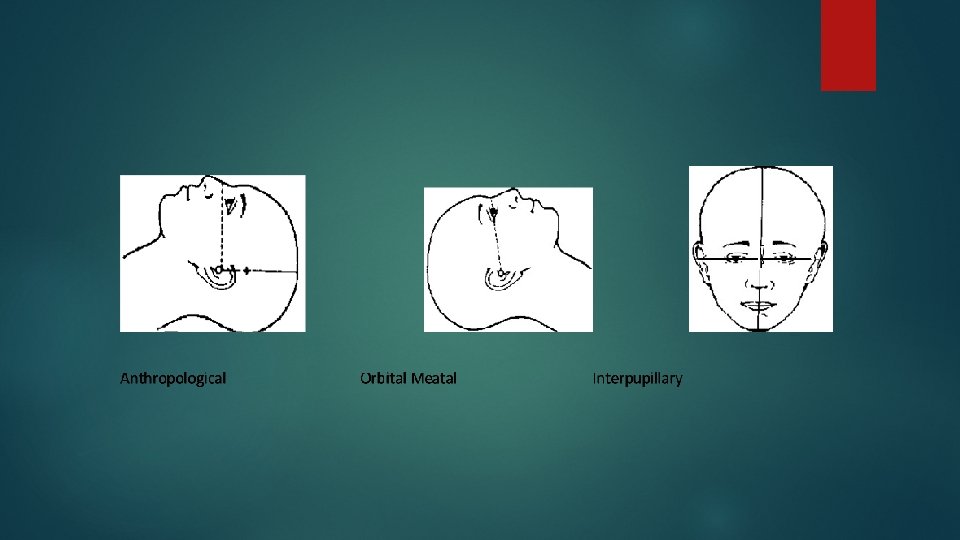
Lines Inter orbital line Infra orbital line Anthropological Orbito baseline meatal baseline
The Anthropological line The Isometric “Baseline” which runs from the inferior orbital margin to the upper border of the external auditory meatus (EAM) The Orbital-Meatal Line The original “Baseline” which runs from the outer canthus of the eye to the centre of the external auditory meatus The Interpupillary line The line connects the centres of the orbits and is at 90 degree to the median sagittal plane. NOTE: there is a difference of 10 to 15 degrees between the Orbital-Meatal line and the anthropological line.
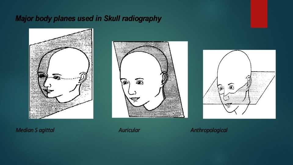
Planes Median sagittal plane Anthropological Auricular plane
The Median Sagittal plane. A vertical plane dividing the skull into 2 symmetrical right and left halves when viewed from the anterior aspect. The Anthropological plane This plane splits the skull into upper and lower halves passing along the anthropological baselines. The Auricular plane This plane divides the skull into anterior and posterior compartments along the Auricular lines.
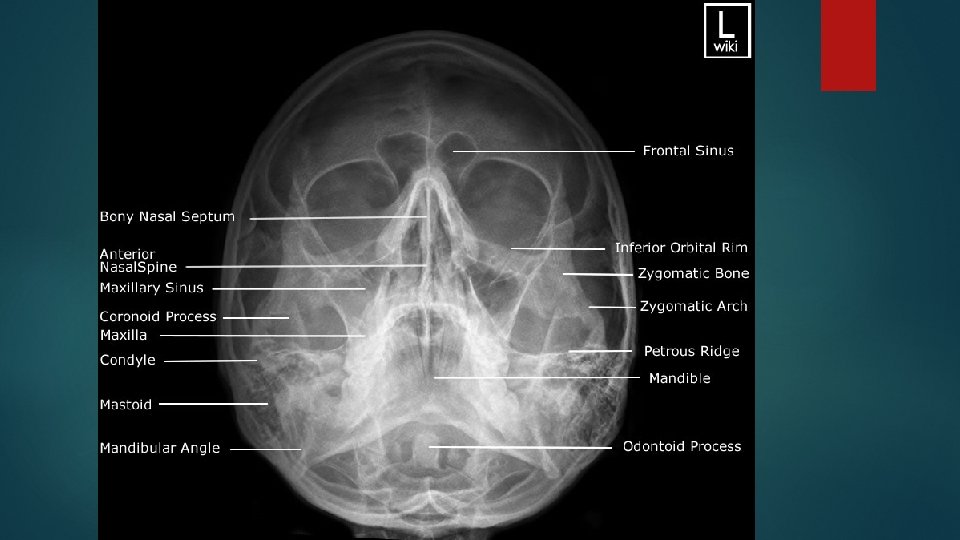
Basic views Lateral view Fronto occipital view ( A P view ) Fronto occipital with 30 deg caudad ( TOWNE’S view) Occipito frontal view ( P A view) Occipito frontal with 15 deg caudad ( CALDWELL’S Occipito mental view ( WATER’S view) view ) Submento vertical view (BASILAR view)
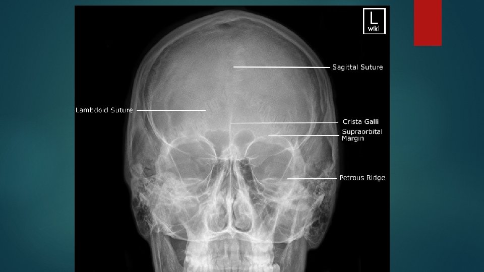
Occipito frontal view Positioning of patient : Patient is seated facing the erect bucky, so that the median sagittal plane is with the midline of the bucky and perpendicular to it. Neck is flexed to bring orbito meatal line perpendicular to the bucky, this can be achieved by ensuring the nose and forehead are in contact with the bucky.
Central ray : Ray is directed perpendicular to the bucky along the median sagittal plane and at the level of nasion. Image should include the vertex superiorly and base of occipital bone inferiorly
Caudal angulation : OF 0 deg : the petrous ridges completely superimposed with orbit OF 10 deg : the petrous ridges appears in the middle third of the orbit OF 15 deg : the petrous ridges appears in the lower third of orbit OF 20 deg : the petrous ridges appears just below the inferior orbital margin.
Fronto occipital view Positioning : Patient lies supine on a bucky table. Head is adjusted to bring the median sagittal plane at right angles to the film. The external auditory meatuses are equidistance from the cassette The orbito meatal baseline should be perpendicular to the cassette
Central ray : Central ray is directed perpendicular to the cassette along the medial sagittal plane and throw nasion. The field should be set to include the vertex of the skull superiorly and base of the occipital bone inferiorly.
Lateral view Position of patient : Patient sits facing the bucky and the head is then rotated, such that the median sagittal plane is parallel to bucky and inter orbital line is perpendicular to it. Position the cassette transversely in the erect bucky, such that its upper border is 5 cm above the vertex of the skull
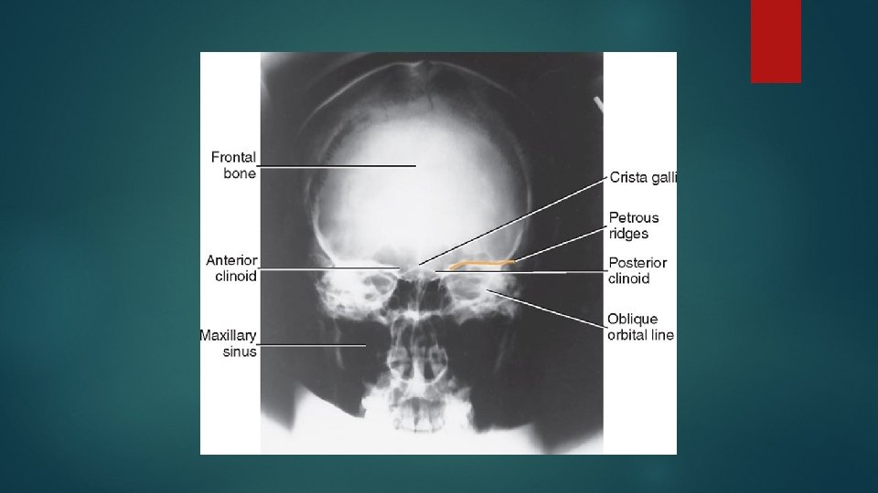
Central ray : midway between the glabella and the external occipital protuberance to a point approx 5 cm superior to the external auditory meatus. Essential image characteristics : The image should contain all cranial bones and the first cervical vertebra. Should superimpose the floor of anterior cranial fossa and posterior cranial fossa. The sella turcica and clinoid processes should also be superimposed.
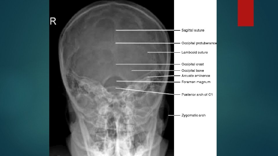
Towne’s view fronto occipital 30 deg caudad Positioning same as AP view Certral ray : Its angled caudally so it makes 30 deg to the orbito meatal plane Centre in the midline such that the beam passes midway between external auditory meatuses. This is a point approx 4 cm above the glabella
Essential image characteristics the sella turcica is projected with in the foramen magnum. Include all the occipital bone and posterior parts of parietal bone, and the lambdoid suture should be visualized clearly.
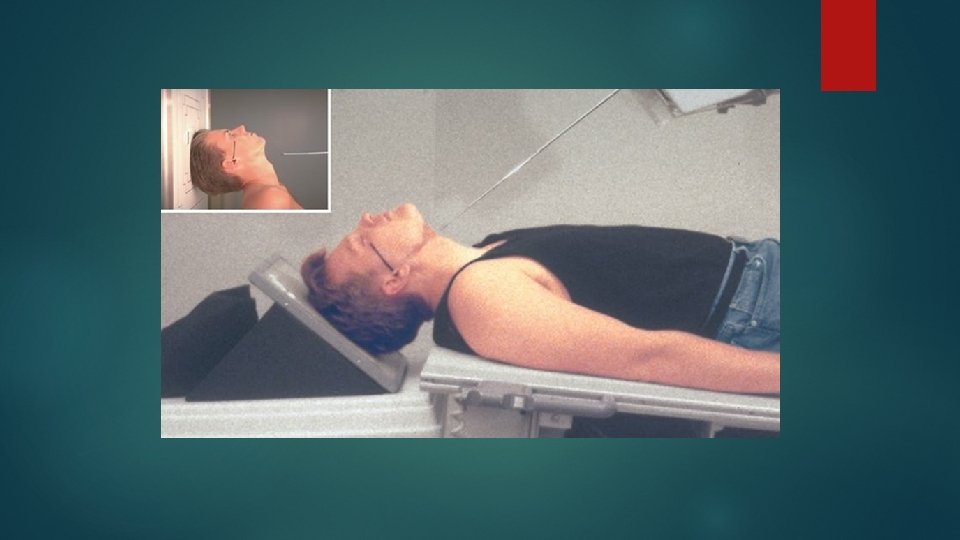
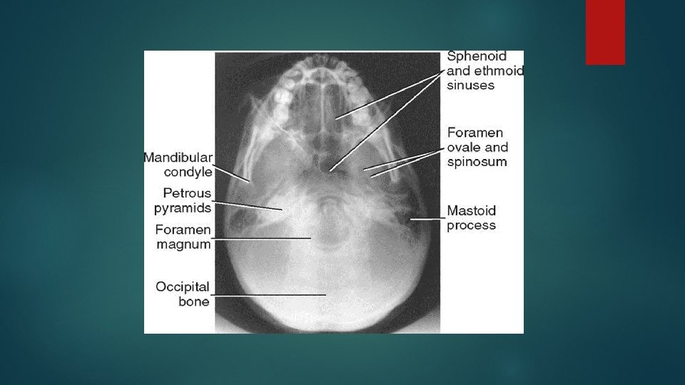
Submento vertical view Positioning of patient : Patient neck is hyperextended to bring the vertex in contact with the cassette. The median sagittal plane should be right angle to the cassette. The orbito meatal plane should be near as possible and parallel to the cassette.
Central ray : Central ray is perpendicular to orbito meatal line. Center 1½ inch (4 cm) inferior to the mandibular symphysis
Essential image characteratics : Should show the angles of mandible clear of the petrous portion of temporal bone. The formina of the middle cranial fossa should be seen symmetrically either side of the midline.
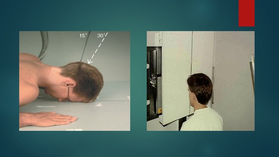
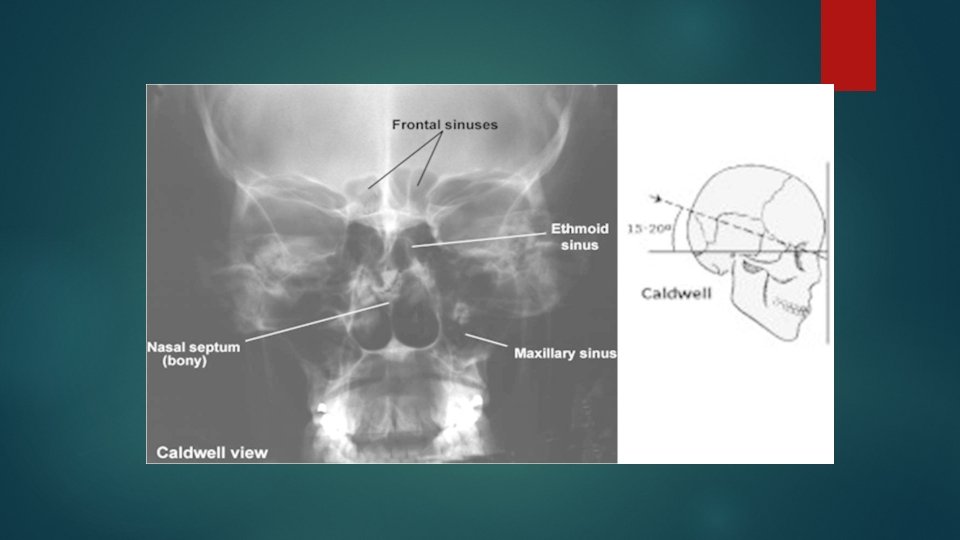
Caldwell’s view occipito frontal with 15 deg caudad Positioning same as occipito frontal view Central ray : Ray is directed perpendicular to the bucky along the median sagittal plane. The tube is rotated 15 deg caudal to the orbito meatal baseline
Alternate 25° to 30°: An alternate projection is a 25° to 30° caudad tube angle that allows better visualization of the superior orbital fissures (black arrows), the foramen rotundum (small white arrows), and the inferior orbital rim region. CR exits at level of nasion.
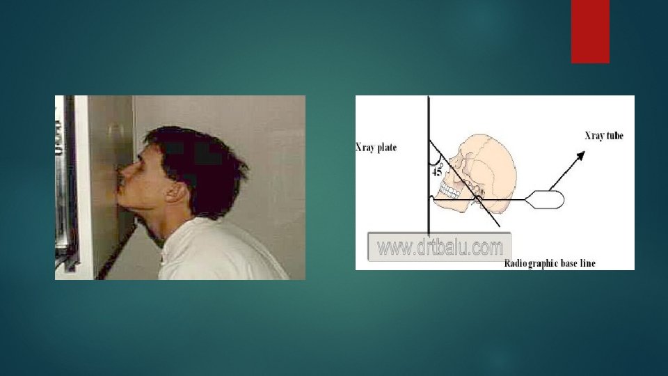
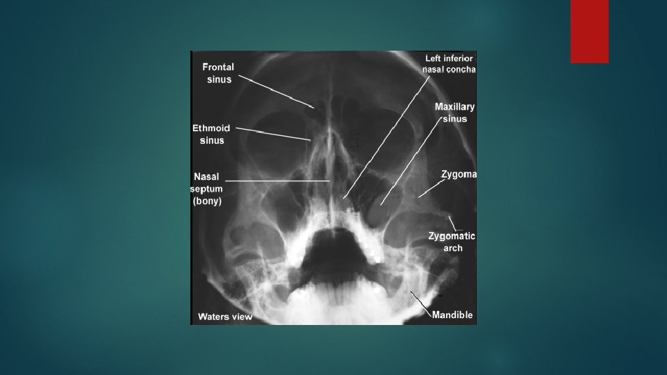
Occipito mental view WATER’S VIEW Positioning of patient The : patient is made to sit facing the cassette. Head is adjusted to bring orbito meatal line to 45 deg to the cassette The patient’s nose and chin are placed in contact with the midline of cassette. The patient should open the mouth as wide as possible before exposure.
Central ray : The ray should is perpendicular to the median sagittal plan. The ray should be centre to pass throw the base of nose.
POSITIONING CONSIDERATIONS Erect versus Recumbent The erect position allows the patient to be quickly and easily positioned and permits the use of a horizontal beam. A horizontal beam is necessary to visualize any existing airfluid levels within the cranial or sinus cavities
Exposure Factors The principal exposure factors for radiography of the skull include the following: • Medium k. V (65 to 85 k. V film-based) (70 to 80 k. V digital radiography [DR] and computed radiography [CR]) • Small focal spot <250 m. A (if equipment allows) • Short exposure time
SID The minimum SID with the image receptor in the table or upright Bucky is 40 inches (100 cm). IR size— 24 × 30 cm (10 × 12 inches) Radiation Protection The best techniques for minimizing radiation exposure to the patient in skull radiography are to (1) use good collimation practices, (2) immobilize the head when necessary, minimizing repeats, and (3) center properly.
Gonadal shielding Generally, with accurate collimation, no detectable contribution to gonadal exposure occurs during radiography of the skull. However, lead shields should be used to reassure the patient
ALARA Following ALARA principles (exposure to patient As Low As Reasonably Achievable) and determining exposure factors (highest k. V and lowest m. As that will result in desirable image quality). An increase in k. V over film-screen imaging may be desirable, both for reducing patient exposure and for improving image quality. (Sufficient m. As is required to produce a high-resolution image. )
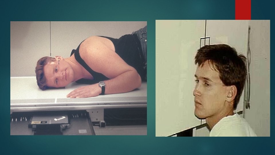
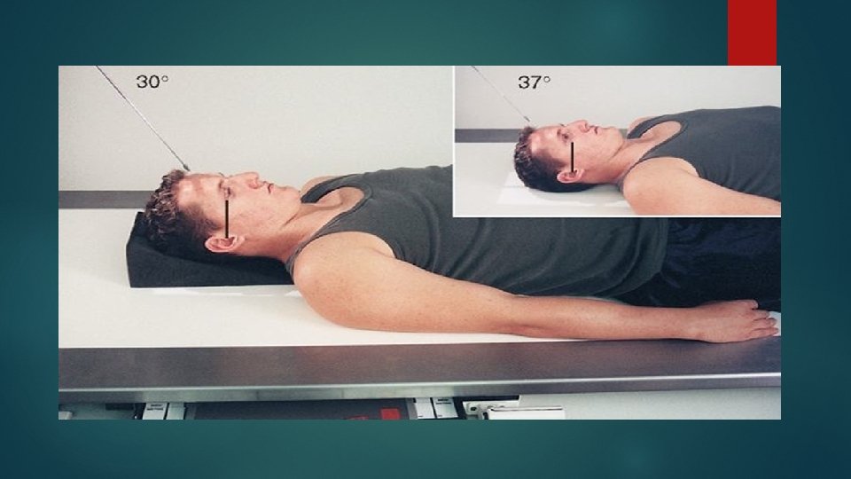
If patient is unable to depress the chin sufficiently to bring the OML perpendicular to the IR even with a small sponge under the head, the infraorbitomeatal line (IOML) can be placed perpendicular instead and the CR angle increased to 37° caudad. This maintains the 30° angle between the OML and the CR and demonstrates the same anatomic relationships. (A 7° difference exists between the OML and the IOML. )
Thank you!!!