ISOMETRIC PROJECTION RATHER DRAWING DEEPAK SAMEER JHA LOVELY


- Slides: 51
ISOMETRIC PROJECTION RATHER DRAWING DEEPAK SAMEER JHA LOVELY SCHOOL ENGINEERING
WHAT DO YOU UNDERSTAND LOOKING AT THE FIGURES SHOWN BELOW? SQUARE PLANE C Y L I ND E R RECTANGULAR PLANE C ON E CIRCULAR DISC
WHAT DO YOU UNDERSTAND BY? CUBE CUBOID
WHAT DO YOU UNDERSTAND BY? IT IS NOT VERY EASY AND SIMPLE TO INTERPRET AND UNDERSTAND THE ACTUAL COMPONENT BY LOOKING AT THE ORTHOGRAPHIC PROJECTION ALONE. SO WHAT DO WE NEED?
DESIGNER’S MIND MODEL NG I W A DR PRODUCER’S VIEW PRODUCER’S INTERPRETION OF THE DRAWING
PROJECTIONS: FOUR BASIC TYPES Note: Isometric is a special case of Axonometric Orthographic Projections Axonometric Pictorials Oblique Perspective
WHAT IS ISOMETRIC PROJECTION? ØIsometric projection is a type of an axonometric projection (or pictorial projection). Ø Isometric means ‘equal measure’. ØAs the name suggests, in isometric projection, all the mutually perpendicular plane surfaces of an object and the edges formed by these surfaces are equally inclined to a POP. Ø In isometric projection, only one view on a plane is drawn to represent the three dimensions of an object. This provides a pictorial view with a real appearance.
PRINCIPLE OF ISOMETRIC PROJECTION CUBE • Isometric means equal measure • All planes are equally or proportionately shortened and tilted • All the major axes (X, Y, Z) are 120 degrees apart
A VIDEO TO UNDERSTAND WHAT CONCEPT ARE WE ATTEMPTING TO UNDERSTAND
TERMINOLOGY Isometric axes The three lines GH, GF and GC meeting at point G and making 120° angles with each other are termed isometric axes. Isometric axes are often. The lines CB, CG and CD originate from point C and lie along X-, Y- and Z-axis respectively. The lines CB and CD make equal inclinations of 30° with the horizontal reference line. The line CG is vertical.
LETS STANDARDIZE THE AXES H LE NG E T AD TH HEIGHT BR
CHARACTERISTICS OF ISOMETRIC PROJECTION Isometric lines The lines parallel to the isometric axes are called isometric lines or isolines. A line parallel to the X-axis may be called an x-isoline. So are the cases of y-isoline and z-isoline. Non-Isometric lines The lines which are not parallel to isometric axes are called non-isometric lines or non-isolines. The face-diagonals and body diagonals of the cube shown in Fig. 18. 1 are the examples of non-isolines. Isometric planes The planes representing the faces of the cube as well as other faces parallel to these faces are called isometric planes or isoplanes. Note that isometric planes are always parallel to any of the planes formed by two isometric axes. Non-Isometric planes The planes which are not parallel to isometric planes are called nonisometric planes or non-isoplanes (or non-isometric faces). Origin or Pole Point The point on which a given object is supposed to be resting on the HP or ground such that the three isometric axes originating from that point make equal angles to POP is called an origin or pole point.
Making an Isometric Sketch • Defining Axis 60 o 30 o Isometric Axis
NOTE NO ISOMETRIC VIEW SHALL BE DRAWN WITHOUT DRAWING THE ORTHOGRAPHIC VIEWS
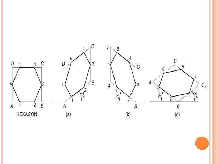
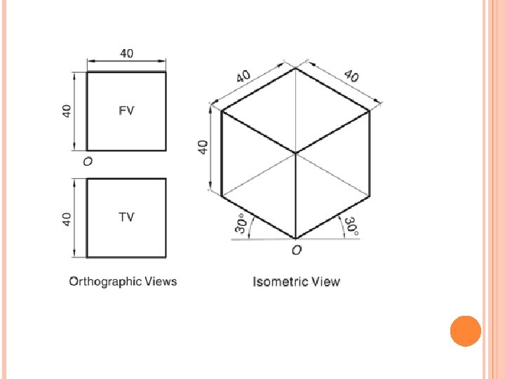
ISOMETRIC PROJECTION OF STANDARD FIGURES
RECTANGLE
TRIANGLE
PENTAGON
CIRCLE
IRREGULAR SHAPES
Using construction lines to construct a cube. Key rules! All diagonal lines are at 30°. All other lines are vertical. Keep all construction lines very faint.
Using a cube to create right angle triangles Other examples
SOLIDS PRISM PYRAMID OPPOSITE ENDS ARE EQUAL JOINED BY RECTANGULAR PLANES A PLANE ON ONE SIDE AND AN APEX ON THE OTHER JOINED BY TRIANGULAR PLANES Rectangular Prism (Cuboids) PENTAGONAL PRISM HEXAGONAL PRISM CYLINDER Rectangular Pyramid PENTAGONAL Pyramid HEXAGONAL Pyramid CONE
HEXAGONAL PRISM EDGE: 20 MM AND 50 MM HEIGHT
CYLINDER OF DIA 60 MM AND HEIGHT 80 MM
STEP 2 –ELLIPSE ON FRONT FACE - Corner to corner to get center - Lines to tangent points Tangent Points Lines to Tangent Points
STEP 3 –ELLIPSE ON FRONT FACE Sketch in Arcs Tangent Points
STEP 3 –ELLIPSE ON BACK FACE AND PROFILE Repeat for ellipse on rear face Draw Tangent Lines for Profile Complete Visible Part of Back Ellipse
A PENTAGONAL PYRAMID OF EDGE 30 MM AND HEIGHT 60 MM
A CONE OF DIA 60 MM AND HEIGHT 80 MM
Object for Practice
Blocking in the Object Begin with Front Face Height Width
Blocking in the Object: Add Side Face Height Depth
Blocking in the Object: Add Top Face
Adding Detail Cut Outs – Part 1
Adding Detail Cut Outs – Part 2
Adding Detail Cut Outs – Part 3
Darken Final Lines - Part 4 Note: All visible edges will be darkened
CHAPTER 4 : ISOMETRIC DRAWING 1. Three views of shaped block are shown in Figure 1. Draw a full size isometric view of the block in the direction of arrows shown. The size of grid is 10 mm x 10 mm. All hidden details need not be shown. FIGURE 1 LOCAL PUBLICATIONS (001427383 -A)
Sketch from an actual object STEPS 1. Positioning object. 2. Select isometric axis. 3. Sketch enclosing box. 4. Add details. 5. Darken visible lines.
Sketch from an actual object STEPS 1. Positioning object. 2. Select isometric axis. 3. Sketch enclosing box. 4. Add details. 5. Darken visible lines. Note In isometric sketch/drawing), hidden lines are omitted unless they are absolutely necessary to completely describe the object.
Sketch from multiview drawing 1. Interprete the meaning of lines/areas in multiview drawing. 2. Locate the lines or surfaces relative to isometric axis.
Example 1 : Object has only normal surfaces Top Regular H Top View Front View W Bottom View H W Side D Side View D Reverse Front Bottom Side
D Example 2 : Object has inclined surfaces Nonisometric line y H q y x Front View x W
Example 3 : Object has inclined surfaces x C x B A B x x A y C B A Nonisometric line
Example 4 Regular x y C D B B F Front View A C A E Reverse D F E
Circle & Arc in Isometric In isometric drawing, a circle appears as an ellipse. Sketching Steps 1. Locate the centre of an ellipse. 2. Construct an isometric square. 3. Sketch arcs that connect the tangent points.
Circle & Arc in Isometric Four-centre method is usually used when drawn an isometric ellipse with drawing instrument. Sketching Steps 1. Locate the centre of an ellipse. 2. Construct an isometric square. 3. Construct a perpendicular bisector from each tangent point. 4. Locate the four centres. 5. Draw the arcs with these centres and tangent to isometric square.
Example 5