SISTEMI DI LOCALIZZAZIONE 3 D Vincenzo Ferrari vincenzo


 and an emitter yield")


 embedded")


- Slides: 25
SISTEMI DI LOCALIZZAZIONE 3 D Vincenzo Ferrari vincenzo. ferrari@unipi. it
Marker-Based Tracking for Image-Guided Interventions Ziv Yaniv Sheikh Zayed Institute for Pediatric Surgical Innovation Children's National Medical Center Last updated: Sep. 17 2012
GPS is not for the Operative Room
Laparoscopic Navigator • G. Megali, V. Ferrari, C. Freschi, B. Morabito, F. Cavallo, G. Turini, E. Troia, C. Cappelli, A. Pietrabissa, O. Tonet, A. Cuschieri, P Dario F. Mosca: Endo. CAS navigator platform: a common platform for computer and robotic assistance in minimally invasive surgery. The international journal of medical robotics computer assisted surgery: MRCAS 2008; 4(3): 242 -51. Endo. CAS – University of Pisa, Italy
Laparoscopic Navigator
Motivation 1. Display a dynamic virtual replica of the real world on screen, facilitating understanding of current spatial relationships between objects and enabling the clinician to predict the consequences of motions.
Motivation 1. Display a dynamic virtual replica of the real world on screen, facilitating understanding of current spatial relationships between objects and enabling the clinician to predict the consequences of motions. 2. Automated tool positioning (robot end effector pose) using a prediction model based on current and previous poses of other tools and anatomical structures.
Motivation 1. Display a dynamic virtual replica of the real world on screen, facilitating understanding of current spatial relationships between objects and enabling the clinician to predict the consequences of motions. 2. Automated tool positioning (robot end effector pose) using a prediction model based on current and previous poses of other tools and anatomical structures. 3. User interaction.
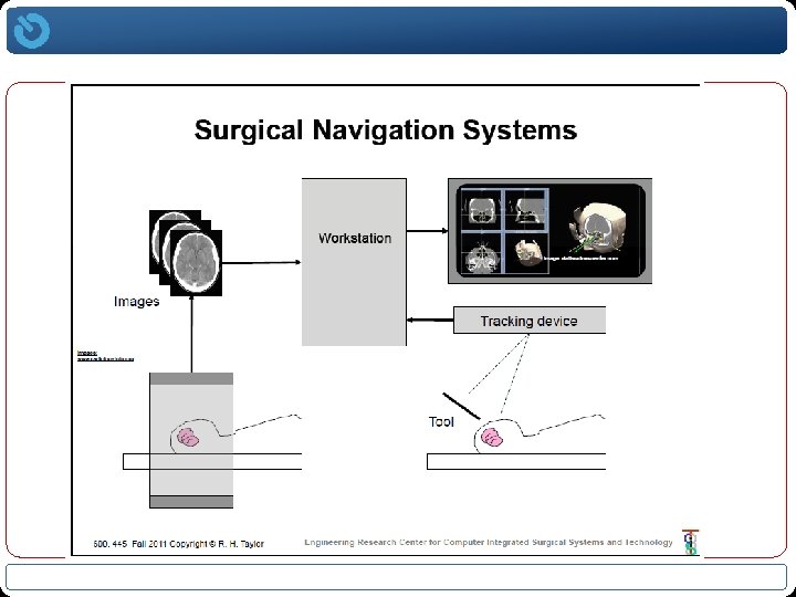
Spazi di lavoro e sottomoduli Work. Space Localizzatore Work. Space sala operatoria Calibrazione: determinare la rototraslazione che permette di sovrapporre il workspace di dispositivi rispetto a sistemi di riferimento noti Strumentazione tradizionale Work. Space robot Sistema di localizzazione Il localizzatore consente di effettuare misure 3 D della sala operatoria Paziente Reale Registrazione: determinare la trasformazione che consente di sovrapporre il “paziente virtuale” con il “paziente reale” Strumenti Robotici Work. Space dispositivo di imaging Immagini Pre/Intraoperatorie – “Paziente Virtuale”
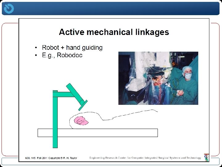
Mechanical Systems • Forward/Direct kinematics approach. • Encoders at the joints provide the relative translation and rotation. Refresh rate and latency ++ Concurrency --- Working volume - Obtrusiveness -- Completeness + Accuracy ++ Robustness ++ Cost - Pro: Highly accurate Con: Single object at a time Horsley-Clarke Frame Da-Vinci Robot Faro Arm e passivi obot) ch (r i iv tt a ia s o n Esisto
Horsley-Clarke Frame
Dime chirurgiche Endo. CAS – University of Pisa, Italy Vincenzo Ferrari
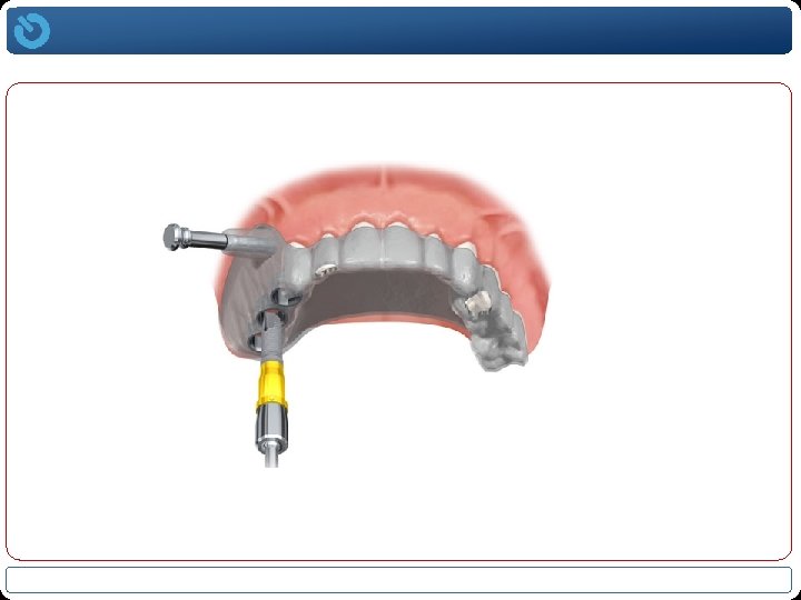
Surgical guide for dental implantology
Surgical guide for dental implantology Endo. CAS – University of Pisa, Italy Vincenzo Ferrari
Ultrasonic Systems • Trilateration approach. • Compute an emitter’s distance from a set of receivers at known locations. Distance obtained using the time it takes sound to reach the receiver from the emitter (TOF). Refresh rate and latency - Concurrency - Working volume + Obtrusiveness + Completeness + Accuracy + Robustness +- Cost - Pro: Unobtrusive. Con: Low refresh rate. microphones mounted on operating light: “A Frameless Stereotaxic Operating Microscope for Neurosurgery”, E. M. Friets et al. , IEEE Trans. Biomed. Eng. , vol. 36(6), pp. 608 -617, 1989.
Ultrasonic Systems m 2 • A set of receivers (n>2) and an emitter yield a set of n quadratic equations: m 1 d 2 d 1 p d 3 • In 3 D when we have 3 receivers we can obtain two linear equations and a quadratic by subtracting the first equation from the other two: • Solve the two linear equations and obtain the x and y coordinates as a function of the z coordinate. Substitute back into the quadratic equation and obtain the z coordinate. m 3 “Efficient solution and performance analysis of 3 -D position estimation by trilateration”, D. E. Manolakis, IEEE Trans. Aerosp. Electron. Syst. , vol. 32(4), pp. 1239 -1248, 1996.
Ultrasonic Systems • Three possible solutions for z: – Imaginary solution, no intersection between the three spheres. – One solution, single intersection point. – Two solutions, two intersection points. • For n>3, create a set of linear equations and solve either in an exact manner (n=4) or using a least squares formulation (pseudo-inverse). • Mount 3 or more emitters on tracked object in a known spatial configuration, fire them one after the other with a minimal temporal separation that is greater then the time it takes to reach all receivers. • Once all emitters are localized estimate the transformation using analytic paired point registration.
Electromagnetic Systems • Inducing current via magnetic field. • AC or pulsed DC driven magnetic fields.
Electromagnetic Systems • Set of coils inside electromagnetic field generator. • Miniature coil(s) embedded in tools (5 DOF or 6 DOF). • Pulsed DC: sequence of static fields, pose obtained by measuring magnitude of sensor response to each field – problems with ferrous materials. • AC: repeated signal pattern on high frequency carrier wave, pose obtained by amplitudes of the received signals – problems with eddy currents and resulting magnetic fields. • There is a wireless transponder based system which is part of a radiotherapy system(Calypso Medical), but most are wired.
Electromagnetic Systems Refresh rate and latency + Concurrency + Working volume + Obtrusiveness + [depends on FG choice] Completeness + Accuracy + Robustness + Cost + Pro: Do not require line of sight. Con: Wired, and susceptible to transient distortions.
ESERCIZI o o Definire una trasformazione a partire dalla conoscenza di 3 punti Definire un sistema di riferimento note le matrici di trasformazione di 2 sensori a 5 dof