Shading I Shandong University Software College Instructor Zhou


- Slides: 63

Shading I Shandong University Software College Instructor: Zhou Yuanfeng E mail: yuanfeng. zhou@gmail. com 1

Objectives • Learn to shade objects so their images appear three dimensional • Introduce the types of light material interactions • Build a simple reflection model the Phong model that can be used with real time graphics hardware 2

Why we need shading Gouraud shading With Wireframe Texture Polygon With Simple shadow Lighting model With Specular lighting 3

Why we need shading • Suppose we build a scene using many polygons and color it with gl. Color. We get something like • Which is the best? 4

Shading • Why does the image of a real sphere look like Why? • Light material interactions cause each point to have a different color or shade • Need to consider Light sources Material properties Location of viewer Surface orientation 5

Scattering • Light strikes A Some scattered Some absorbed • Some of scattered light strikes B Some scattered Some absorbed • Some of this scattered light strikes A and so on 6

Rendering Equation • The infinite scattering and absorption of light can be described by the rendering equation Cannot be solved in general ways Ray tracing is a special case for perfectly reflecting surfaces • Rendering equation is global and includes Shadows Multiple scattering from object to object 7

Global Effects shadow multiple reflection translucent surface 8

Local vs Global Rendering • Correct shading requires a global calculation involving all objects and light sources Incompatible with pipeline model which shades each polygon independently (local rendering) • However, in computer graphics, especially real time graphics, we are happy if things “look right” Exist many techniques for approximating global effects 9

Light-Material Interaction • Light that strikes an object is partially absorbed and partially scattered (reflected) • The amount reflected determines the color and brightness of the object A surface appears red under white light because the red component of the light is reflected and the rest is absorbed • The reflected light is scattered in a manner that depends on the smoothness and orientation of the surface 10

Light Sources General light sources are difficult to work with because we must integrate light coming from all points on the source Light color: I = [Ir, Ig, Ib], RGB mode, CMY mode 11

Simple Light Sources • Point source Model with position and color Distant source = infinite distance away (parallel) I(p 0) = [Ir(p 0), Ig(p 0), Ib(p 0)] 12

Simple Light Sources • Easy to use (in computer) • Realistic is poor: • Image contrast is high, some parts are bright and others are dark; • In real world, the lights will be large. • We can add ambient light to solve this problem. penumbra 13

Simple Light Sources • Spotlight Restrict light from ideal point source Why use cos function? 14

Simple Light Sources • Infinite light: Sun light Just know the light direction; The intensity is constant. • Ambient light Same amount of light everywhere in scene Can model contribution of many sources and reflecting surfaces Ia = [Iar, Iag, Iab] the same value at each point on surfaces 15

Surface Types • The smoother a surface, the more reflected light is concentrated in the direction a perfect mirror would reflected the light • A very rough surface scatters light in all directions smooth surface rough surface translucent surface Such as mirrors Such as a wall Such as water 16

Phong Model • A simple model that can be computed rapidly • Has three components Diffuse Specular Ambient • Uses four vectors To light source To viewer Normal Perfect reflector 17

Ambient Light • Ambient light is the result of multiple interactions between (large) light sources and the objects in the environment • Amount and color depend on both the color of the light(s) and the material properties of the object • Add ka Ia to diffuse and specular terms = reflection coef intensity of ambient light 18

Diffuse Reflection • An ideal diffuse surface is, at the microscopic level, a very rough surface. • Chalk is a good approximation to an ideal diffuse surface. • Because of the microscopic variations in the surface, an incoming ray of light is equally likely to be reflected in any direction over the hemisphere. 19

Lambertian Surface(朗伯面) • Perfectly diffuse reflector • Light scattered equally in all directions • Amount of light reflected is proportional to the vertical component of incoming light reflected light ~cos qi = l · n if vectors normalized There also three coefficients, kr, kb, kg that show much of each color component is reflected, related with the materials 20

Lambert's Cosine Law • Lambert's law determines how much of the incident light energy is reflected. • Remember that the amount of energy that is reflected in any one direction is constant in this model. In other words, the reflected intensity is independent of the viewing direction. = Ipd cosq A q B C 21

Illumination effects • Shaded using a diffuse-reflection model,from left to right kd=0. 4, 0. 55, 0. 77, 0. 85, 1. 0. • Shaded using a ambient and diffuse-reflection model,Ia =Ilight = 1. 0, kd = 0. 4. From left to right ka=0. 0, 0. 15, 0. 30, 0. 45, 0. 60 22

Specular Surfaces • Most surfaces are neither ideal diffusers nor perfectly specular (ideal reflectors) • Smooth surfaces show specular highlights due to incoming light being reflected in directions concentrated close to the direction of a perfect reflection specular highlight 23

Ideal Reflector • Normal is determined by local orientation • Angle of incidence = angle of relection • The three vectors must be coplanar r = 2 (l · n ) n l l n i l r v How to compute r 24

Modeling Specular Relections • Phong proposed using a term that dropped off as the angle between the viewer and the ideal reflection increased Ir ~ ks I cosaf f shininess coef reflected incoming intensity absorption coef 25

The Shininess Coefficient • Values of a between 100 and 200 correspond to metals • Values between 5 and 10 give surface that look like plastic cosa f 90 f 90 26

Spheres shaded using phong illumination model 27

Refract light • Snell law • ηt, ηi are the refract factors 28

Refract factor 29

Distance Terms • The light from a point source that reaches a surface is inversely proportional to the square of the distance between them • We can add a factor of the form 1/(c 1+c 2 d. L+c 3 d. L 2) to the diffuse and specular terms • The constant and linear terms soften the effect of the point source 30

Light source attenuation(衰减) • I = Iaka+fatt. Ilightkd(N. L) fatt=1/d. L 2 fatt = (1/min((c 1+c 2 d. L+c 3 d. L 2), 1)); Distance 1 1. 375 1. 75 2. 125 2. 5 C 0 0 1 . 25 . 5 0 1 0 31

Light Sources • In the Phong Model, we add the results from each light source • Each light source has separate diffuse, specular, and ambient terms to allow for maximum flexibility even though this form does not have a physical justification • Separate red, green and blue components • Hence, 9 coefficients for each point source Idr, Idg, Idb, Isr, Isg, Isb, Iar, Iag, Iab 32

Material Properties • Material properties match light source properties Nine absorbtion coefficients • kdr, kdg, kdb, ksr, ksg, ksb, kar, kag, kab Shininess coefficient a 33

Adding up the Components For each light source and each color component, the Phong model can be written (without the distance terms) as I =kd Id l · n + ks Is (v · r )a + ka Ia For each color component we add contributions from all sources 34

Phong light model 35

Modified Phong Model • The specular term in the Phong model is problematic because it requires the calculation of a new reflection vector and view vector for each vertex • Blinn suggested an approximation using the halfway vector(分向量) that is more efficient 36

Calculating the reflection vector R =Ncosq + S =Ncosq + Ncosq - L =2 N (N. L) L Calculating N. H instead of R. V, in which H = (L+V)/|L+V| 2*b=a 37

Using the halfway angle • Replace (v · r )a by (n · h )b • b is chosen to match shineness • Note that halfway angle is half of angle between r and v if vectors are coplanar • Resulting model is known as the modified Phong or Blinn lighting model Specified in Open. GL standard 38

Example Only differences in these teapots are the parameters in the modified Phong model 39

Computation of Vectors • l and v are specified by the application • Can computer r from l and n • Problem is determining n • For simple surfaces, it can be determined but how we determine n differs depending on underlying representation of surface • Open. GL leaves determination of normal to application Exception for GLU quadrics and Bezier surfaces (Chapter 11) 40

Plane Normals • Equation of plane: ax+by+cz+d = 0 • From Chapter 4 we know that plane is determined by three points p 0, p 2, p 3 or normal n and p 0 • Normal can be obtained by p 1 n = (p 2 p 0) × (p 1 p 0) p 0 p 2 41

Normal to Sphere • Implicit function f(x, y. z)=0 • Normal given by gradient • Sphere f(p)=x 2 + y 2 + z 2 1=0 • n = [∂f/∂x, ∂f/∂y, ∂f/∂z]T = p 42

Parametric Form • For sphere x=x(u, v)=cos u sin v y=y(u, v)=cos u cos v z= z(u, v)=sin u • Tangent plane determined by vectors ∂p/∂u = [∂x/∂u, ∂y/∂u, ∂z/∂u]T ∂p/∂v = [∂x/∂v, ∂y/∂v, ∂z/∂v]T • Normal given by cross product n = ∂p/∂u × ∂p/∂v 43

General Case • We can compute parametric normals for other simple cases Quadrics Parameteric polynomial surfaces • Bezier surface patches (Chapter 11) 44

Polygonal Shading • Shading calculations are done for each vertex Vertex colors become vertex shades • By default, vertex shades are interpolated across the polygon: gl. Shade. Model(GL_SMOOTH); • If we use gl. Shade. Model(GL_FLAT); the color at the first vertex will determine the shade of the whole polygon 45

Flat shading • Normal is same in each polygon; • Infinite viewer; • Infinite light; • For flat shading, we only need compute the color of one point in this polygon. 46

Polygon Normals • Polygons have a single normal Shades at the vertices as computed by the Phong model can be almost same Identical for a distant viewer (default) or if there is no specular component Infinite viewer and light • Consider model of sphere • Want different normal at each vertex even though this concept is not quite correct mathematically 47

Characteristic • It’s bad for polygon approximate smooth surface. The color in polygons is different. 48

View of human • Mach band • How to avoid this band? We should use smooth shading. 49

Smooth Shading • We can set a new normal at each vertex • Easy for sphere model If centered at origin n = p • Now smooth shading works • Note silhouette edge 50

Mesh Shading • The previous example is not general because we knew the normal at each vertex analytically • For polygonal models, Gouraud proposed we use the average of the normals around a mesh vertex n = (n 1+n 2+n 3+n 4)/ |n 1+n 2+n 3+n 4| 51

Data structure for polygon • Search adjacent polygons for each vertex. 52

Shading models for Polygons 53

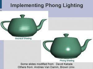
Two interpolated shading • Gouraud shading Cheap but gives poor highlights • Phong shading Slightly more expensive, but gives high quality highlights Flat Gouraud Phone 54

55

56

57

Gouraud V. S. Phong 58

Gouraud V. S. Phong 59

Gouraud and Phong Shading • Gouraud Shading Find average normal at each vertex (vertex normals) Apply modified Phong model at each vertex Interpolate vertex shades across each polygon • Phong shading Find vertex normals Interpolate vertex normals across edges Interpolate edge normals across polygon Apply modified Phong model at each fragment 60

Unrepresentative vertex normals 61

Sphere subdivision 62

Comparison • If the polygon mesh approximates surfaces with a high curvatures, Phong shading may look smooth while Gouraud shading may show edges • Phong shading requires much more work than Gouraud shading Until recently not available in real time systems Now can be done using fragment shaders (see Chapter 9) • Both need data structures to represent meshes so we can obtain vertex normals 63
 Shandong xiangguang group
 Gouraud shading
 詹景裕
詹景裕 Participante pasivo
 Tcole instructor course
 Basic instructor course texas
 Basic instructor course #1014
 Pepperball launcher nomenclature
 Neither of my two suitcases is adequate for this trip
 Instructor vs teacher
 Cisco certified instructor
 Mptc firearms instructor manual
 Tcole advanced instructor course
 Basic instructor course texas
 Virtual instructor.com
 Nfpa 1403 instructor to student ratio
 Tp 12863
 Instructor operating station
 Catia instructor
 Instructor
 Instructor responsibilities and professionalism lesson plan
 Tcole 1014 basic instructor course
 Njrotc instructor vacancies
 How to become an nrp instructor mentor
 Utp cable
 Cbrf registry wi
 Nra certified instructor logo
 Naismith was an instructor of
 Please clean your own room
 Tcole advanced instructor course
 Tcole advanced instructor course
 Jrotc marksmanship instructor course online
 15 sec illusion
 Cyan medical terminology
 Basic instructor course #1014
 Basic instructor course #1014
 Delmar cengage learning instructor resources
 Instructor office hours
 What is the mandate of heaven?
 The zhou dynasty ended in
 Pulse strecher
 Wenchao zhou
 Shuheng zhou
 Hwang ho civilization
 Huping zhou md
 Zhou dynasty facts
 Shang zhou qin han song
 Shang zhou qin han song
 Social structure of the song dynasty
 Zhou dynasty achievements
 6112006 color
 King cheng
 Ancient china zhou dynasty
 Mandate of heaven example
 Giulio zhou
 Yichao zhou
 China zhou dynasty
 China zhou dynasty
 Zhou dynasty wars
 Zhou dynasty map
 Xinan zhou
 Shurui zhou
 Weihua zhou
 Zhou wang
