Section 1 Theory of Heat Unit 3 Refrigeration


- Slides: 43

Section 1: Theory of Heat Unit 3: Refrigeration and Refrigerants

Unit Objectives After studying this chapter, you should be able to: n List three common refrigeration temperature ranges n Describe the term “ton of refrigeration” n Describe the basic refrigeration cycle n Explain the function of the compressor, condenser, metering device and evaporator n Explain the concepts of subcooling and superheat n List some desired refrigerant characteristics n Plot a system on a pressure enthalpy chart

INTRODUCTION TO REFRIGERATION n n n Cooling to preserve products and provide comfort 1900 s were the beginnings of mechanical refrigeration systems Refrigeration process temperature ranges High temperature – Air conditioning (comfort) n Medium temperature – Fresh food preservation n Low temperature – Frozen food preservation n

REFRIGERATION n n Process of transferring heat from a place where it is objectionable to a place where it makes little or no difference Heat naturally flows from a warmer substance to a cooler substance Heat will flow naturally from a 100°F house if the outside temperature is 80°F Mechanical refrigeration is needed if the house is 80°F and the outside temperature is 100°F

Heat flows naturally from a warmer substance to a cooler substance Outside temperature 80°F Inside Temp 100°F

Heat flows naturally from a warmer substance to a cooler substance Outside temperature 100°F Inside Temp 80°F Mechanical refrigeration would be needed to cool this house

RATING REFRIGERATION EQUIPMENT n n It takes 144 btu to melt one pound of ice at 32°F 2, 000 pounds of ice (1 ton) will require 288, 000 btu to melt (144 btu x 2, 000 pounds) If the melting of 1 ton of ice takes place in one day (24 hours), 12, 000 btu must be absorbed by the ice every hour (288, 000 btu / 24 hours) 12, 000 btu/hr = 200 btu/min = 1 ton of refrigeration

THE REFRIGERATION PROCESS n n n Heat is pumped from a cool box to a warm room Pumping of heat is similar to pumping water uphill Air conditioners pump heat from inside to the outside Inside temperature 75°F, Outside temperature 95°F n Cooling (indoor) coil temperature 40°F n Condenser (outdoor) coil temperature 125°F n Indoor heat travels to the indoor coil n System heat flows from the outdoor coil to the outside air n

Outdoor coil at 125°F Outside temperature 95°F Inside Temp 75°F Cooling coil at 40°F Heat flows naturally from the air inside the house to the cooling coil (evaporator) Heat also flows naturally from the condenser coil to the ambient air surrounding the coil

PRESSURE/TEMPERATURE RELATIONSHIP n n n Water boils at 212°F at atmospheric pressure (29. 92 in. Hg) Water boils at 250°F if pressure is increased to 15 psig Water boils at 40°F if pressure is reduced to 0. 248 in. Hg Refrigerants are substances that boil at low pressures and temperatures and condense at high pressures/temperatures Saturation temperature – Point at which the addition or removal of heat will result in a change of state During a change of state, the temperature remains constant

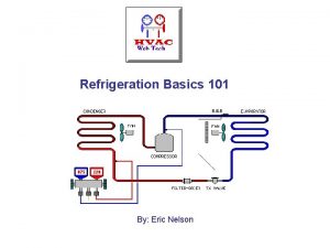
FOUR MAJOR REFRIGERATION SYSTEM COMPONENTS n n Evaporator - Absorbs heat from area to be cooled Compressor – Creates pressure difference needed to facilitate refrigerant flow through the system Condenser - Rejects system heat Metering device – Regulates refrigerant flow to the evaporator

THE EVAPORATOR n n Heat exchange surface used to absorb heat Located on the low-pressure side of the system between the metering device and the compressor Operates at temperatures lower than the medium being cooled or conditioned Absorbs heat by boiling a low temperature liquid into a low temperature vapor

THE EVAPORATOR (cont’d) n n Refrigerant typically enters the evaporator as a liquid/vapor mix (75% liquid, 25% vapor) Superheat n n n The heating of a vapor above its saturation temperature Ensures that no liquid refrigerant enters the compressor Equal to the evaporator outlet temperature minus the evaporator saturation temperature Design superheat is typically between 8°F and 12°F Superheated vapor does not follow a pressure/temperature relationship

AIR CONDITIONING APPLICATION: R-22 EVAPORATOR 68. 5 psig In green region, the P/T relationship does not hold 43°F 45°F 41°F 50°F Superheated vapor to the compressor Last drop of liquid 40°F 68. 5 psig (40°F from P/T chart) Liquid/vapor mixture from the metering device

THE COMPRESSOR n n n Pumps heat-laden vapor from the evaporator to the condenser by increasing the refrigerant pressure Reduces pressure on the low-side of the system Increases pressure on the high-side of the system Common compressor types include the scroll, reciprocating and the rotary Positive displacement compressors require that the compressed gas be moved to the

Low pressure, low temperature superheated vapor enters the compressor Refrigerant from the evaporator Suction line High pressure, high temperature superheated vapor leaves the compressor Refrigerant to the condenser Discharge line Refrigerant in the compressor is superheated, so it does not follow a pressure/temperature relationship!

THE CONDENSER n n n Rejects sensible and latent heat from the system that was absorbed by compressor and evaporator Located on the high-pressure side of the system The refrigerant condenses from a high temperature vapor to a high temperature liquid Condensing temperature is determined by the high side pressure in the system Refrigerant is subcooled at the outlet of the condenser

THE CONDENSER (cont’d) n Subcooling The cooling of liquid refrigerant below its saturation temperature n Standard air-cooled systems are designed to operate with a minimum of 10°F of subcooling n High efficiency condensers operate with more subcooling than standard efficiency systems n Determined by subtracting the condenser saturation temperature from the condenser outlet temperature n

AIR CONDITIONING APPLICATION: R-22 CONDENSER Refrigerant is desuperheating 226 psig In green regions, the P/T relationship does not hold 130°F 185°F 110°F 200°F Superheated vapor from compressor First drop of liquid 110°F 106°F 101°F Refrigerant is subcooling 98°F 95°F Subcooled liquid to the metering device

THE METERING DEVICE n n Controls the flow of subcooled liquid from the condenser to the evaporator Creates a pressure drop between the high and low pressure sides of the system About 25% of the liquid leaving the metering device immediately vaporizes (flash gas) Three commonly used metering devices are the capillary tube, automatic expansion valve and thermostatic expansion valve

PUTTING IT TOGETHER: A WINDOW UNIT EXAMPLE Compressor Condenser Indoors: 75°F Outdoors: 95°F Evaporator Metering device R-22

PUTTING IT TOGETHER: A WINDOW UNIT EXAMPLE 100% vapor 50°F 69 psig 200°F 278 psig 125°F Saturated refrigerant 110°F Outdoors: 95°F 278 psig 69 psig (40°F) 75% liquid 25% vapor R-22

PUTTING IT TOGETHER: A WINDOW UNIT EXAMPLE 50°F 69 psig 200°F 278 psig 125°F 110°F Superheat = 50°F - 40°F = 10°F Outdoors: 95°F Subcooling = 125°F - 110°F = 15°F 69 psig (40°F) R-22

REFRIGERANTS n n n R-12 used primarily for high and medium temperature refrigeration applications (manufacture banned in 1996) R-22 used primarily in air conditioning applications (slated for total phase-out in 2030) R-500 and R-502 banned in 1996 R-134 a – replacement for R-12 with retrofit Replacements for R-22 include R-410 a and R 407 c

REFRIGERANTS MUST BE SAFE n n n Designed to protect people from sickness, injury and death Proper ventilation is required Refrigerants can displace oxygen if permitted to accumulate Modern refrigerants are non-toxic When burned, toxic/corrosive gases are created

REFRIGERANTS MUST BE DETECTABLE Methods used for detecting refrigerant leaks include: n n n Soap bubble solution – pinpoints leaks Halide leak detector – uses an open flame Electronic leak detectors – general area leaks Ultraviolet leak detectors – pinpoints leaks Ultrasonic leak detectors – uses sound waves

GENERAL REFRIGERANT NOTES n n n Refrigerants should boil at low temperatures at atmospheric pressure so that low temperatures can be obtained without going into a vacuum It is illegal to intentionally vent refrigerant to the atmosphere (Stiff fines for violations) Mandatory certification for technicians The EPA set refrigerant phase-out schedules Refrigerant cylinders and drums are color-coded

RECOVERY, RECYCLING AND RECLAIMING OF REFRIGERANTS n n n Refrigerant recovery is mandatory during service and installation operations Intended to reduce the emissions of CFC, HCFC and HFC refrigerants Recovery equipment must be used according to manufacturer’s instructions

PLOTTING THE REFRIGERATION CYCLE n Pressure-enthalpy chart Used to create a graphical representation of a system n Pressure scales on the vertical axis (psia) n Enthalpy scale along the bottom of the chart n Horseshoe curve represents the saturation curve n Refrigerant is saturated on and under the curve n n Enthalpy is defined as heat content

THE PRESSURE ENTHALPY CHART Saturation curve Subcooled liquid region Pressure (psia) Saturated refrigerant Enthalpy scale (btu/lb) Superheated vapor region

THE PRESSURE ENTHALPY CHART: A SAMPLE PLOT Condenser Metering device Compressor Pressure (psia) Evaporator Enthalpy scale (btu/lb)

THE PRESSURE ENTHALPY CHART: AN R-22 EXAMPLE 311. 5 psia Cond. sat. temp. 130°F (296. 8 psig, 311. 5 psia)

THE PRESSURE ENTHALPY CHART: AN R-22 EXAMPLE 311. 5 psia 83. 2 psia Evap. sat. temp. 40°F (68. 5 psig, 83. 2 psia)

THE PRESSURE ENTHALPY CHART: AN R-22 EXAMPLE 130°F 311. 5 psia 83. 2 psia 0°F of subcooling, so refrigerant enters the metering device at 130°F 40 btu/lb

THE PRESSURE ENTHALPY CHART: AN R-22 EXAMPLE Evaporator superheat is 10°F, so refrigerant leaves 130°F evaporator at 50°F 311. 5 psia 50°F 83. 2 psia 40 btu/lb 110 btu/lb

THE PRESSURE ENTHALPY CHART: AN R-22 EXAMPLE Suction line superheat is 10°F, so refrigerant enters 130°F compressor at 60°F 311. 5 psia 60°F 83. 2 psia 40 btu/lb 112 btu/lb

THE PRESSURE ENTHALPY CHART: AN R-22 EXAMPLE 130°F Refrigerant leaves compressor at 190°F 311. 5 psia 83. 2 psia 127 btu/lb 40 btu/lb 112 btu/lb

THE PRESSURE ENTHALPY CHART: AN R-22 EXAMPLE 311. 5 psia 83. 2 psia 127 btu/lb 40 btu/lb 112 btu/lb

THE PRESSURE ENTHALPY CHART: AN R-22 EXAMPLE Metering device: “A to B” A Evaporator: “B to C” Suction line: “C to D” Compressor: “D to E” B E C Condenser “E to A” D 127 btu/lb 40 btu/lb 112 btu/lb

PRESSURE ENTHALPY CALCULATIONS n n Net Refrigeration Effect (NRE) = C – B = 110 btu/lb – 40 btu/lb = 70 btu/lb Heat of Compression (HOC) = E – C = 127 btu/lb – 110 btu/lb = 17 btu/lb Total Heat of Rejection (THOR) = E – A = 127 btu/lb – 40 btu/lb = 87 btu/lb Heat of Work = E – D = 127 btu/lb – 112 btu/lb = 15 btu/lb

UNIT SUMMARY n n Common refrigeration temperature ranges are high, medium and low High temperature refrigeration is also referred to as air conditioning or comfort cooling Refrigeration is the process of transferring heat from a place where it is objectionable to a place where it makes little or no difference Heat flows naturally from warm to cool substances

UNIT SUMMARY - 2 n n n Saturated refrigerants follow a P/T relationship One ton of refrigeration is equal to 12, 000 btu/hour The evaporator is the component that absorbs heat The condenser is the component that rejects heat The metering device is the component that regulates refrigerant flow to the evaporator The compressor creates the pressure difference in the system that allows the refrigerant to flow

UNIT SUMMARY - 3 n n n Superheat is equal to evaporator outlet temperature minus evaporator saturation temperature Subcooling is equal to the condenser saturation temperature minus the condenser outlet temperature Superheated and subcooled refrigerants do not follow a pressure/temperature relationship Modern refrigerants must be safe and detectable The pressure enthalpy chart provides a
 Plate type exchanger
 Refrigeration system design
 Introduction of refrigeration system
 Standard refrigeration heat exchanger
 Dtfd switch
 What is refrigerant glide
 Unit 36 refrigeration applied to air conditioning
 Refrigeration definition thermodynamics
 Unit 6 review questions
 Specific heat capacity graph
 Formula specific latent heat
 The three principles of cooking
 Non cyclic refrigeration
 Subcooling formula
 Refrigeration process
 Refrigerant cycle
 Refrigeration cycle cop
 Thermoacoustic refrigeration
 Refrigeration cycle ts diagram
 Adsorption system
 Bell coleman cycle process
 Air conditioning basics ppt
 Reverse refrigeration cycle
 Hawkes bay refrigeration
 Thermoacoustic refrigeration
 Commercial refrigeration troubleshooting
 Fridge thanda
 Refrigeration basics
 Polair refrigeration
 Matlab refrigeration cycle
 Codan ngt
 Parallel feed evaporator
 Orifce
 Principle of canning
 Magnetic refrigeration
 Advanced refrigeration technology
 Refrigration cycle
 Viroligy
 Multipurpose refrigeration systems with a single compressor
 Thermoacoustic refrigeration
 Refrigeration
 Refrigeration parts botswana
 Section 3 using thermal energy worksheet answer key
 Chapter 14 section 1 heat and temperature answers
