Gas Processing I NGT 140 Chapter 3 Dew


 •")
 •")
 recovery • Natural")
 • Glycol is used")
 • Joule-Thomson effect –")


 occurs when tubes are completely covered by refrigerant")


- Slides: 26
Gas Processing I NGT 140 Chapter 3 Dew Point Control And Refrigeration Systems “This product was funded by a grant awarded by the U. S. Department of Labor’s Employment and Training Administration. The product was created by the grantee and does not necessarily reflect the official position of the U. S. Department of Labor. The Department of Labor makes no guarantees, warranties, or assurances of any kind, express or implied, with respect to such information, including any information on linked sites and including, but not limited to, accuracy of the information or its completeness, timeliness, usefulness, adequacy, continued availability, or ownership. ” Unless otherwise specified, this work by Shale. NET U. S. is licensed under a Creative Commons Attribution 4. 0 International License.
Ch 3 Ch 5 Ch 2 Ch 7 & 8 Ch 4 Ch 10 Ch 6 Ch 9 Ch 2 Ch 9
• In Ch. 2 - Raw gas is gathered from wells and then goes through: • Feed gas receiving unit • Condensate stabilization unit • Then flows through a gas-treating unit to be covered in the next chapter (4) • Then to a dew-point control unit and refrigeration units covered in this chapter (3) • Refrigeration units also acts as a natural gas liquid (NGL) recovery units (Ch. 7)
Dew Point Control Unit • Helps prevent liquid condensation in the pipeline • There are two types of dew-point control required 1. Water dew-point control 2. Hydrocarbon dew-point control • Dew point (p. 164)
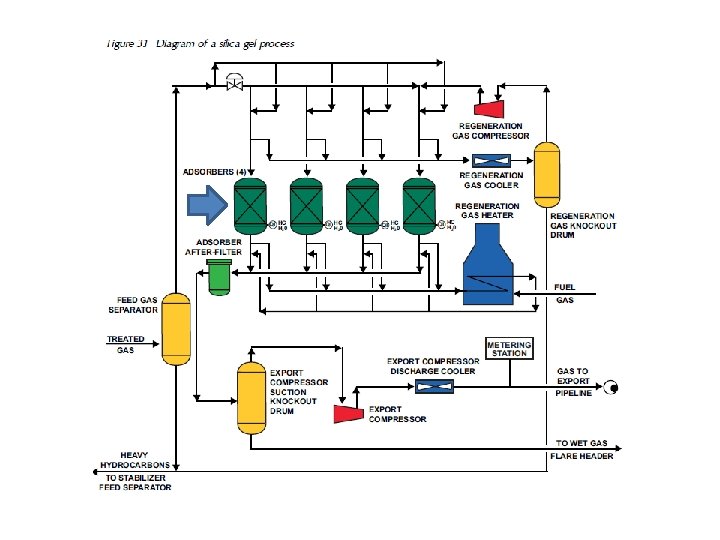
Water dew-point control • Also known as water removal or dehydration • Three common methods 1. Silica gel (Fig 3. 1) 2. Glycol (Fig 3. 2) 3. Molecular sieve (later chapter)
Water dew-point control • Silica gel (Fig 3. 1 & pg. 36 -37) • • • Water or hydrocarbon dew-point control. Passed through multiple beds of silica adsorbent Adsorption – the process used to remove water vapor from air or natural gas. (the adhesion in an extremely thin layer of molecules (as of gases, solutes, or liquids) to the surfaces of solid bodies or liquids with which they are in contact) 1. Liquid hydrocarbons (NGL) are recovered from natural gas by passing the gas through activated charcoal, silica gel, or other solids – which extract the heavier hydrocarbons. 2. Treatment of the solid removes the adsorbed hydrocarbons – which are collected and recondensed. 3. Knockout drum – a separator used to separate the gas and liquid (NGL or water). 4. “Lean” regeneration gas removes the hydrocarbons from the solid adsorbers.
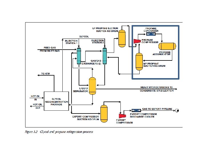
Water dew-point control • Glycol/Propane system (Fig 3. 2 & pg. 37 -38) • Glycol is used for water dew-point control • Refrigeration is used for hydrocarbon dewpoint control. • Liquid propane is used for the refrigerant. • Glycol is sprayed into the gas stream. • Glycol absorbs the water. • Types of glycol used MEG, DEG, TEG. • Glycol regenerated by heating to evaporate out moisture.
Hydrocarbon dew-point control • Also known as natural gas liquid (NGL) recovery • Natural gas liquid (NGL) are those hydrocarbon liquids that are liquefied at the surface in the field facilities or in gas processing plants. These liquids include propane, butane and natural gasoline. • Methods used for hydrocarbon dew-point control include: 1. Low-temperature separation (refrigeration) 2. Expander 3. Joule-Thomson (J-T)
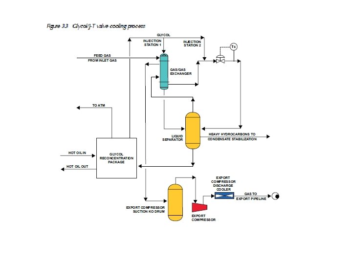
Water dew-point control • Glycol/J-T Valve Cooling Process(Fig 3. 3) • Glycol is used to control the water dewpoint • Joule-Thompson (J-T) valve system controls the hydrocarbon dew-point. • J-T valve – A detector cooling device in which a gas under high pressure escapes through and expansion valve in the tank; as the escaped valve liquefies (condenses) it cools the site of the sensor.
Water dew-point control • Glycol/J-T Valve Cooling Process(Fig 3. 3) • Joule-Thomson effect – the change in gas temperature that occurs when the gas is expanded at a constant internal energy from high to low pressure. The effect for most gases at normal pressure is a cooling of the gas. The exceptions are hydrogen and helium.
Refrigeration System • Operates through the continuous circulation of a refrigerant in a four-step cycle. 1. Expansion 2. Evaporation 3. Compression 4. Condensation • Operates much like a home air conditioner • Hot air blows across the evaporator causing the refrigerant to vaporize.
Refrigeration System • A gas processing plant refrigeration system uses a different refrigerant – liquid propane. • Fig. 3. 4 – Liquid propane flows from the gas surge tank to an oil chiller and the gas chiller. • The gas and oil chillers perform the function of an evaporator – causing the refrigerant (propaned) to vaporize. (The gas and oil are warmer) • Oil and gas flow through the tubes • Propane in the shell vaporizes • Propane vapor flows through the suction scrubber and on to the compressor. (removes liquids before goes to compressor)
Refrigeration System • The compressor raises the pressure of the propane vapor. • The propane will condense when cooled by cooling water and then is compressed – just as a refrigerant is compressed and condensed. • The propane returns to the surge tank as a liquid.
2 -stage Compression Condensation Evaporation Fig. 3. 4 Expansion
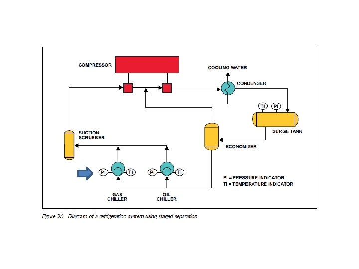
Economizers • Propane in the surge tank of the refrigeration system is similar in properties to the liquids coming from a high-pressure oil well • To increase the recovery of these liquids we want to minimize the evaporation of these liquids • At the oil well this process is called staged separation and serves to maximize the amount of recovered liquids • In the gas plant a similar system, called an economizer, serves to maximize the amount of liquid propane reaching the chiller (Fig 3. 6) • Cooled gas also used to reduce heating during gas compression
Chillers • Maximum refrigeration (or heating) occurs when tubes are completely covered by refrigerant (heating medium) • Level controller set to keep level just above tubes to allow adequate space for liquid/vapor separation to occur
Possible Operating Problems • Propane Quality – Excess ethane increases compressor discharge pressures – Excess butane increases the temperature in the chiller • and PI are used along with physical property graphs for propane/ethane or propane/butane mixtures to determine quality of the propane. TI
• Record T and P in the propane storage tank • Compare to graph • Stay below 2% ethane by venting gas • Record T and P in the chiller • Compare to graph • Drain excess butanes (liquid) from the tank (density)
Additional Problems • Air-cooled condensers must run efficiently and be properly maintained – Fans – Drivers – Drive assembly (bearings, gear reduction) • Cooling water condensers – Maintain circulation – Record temps • Refrigerant output temp • Cooling water output temp – When scaling occurs these two temps become farther apart (poor heat transfer) at the same refrigerant flow rate
Multi-stage refrigeration • Common to have two-, three- or four-stages in a refrigeration system • Note: cooling demand for condensing refrigerant into liquid at the surge tank goes up from two-stage to three stage – Air cooling for two stage – Cooling water for three stage – Propane cooling used for ethane system (note: the very low evaporation temperatures that can be achieved) • Power consumption varies with evaporation and refrigerant-cooling requirements
Two-stage Refrigeration
Three-stage refrigeration system