Register Transfer and Microoperations Contents Register Transfer language


")
 • To reduce number of wires, we construct a")
 • A bus system to multiplex K registers with")
 • What is three-state buffer? Or ( tri-state")
 • To construct common bus for K registers")
 • Example: Draw the diagram of a bus")


![Memory transfer • Write: M [AR] ← R 1 means: • transfers the content](https://slidetodoc.com/presentation_image_h2/cbb85457b312aa8fb5101c396013a71f/image-25.jpg "Memory transfer • Write: M [AR] ← R 1 means: • transfers the content")


- Slides: 52
Register Transfer and Micro-operations
Contents • Register Transfer language and Register Transfer. • Bus and Memory Transfers. • Arithmetic Micro-operations. • Logic Micro-operations. • Shift Micro-operations. • Arithmetic Logic Shift Unit.
Register Transfer language • Modules of a digital system are best defined by a set of registers and the operations that are performed on the binary information stored in them. • Micro-operation: Operation executed on data stored in registers. • Result of operations: may replace data in registers, or transfer it to another register. • Examples of Micro-operations: shift, count, clear and load.
Register Transfer language Organization of a digital system is best defined by: I. The set of registers in the system. 2. The operations that are performed on the data stored in the registers. 3. The control that supervises the sequence of operations in the system • register transfer operations: Information flow and processing performed on the data stored in the registers. • Register Transfer Language(RTL): The symbolic notation used to describe the micro-operation transfers among registers.
Register Transfer language Why Register transfer language? • symbolic language • convenient tool for describing the • internal organization of digital computers • Can also be used to facilitate the design • process of digital systems.
Register Transfer • Registers are designated by capital letters with numbers to denote the function of the register. • MAR : register that holds an address for the memory unit (memory address register). • R 1: processor register. • The most common representation for a register :
Register Transfer • Individual flip-flops in n-bit register are numbered in sequence from 0 to n-1. and is represented as: • Numbering of bits in 16 -bit register can be marked as:
Register Transfer • 16 -bit register can be partitioned into two parts: Bits 0 to 7 are assigned L (low byte) Bits 8 to 15 are assigned H (high byte) The name for the 16 -bit register is PC. PC(L) or PC(0 -7) refers to the low byte PC(H) or PC(8 -16) refers to the high byte
Register Transfer, Example 1 • Information transfer from one register to another is represented as: Means: transfer the content of register R 1 into register R 2. Note: R 2 content will be replaced by R 1 content will not change. • Normally transfer occur only under a control condition : • Where p, is a control signal. Control function :
Register Transfer, Example 1 • The previous statement implies the following hardware construction: Where n indicates any number of bits. R 2 has load input that is activated by the control input (p) Clock is not included as a variable in the register transfer statement, why?
Register Transfer, Example 1
Register Transfer, Example 2 Comma separates two or more operations executed at the same time. T: R 2 R 1 , R 1 R 2 An operation that exchanges the contents of the two registers during one common clock pulse provided T=1.
Basic symbols for register transfer
Bus and Memory Transfer • Bus is a path (of a group of wires) over which information is transferred, from any of several sources to any of several destinations. • From a register to bus: BUS R
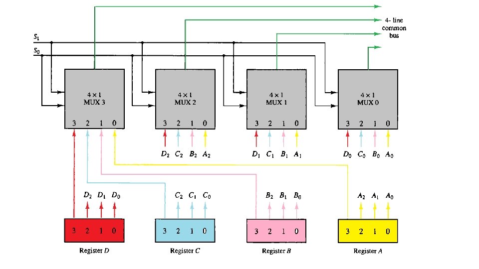
Common bus system (using multiplexers) • To reduce number of wires, we construct a Common bus system, one way is using Multiplexers Register A Bus lines Register B Register C Register D
Common bus system (using multiplexers) • A bus system to multiplex K registers with n bits each, needs: • n multiplexers. • Size of each multiplexer is Kx 1 • Example: The common bus for 4 register of 4 bits each needs 4 (4 x 1) multiplexers • Will need 2 selection lines:
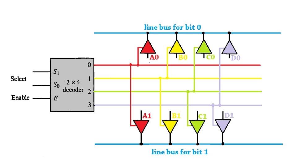
Common bus system (using three-state buffer) • What is three-state buffer? Or ( tri-state buffer) is logic circuit element that has three states: 0, 1 and high impedance (means the output is disconnected). • Has two inputs: a data input A and a control input C. • When C=1, the output is the input. • when C=0, the output disabled, gate goes to high impedance.
Common bus system (using three-state buffer) • To construct common bus for K registers of n bits, we need: • One Decoder (size depending on the number of registers). • n circuits with K buffers.
Common bus system (using three-state buffer) • Example: Draw the diagram of a bus system using tri-state buffers for 4 registers of 2 bits each. Solution: We will need: • One (2 x 4) decoder • 2 circuits (bus lines) with 4 buffers.
Practice • Draw the diagram of a bus system using tri-state buffers for 3 registers of 4 bits each
Simple RAM Design
Memory transfer • Read operation: The transfer of information from a memory word to the outside environment. • Write operation: The transfer of new information to be stored into the memory. • A memory word will be symbolized by the letter M. • It is necessary to specify the address of M when writing memory transfer operations, example M [address] • Read: DR ← M [AR] means: • data from the memory unit M which has the address AR, will be transferred to the data register DR.
Memory transfer • Write: M [AR] ← R 1 means: • transfers the content of the register R 1 to a memory word M selected by the address AR.
Arithmetic Micro Operations • Elementary operations performed with the data stored in registers. • Classified into four categories: 1. Register transfer micro-operations transfer binary information from one register to another. 2. Arithmetic micro-operations perform arithmetic operation on numeric data stored in registers. 3. Logic micro-operations perform bit manipulation operations on nonnumeric data stored in registers. 4. Shift micro-operations perform shift operations on data stored in registers.
Arithmetic Micro Operations • Basic arithmetic micro-operations: • • • Addition Subtraction Increment Decrement Shift • R 3 ← R 1 + R 2 • specifies an add micro-operation • It states that the contents of register R 1 are added to the contents of register R 2 and the sum transferred to register R 3.
Arithmetic Micro Operations • . • Subtraction: • R 2 is the symbol for the 1’s complement of R 2. Adding 1 to the 1’s complement produces the 2’s complement. Adding the contents of R 1 to the 2’s complement of R 2 is equivalent to R 1 – R 2.
Basic Set of Micro-operations
Binary Adder
Binary Adder-Subtractor
Binary Incrementer • The increment micro-operation adds one to a number in a register
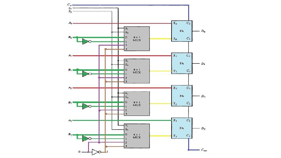
Arithmetic Circuit • The arithmetic micro-operations can be implemented in one composite arithmetic circuit. • The diagram of a 4 -bit arithmetic circuit contains: • • 4 full-adder circuits. 4 multiplexers for choosing different operations. 2 (4 -bit) inputs A and B. One (4 -bit) output D. • The output of the binary adder is calculated from the following arithmetic sum: D = A + Y + C in
Arithmetic Circuit Function Table
Logic Micro-operations • Logic micro operations specify binary operations for strings of bits stored in registers. • Each bit of the register is considered separately. • Example: P: R 1 ← R 1 ⊕ R 2 • Means exclusive-OR microoperation with the contents of two registers R 1 and R 2, when p=1. • if content of R 1=1010, the content of R 2 =1100, then:
Logic Micro-operations • Symbols: • Special symbols will be adopted for the logic micro-operations OR, AND, and complement, to distinguish them from the corresponding symbols used to express Boolean functions. Operation OR Boolean Function/ variables/control + Add AND Register Micro-operation ∨ +. ∧
Logic Micro-operations • Example: P + Q: R 1 ← R 2 + R 3, R 4 ← R 5 ∨ R 6 • The + between P and Q : OR operation (two binary variables) • The + between R 2 and R 3: Add micro-operation. • the symbol ∨ : OR micro-operation (between register R 5 and R 6).
Logic Micro-operations • The table shows Sixteen Logic Micro operations. • the Boolean functions listed in the first column represent a relationship between two binary variables x and y. • The logic micro-operations listed in the second column represent a relationship between the binary content of two registers A and B. (Each bit of the register is treated as a binary variable)
Hardware Implementation • Function table
Shift Micro-operations • Shift micro-operations are used for serial transfer of data. • The contents of a register can be shifted to the left or the right. • There are three type of shifts : • 1. Logical Shift • 2. Circular Shift • 3. Arithmetic Shift
Logical Shift • A logical shift is one that transfers 0 through the serial input. • Symbols: • R 1 shl R 1 (means: R 1 shifts left) • R 2 shr R 2 (means: R 1 shifts right) • Example: Use a Logical Left Shift Operation on the bit pattern 10011000.
Circular shift • The circular shift circulates the bits of the register around the two ends without loss of information. • This is accomplished by connecting serial output of the shift register to its serial input. • Symbols: • R 1 cil R 1 (means: circular shift left) • R 2 cir R 2 (means: circular shift right)
Circular shift • Example: Use a Circular Left Shift Operation on the bit pattern 10011000.
Arithmetic Shift • An arithmetic shift is a micro-operation that shifts a signed binary number to the left or right. • Arithmetic right shift divides the number by two. • Arithmetic left shift multiplies a signed binary number by two. • Arithmetic shifts must leave the sign bit unchanged because the sign of the number remains the same when it is multiplied or divided by two.
Arithmetic Shift • Example 1: Use an Arithmetic right shift operation on the bit pattern 1001. (The pattern is an integer in two’s complement format) • The leftmost bit is retained and also copied to its right neighbor bit. • The original number was − 103 and the new number is − 52, which is the result of dividing − 103 by 2 truncated to the smaller integer.
Arithmetic Shift • Example 2: • Use an Arithmetic left shift operation on the bit pattern 11011001. (The pattern is an integer in two’s complement format) • The leftmost bit is lost and a 0 is inserted as the rightmost bit. • The original number was − 39 and the new number is − 78. The original number is multiplied by two. The operation is valid because no underflow occurred.
Arithmetic Shift • Example 3: • Use an Arithmetic left shift operation on the bit pattern 01111111. The pattern is an integer in two’s complement format • The leftmost bit is lost and a 0 is inserted as the rightmost bit. • The original number was 127 and the new number is 0. Here the result is not valid because an overflow has occurred. The expected answer 127 x 2 = 254, so it cannot be represented by an 8 -bit sign pattern.
Hardware Implementation 4 -bit combinational circuit shifter
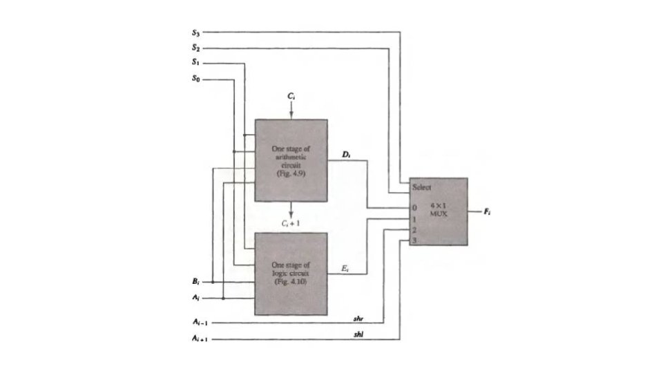
Arithmetic Logic Shift Unit