PTT 205RY 21 HEAT AND MASS TRANSFER Heat

")


 one fluid mixed")


 1")


 counterflow exchanger")
counterflow exchanger; b)parallel flow exchanger (Geankoplis, 4 th")

")
/2796 = 1. 607 Using Fig. 4(a) for")


- Slides: 41
PTT 205/RY 21 HEAT AND MASS TRANSFER Heat Exchangers By: Noor Amirah Abdul Halim
Topic Outline • • • Types of heat exchangers Log Mean Temperature Different (LMTD) Correction Factor of LMTD Heat Exchanger Effectiveness Fouling Factors
HEAT EXCHANGERS • Types of heat exchangers: 1. Double pipe heat exchanger 2. Shell and tube exchanger 3. Plate-type exchanger 4. Cross flow exchanger The function of a heat exchanger is to increase the temperature of a cooler fluid and decrease the temperature of a hotter fluid.
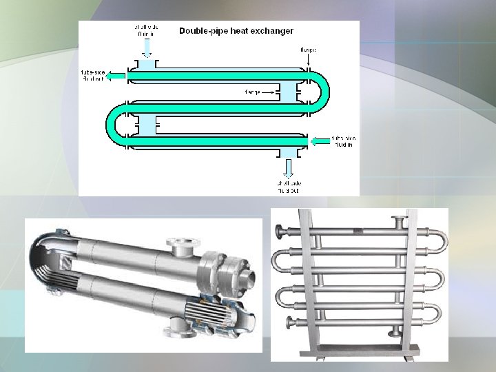
1. Double pipe heat exchanger • The simplest configuration • One fluid flow through the inside pipe, and the second fluid flows through the annular space between the outside and the inside pipe. • The fluid can be in co-current or countercurrent flow. • Useful for small flow rates and when not more than 100 – 150 ft 2 of surface is required. • Can withstand high pressure and be used easily (sections of tube can be increased or decreased as needed).
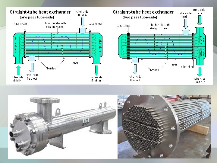
2. Shell and Tube Exchanger • The most important type of exchanger in use in oil refineries and larger chemical processes and is suited for higherpressure applications. • Useful for larger flow rates as compared to double pipe heat exchanger. • Consists of a shell (a large pressure vessel) with a bundle of tubes inside it. • One fluid runs through the tubes, and another fluid flows over the tubes (through the shell) to transfer heat between the two fluids.
1 -1 Shell and Tube Exchanger • The simplest configuration: 1 -1 counterflow exchanger (one shell pass and one tube pass) • The cold fluid enters and flow inside through all the tubes in parallel in one pass • The hot fluid enters at the other end and flow counterflow across the outside the tubes in the shell side. • Cross-baffles used to induce turbulence and increase the shell side heat transfer coefficient
1 -2 Shell and Tube Exchanger • • 1 shell pass and 2 tube passes (1 -2 exchanger)) The liquid on the tube side flows in two passes The shell-side liquid flows in one pass In the first pass of the tube side, the cold fluid is flowing counterflow to the hot shell-side fluid • In the second pass of the tube side, the cold fluid flows in parallel (co-current)
2 -4 Shell and Tube Exchanger
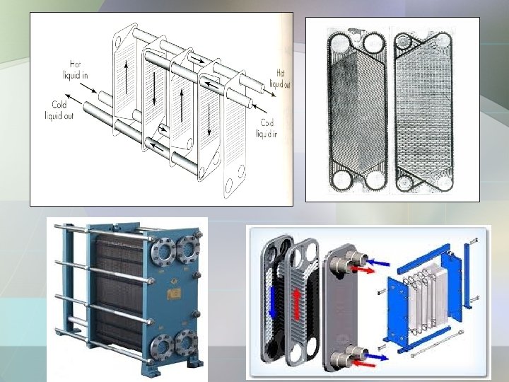
3. Plate heat exchanger • Use metal plates to transfer heat between two fluids • Consist of many corrugated stainless steel sheets separated by polymer gaskets and clamped in a steel frame. • The corrugation induce turbulence for improve heat transfer • The space between plates is equal to the depth of the corrugations (2 - 5 mm) • The plates are compressed in a rigid frame to create an arrangement of parallel flow channels with alternating hot and cold fluids. • Major advantage over a conventional heat exchanger in that the fluids are exposed to a much larger surface area because the fluids spread out over the plates.
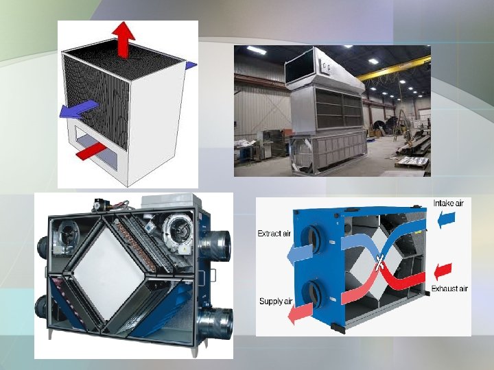
4. Cross-flow exchanger • Types of cross-flow heat exchangers : (a) one fluid mixed (gas) and one fluid unmixed; (b) both fluids unmixed. • A common device used to heat or cool a gas such as air • One of the fluids, which is a liquid, flows inside through the tubes, and the exterior gas flows across the tube bundle by forced or sometimes natural convection.
• The fluid inside the tubes is considered to be unmixed, since it is confined and cannot mix with any other stream. • The gas flow outside the tubes is mixed, since it can move about freely between the tubes, and there will be a tendency for the gas temperature to equalize in the direction normal to the flow. • For the unmixed fluid inside the tubes, there will be a temperature gradient both parallel and normal to the direction of flow.
• This type is typically used in air- conditioning and space-heating applications. • In this type the gas flows across a finned-tube bundle and is unmixed, since it is confined in separate flow channels between the fins as it passes over the tubes. The fluid in the tubes is unmixed.
General Heat Balance and Heat Transfer Rate
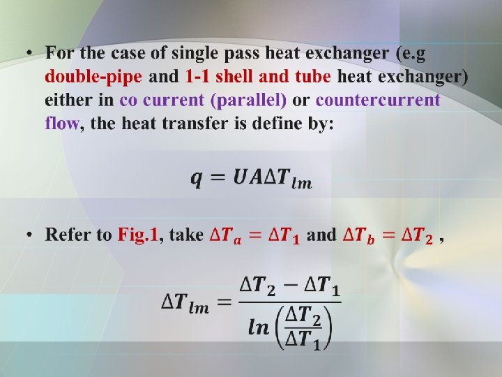
Log Mean Temperature Difference •
Fig 1. Temperature profiles for single pass heat exchangers (double pipe/1 -1 shell and tube heat exchangers)
EXERCISE A heavy hydrocarbon oil which has a cpm = 2. 30 k. J/kg. K is being cooled in heat exchanger from 371. 9 K to 349. 7 K and flows inside the tube at a rate of 3630 kg/h. A flow of 1450 kg water/h enters at 288. 6 K for cooling and flows outside the tube. ( For water, take cpm = 4. 187 k. J/kg. K is) a) For counterflow, calculate the (i) Outlet water temperature (ii) Heat transfer area if the overall heat transfer coefficient equal to 340 W/m 2. K. b) Repeat for cocurrent flow
Log Mean Temperature Difference Correction Factors • In cases where a multiple- pass heat exchanger (e. g 1 -2 /1 -4/ 2 -4 shell and tube heat exchanger) is involved, it is necessary to obtain a different expression for the mean temperature differences, depending on the arrangement of the shell and tube passes. Thus, a correction factor, FT is needed. • The relationship between LMTD and FT is define as below: Where is define as the correct mean temperature drop. • The general equation for heat transfer across surface of an exchanger is:
• Figure 2& 3 shows the correction factor to LMTD for: a) 1 -2 and 1 -4 exchangers b) 2 -4 exchangers • The figures were defined by two dimensionless ratios as follows: • Based on the above ratios, LMTD can be written as:
Fig. 2 Correction factor to LMTD for 1 -2 and 1 -4 exchangers (Geankoplis, 4 th ed. )
Fig. 3 Correction factor to LMTD for 2 -4 exchangers (Geankoplis, 4 th ed. )
EXAMPLE 1 A 1 -2 heat exchanger containing one shell pass and two tube passes heats 2. 52 kg/s of water from 21. 1 to 54. 4 0 C by using hot water under pressure entering at 115. 6 and leaving at 48. 9 0 C. The outside surface area of the tubes in the exchanger is Ao = 9. 30 m 2. a) Calculate the mean temperature different ΔTm in the exchanger and the overall heat transfer coefficient Uo. b) For the same temperatures but using a 2 -4 exchanger, what would be the ΔTm? Solution: The temperatures are as follows: Thi = 115. 6 0 C Tho = 48. 9 0 C Tci = 21. 2 0 C Tco = 54. 4 0 C
Heat balance on the cold water, assume Cpm of water of 4187 J/kg. K Tco – Tci = (54. 4 – 21. 1) 0 C = 33. 3 K q = m. Cpm(Tco – Tci) = (2. 52)(4187)(54. 4 – 21. 1) = 348 200 W The log mean temperature difference Calculate the Z and Y values to find FT value
From Fig. 2 , FT = 0. 74 Thus, the mean temperature difference is: Rearranging the heat transfer equation to solve for Uo and substituting the known values, we have b) for 2 -4 exchanger, refer to Fig. 3 , FT = 0. 94, Then, Hence, in this case the 2 -4 exchanger utilizes more of the available temperature driving force.
Heat Exchanger Effectiveness – NTU Method • The LMTD is used in equation if the inlet and outlet temperatures of the two fluids are known and can be determined by a heat balance. • The surface area can be determined if U is known. • However, when the temperature of the fluids leaving the exchanger are not known, the trial-and-error procedure is necessary. • To solve these cases, a method called the heat exchanger effectiveness is used which does not involve any of the outlet temperatures. • The Effectiveness – NTU (Number of Transfer Unit) method is a procedure for evaluating the performance of heat exchangers if heat transfer area, A and construction details are known.
• For this cases, the heat transfer rate can be expressed by: Note that this equation uses only inlet temperatures. • Cmin is refer to Cc or CH which have the minimum heat capacity obtained from hot and cold stream • ɛ is the heat exchanger effectiveness coefficient which can be evaluated using equations or NTU correlations.
• Equation for counterflow, • Equation for parallel flow, • These equations have been plotted in convenient graphical form in Figure 4(a) and (b)
• Figure 4 shows the heat exchanger effectiveness, ε for a) counterflow exchanger b) parallel flow exchanger • From the figures, the effectiveness, ε is defined by the correlations of: Number of transfer units (NTU), And heat capacity ratio,
Figure 4 Heat exchanger effectiveness, ε: a)counterflow exchanger; b)parallel flow exchanger (Geankoplis, 4 th ed. )
EXAMPLE 2 Water flowing at a rate of 0. 667 kg/s enters a countercurrent heat exchanger at 308 K and is heated by an oil stream entering at 383 K at a rate of 2. 85 kg/s (cp = 1. 89 k. J/kg. K). The overall U = 300 W/m 2. K and the area A = 15. 0 m 2. Calculate the heat transfer rate and the exit water temperature. Solution Assuming that the exit water temperature is about 370 K, the cp for water at an average temperature of (308 + 370)/2 = 339 K is 4. 192 k. J/kg. K (refer Appendix). Then (mcp)H = CH = 2. 85(1. 89 x 103) = 5387 W/K and (mcp)C = CC = 0. 667(4. 192 x 103) = 2796 W/K = Cmin. Since CC is the minimum, Cmin /Cmax = 2796 / 5387 = 0. 519.
Appendix- Heat capacity of water (1 atm)
NTU = UA/Cmin = 300 (15. 0)/2796 = 1. 607 Using Fig. 4(a) for a counterflow exchanger, ε = 0. 71. Substituting into equation: q = ε Cmin (THi – TCi) = 0. 71 (2796)(383 – 308) = 148 900 W q = 148 900 = 2796 (TCo – 308) Solving TCo = 361. 3 K
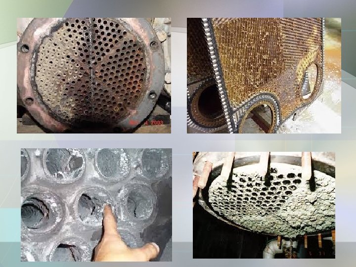
Fouling Factors in Heat Exchangers • One of the most common operational challenges encountered with heat exchangers is fouling. • Fouling is the buildup of sediments and debris on the surface area of a heat exchanger that inhibits heat transfer. • Fouling will reduce heat transfer, impede fluid flow, and increase the pressure drop across the heat exchanger. These deposits offer additional resistance to the flow of heat and reduce the overall heat transfer coefficient, U • As with many operational concerns, proper planning at the design stage can minimize the effects of fouling down the road. • Designers normally maximize the lifespan, runtime and efficiency of a heat exchanger by accounting for the amount of fouling an exchanger will sustain over a period of time. This often results in increasing the surface area of a heat exchanger, so that fouling will not have as much of an effect. • In many applications, such as refineries, heat exchangers will have to perform for several years without a cleaning. This means that the heat exchanger must be able to function efficiently for long periods of time. • Compensating for fouling by enlarging surface area allows heat exchangers to function with years of fouling.
There are several types of fouling, each forming depending on the type of fluid and conditions. The following are some of the more common fouling factors • Crystallization- one of the most common type of fouling. Certain salts commonly present in natural waters have a lower solubility in warm water than cold. Therefore, when cooling water is heated during the cooling process these dissolved salts will crystallize on the surface in the form of scale. - Common Solution: reducing the temperature of the heat transfer surface to softens the deposits • Sedimentation - the depositing of dirt, sand, rust, and other small matter is also common when fresh water is used. This can be controlled to a degree by the heat exchanger design. -Common Solution: velocity control • Biological Organic growth –algae growth or material occurs from chemical/ biological reactions, and can cause considerable damage when built up. -Common Solution: material selection
• Chemical Reaction Coking - appears where hydrocarbon deposits in a high temperature application. -Common Solution: reducing the temperature between the fluid and the heat transfer surface] • Corrosion - destroy surface areas of the heat exchangers, creating costly damage. Fouling will slow down heat transfer and damage equipment unless it is dealt with accordingly. -Common Solution: material selection • Freezing Fouling - results from overcooling at the heat transfer surface causing solidification of some of the fluid stream components. -Common Solution: reducing the temperature gradient between the fluid and the heat transfer surface. ]
THANK YOU