Plastics Product Design Design of Radii Surfaces of


- Slides: 24
Plastics Product Design
Design of Radii Surfaces of all intersections should be rounded. Large radii should be positioned at a junction of two or more surfaces to insure proper material flow and relieve any possibility of stress concentration. Any sharp corner that is subjected to loading and twisting will tend to be weak and break. All of the stressing within the part will be at the sharp corner. Corner radii should be a minimum of 1/4 of the part thickness. Flow of a material at a corner presents no problem if the corner is rounded. If the corner is square, the plastic material lodges in the corner and impedes even flow, thus causing flow marks and non-uniformity
Design of Fillets are used at the base of ribs or bosses to facilitate the flow of plastic material and to eliminate sharp corners, thus reducing stress concentrations in the molded part. All plastic parts requiring bosses should be provided with fillets at the junction of the boss with the main body of the plastic part. Radii of these fillets should be at least 0. 010 in. and preferably 0. 030 in. The addition of a fillet increases the strength of the mold and the molded part. Fillets should be placed at the junction of bosses and ribs with the main body of the part. Curves and fillets molded in a part prevent stress concentrations, and strength, and help eliminate warpage.
Fillets generally reduce the cost of the mold, the molded part is more streamlined, and the corners of the molded part are easier to keep clean of dust. A well-designed part that has adequate curves and fillets to prevent stress concentrations and warpage.
Design of Ribs and Bosses may be defined as protruding studs on a part that assist in the assembling of the plastic part with another piece. Because they are frequently the anchoring member between the plastic part and mating part, they are subject to strains and stresses not found in other areas of the part. Avoid bosses that merge into sidewalls because they can form thick sections that lead to sink. Instead, position the bosses away from the sidewall, and if needed, use connecting ribs for support. Normally, the boss hole should extend to the base-wall level, even if the full depth is not needed for assembly.
Ribs may be defined as long protrusions on the part, which may be used to decorate to strengthen the part or, if properly placed, to help prevent it form warping. Ribs provide a means to economically augment stiffness and strength in molded parts without increasing overall wall thickness. Other uses for ribs include: • Locating and captivating components of an assembly; • Providing alignment in mating parts; and • Acting as stops or guides for mechanisms Proper rib design involves five main issues: thickness, height, location, quantity, and moldability. Thick ribs often cause sink and cosmetic problems on the opposite surface of the wall to which they are attached.
Rib thickness also determines the cooling rate and degree of shrinkage in ribs, which in turn affects overall part warpage. A rib should be located in the corner or side of a molded part.
Design for Flow and shape In molding with any plastic material, parts should be designed with ample curves, except at the parting lines of the mold cavity section. If the material, as it is being molded, does not sweep across the confined areas of the mold, gas pockets or voids may develop. POOR DESIGN W – WEAK WELD LINES LOUVERS OPENINGS NOT WELL SPACED HORIZONTAL BETTER DESIGN OPENINGS ARE WELL SPACED
The strength of a plastic part depends largely on good design. When plastic materials flow around protruding sections of a mold, they knit or weld on the other side. The thermoplastic materials tend to cool as they fill the mold cavity, with the result that the weld or knit line will be weaker than the adjoining material Long louvers or open slots should be molded in the bottom of the mold so as to avoid welding as much as possible. If louvers or slots have to be made by the side of the mold, they should run up and down the face.
Moulded Holes are provided to allow assembly with other parts, to decorate the part and give it more eye appeal, or are functional, such as ventilators or louvers. Holes or openings can be round, square, rectangular, elliptical etc. Molded holes may be classified as blind, through, step, recess step, and intersecting. Core pins that protrude into the mold cavity make the holes when the part is molded. Through holes in the molded parts are easier to produce than blind holes, which do not go all the way through a part. Blind holes are made by core pins supported on one end only. The pins can be deflected and pushed off center by the pressures of the molten plastic material during the molding process. A good rule of thumb: the depth of the blind hole should be about twice the diameter of core pins up to 3/16", and up to four times the diameter of core pins over 3/16".
Holes parallel to draw A hole parallel to the draw is a hole whose axis is parallel to the movement of the mold as it opens and closes. Holes may also be molded at right angles to the draw and at oblique angles. Oblique angle holes should be avoided if possible, because it is very difficult and expensive to make a mold to operate at oblique angles, as they require split dies and retractable core pins. Moulded hole is the hole is made by a pin that is inserted into the mold. The pin is subject to breakage and wear. Holes may extend part way through the molded piece, in which case the steel pin making the hole is supported only at one end. Holes may extend entirely through the piece, in which case the pin may or may not be supported at both ends. The strength of the pin making the hole is influenced by the ratio of its mean diameter to its length called its "slenderness ratio.
Nearness of Holes to Each other and Side wall Because both thermoplastic and thermosetting plastics flow and knit inside the mold, strains are set up within the part. The flow of the compound around a pin making a hole and the welding of that compound on the other side of the pin are causes for strain lines. Strains should be spread over as wide an area as possible so as to minimize their effect. Non-uniform wall thickness cause in-equalities in curing time, but the part will be more susceptible to warping at very thin wall thickness when these sections are joined to much thicker wall sections.
If holes are molded, knit lines will occur on the opposite side of the holes from the gate and between the hole and the side wall. The distance between the hole and the side wall should be at least 1/8 in. , if maximum mechanical strength is required. The material between the wall of a hole and exterior wall of a part should be at least the thickness of the hole diameter. It will be noted that the wall thickness is uniform throughout, and there are no sharp corners for stress concentrations to develop.
Molding Holes Not Parallel To The Draw The axis of a hole is not parallel to the draw, either the pin making the hole must be removed from the part before the part is extracted from the mold or the pin must be removed with the part as it is extracted and then taken from the part. Usually, molded holes not parallel to the draw require more complicated molds or more direct molding labor than do the parallel to the draw, and thus, higher mold and parts costs results. Therefore, holes entering the side of the part should be avoided if possible. Extending side openings to the top of the part will lower costs.
Molded-in side holes are trouble-some to produce, because extra provision is required to actuate the core pins from the side. Side holes may be molded automatically by using the cam action in the mold or with hydraulic or pneumatic actuators. In compression molding, drilling after the part is molded is usually simpler.
Drilled and Tapped holes When holes parallel to the draw are too slender to be molded, it becomes necessary to drill these holes after the part has been molded. At times, it may be more economical to drill a side hole than to mold that hole. Good design calls for the spot location of a hole to be drilled. This spot acts as a guide for the drill entering the plastic. Spots should be made only for holes that are to be drilled parallel to the draw. A spot for a hole to be drilled perpendicular to draw should not be used. Drilled holes should be so designed that the drill enters the part perpendicularly. If through holes are drilled in the molded plastic part it is good practice to note on the drawing that the hole may be chip on the edge where the drill exits. It is best to avoid designing parts so that drilling must be done on an angled surface.
Many molded plastic parts have holes drilled in the part after molding. It is generally less expensive to build a drill jig to drill holes in a molded part than it is to incorporate elaborate retractable core pins in the die.
Molded holes are tapped. Holes to be tapped after molding or holes for selftapping screws or drive screws should be countersunk to allow the tap or screw to find its way in and to prevent chipping at the entering end. Holes to be tapped or used self-tapping screws should be countersunk. If a conical-head screw is not to extend above the surface of the plastic part, the hole for the screw should be designed with a 1/64 in. of vertical depth to allow for the variations in screws.
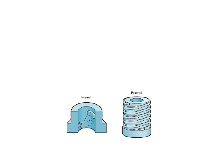
Moulded Threads The molding process accommodates thread forming directly in a part, avoiding the expense of secondary, thread-cutting steps. The cost and complexity of the tooling usually determines the feasibility of molding threads. Easily molded in both mold halves, external threads centered on the mold parting line add little to the molding cost. Typically, threads that do not lie on the parting line require slides or side actions that could add to molding costs. All threads molded in two halves are prone to parting line flash or mismatch. Thread designs requiring unscrewing devices add the most cost to the mold. Most of the mechanisms for molding internal threads — such as collapsible and unscrewing cores — significantly increase the mold’s cost and complexity.
Consider the following when specifying moulded-in threads: • Use the maximum allowable radius at the thread’s crest and root, • Stop threads short of the end to avoid making thin, feathered threads that can easily cross-thread , • Limit thread pitch to no more than 32 threads per inch for ease of molding and protection from cross threading and • Avoid tapered threads unless you can provide a positive stop that limits hoop stresses to safe limits for the material. Molded threads, particularly internal ones, should be designed so that they can be removed quickly from the mold. Most of the plastics compounds will shrink in the mold. Internal threads are made by a threaded pin in the mold, and the threads will shrink quickly around the pin. It is advisable to design molded threads no finer than 32 threads per inch and no longer than 1/2 in. , or tool much time will be taken by the press operator when unscrewing the part from the mold.
Moulded Lettering are used on plastic parts for identification. Raised letters are often less costly than depressed letters, because the raised letters are molded from letters recessed in the mold cavity, while depressed letters require the mold steel to be cut all around them. A raised letter is visible if it is only 0. 003 inch high. Letters normally 164 inch high are easily read, because they catch sharp highlights. Letters that are over 0. 030 inch high should be tapered and have fillets at the base. Raised letters can be decorated or painted by roll coating.
Surface Treatment The decorating of any plastic part is a surface treatment, and the first prerequisite is that the surface be clean and prepared in the right manner for decorating. Some of the common causes of failure in decorating plastic parts are: mold lubricants; dust; natural skin greasiness; excess surface plastizers; surface moisture and humidity conditions; and strains locked into the molded part. Molding-surface treatments can produce a variety of surface finishes and textures in the molded part. Textures can enhance the overall part aesthetics and hide surface blemishes such as minor sink and gate blush. Surface finishes range from high-gloss to heavy-matte. Photo etching the mold steel can impart special surface textures for parts.
END