PIMode Structure PIMS Rolf Wegner 29 10 2007


- Slides: 40
PI-Mode Structure (PIMS) Rolf Wegner 29. 10. 2007 PIMS Rolf Wegner 1
Outline • general overview • • • 29. 10. 2007 coupling tuning and end cells 7 cell cold model wave guide coupler transients summary and next steps PIMS Rolf Wegner 2
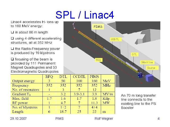
SPL / Linac 4 29. 10. 2007 PIMS Rolf Wegner 3
SPL / Linac 4 29. 10. 2007 PIMS Rolf Wegner 4
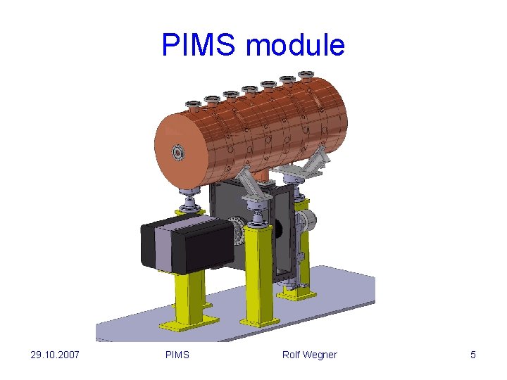
PIMS module 29. 10. 2007 PIMS Rolf Wegner 5
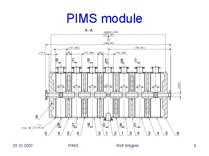
PIMS module 29. 10. 2007 PIMS Rolf Wegner 6
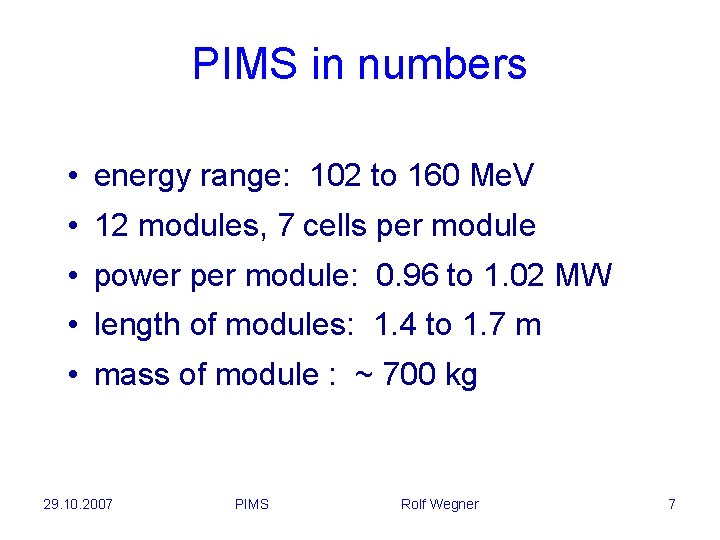
PIMS in numbers • energy range: 102 to 160 Me. V • 12 modules, 7 cells per module • power per module: 0. 96 to 1. 02 MW • length of modules: 1. 4 to 1. 7 m • mass of module : ~ 700 kg 29. 10. 2007 PIMS Rolf Wegner 7
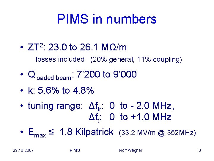
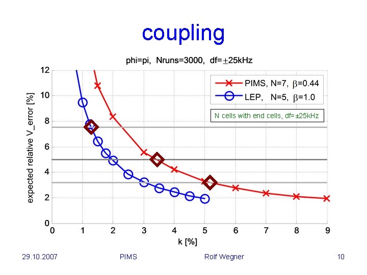
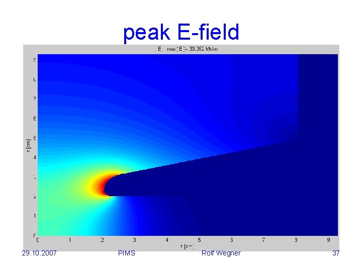
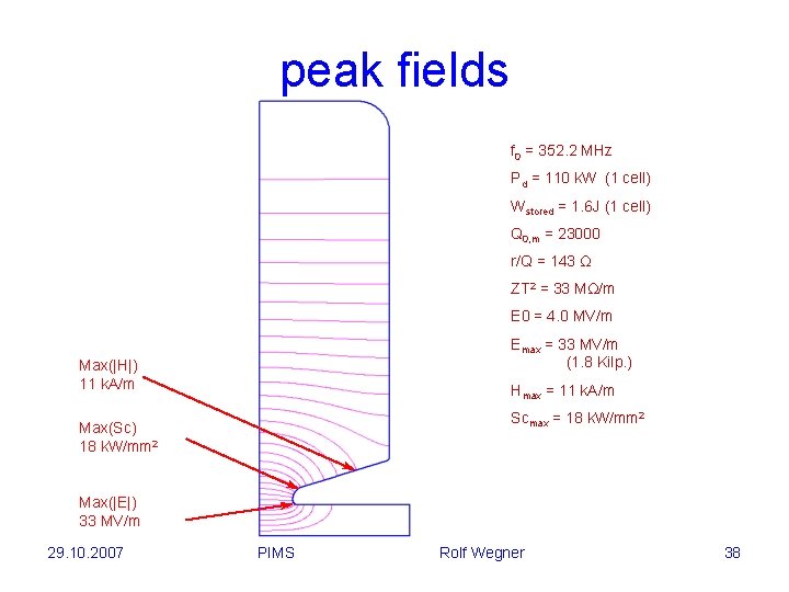
PIMS in numbers • ZT 2: 23. 0 to 26. 1 MΩ/m losses included (20% general, 11% coupling) • Qloaded, beam: 7’ 200 to 9’ 000 • k: 5. 6% to 4. 8% • tuning range: Δftr: 0 to - 2. 0 MHz, Δft: 0 to +1. 0 MHz • Emax ≤ 1. 8 Kilpatrick 29. 10. 2007 PIMS (33. 2 MV/m @ 352 MHz) Rolf Wegner 8
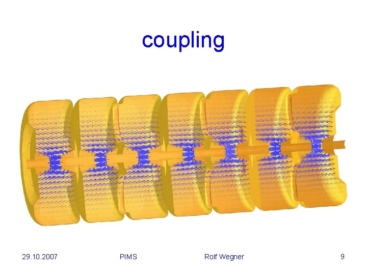
coupling 29. 10. 2007 PIMS Rolf Wegner 9
coupling N cells with end cells, df=± 25 k. Hz 29. 10. 2007 PIMS Rolf Wegner 10
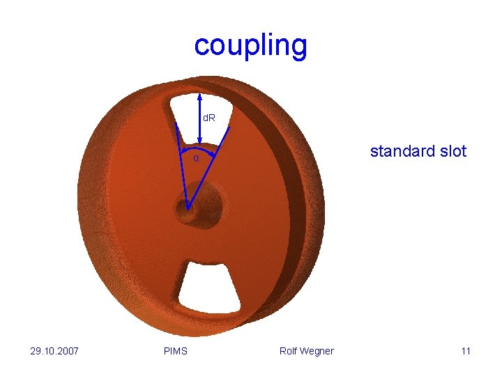
coupling d. R standard slot α 29. 10. 2007 PIMS Rolf Wegner 11
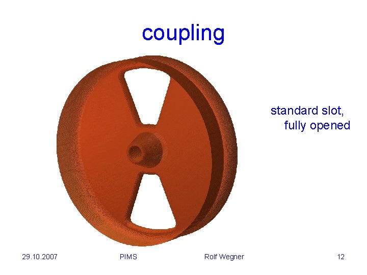
coupling standard slot, fully opened 29. 10. 2007 PIMS Rolf Wegner 12
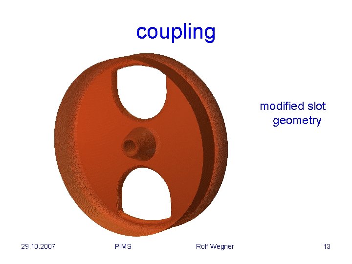
coupling modified slot geometry 29. 10. 2007 PIMS Rolf Wegner 13
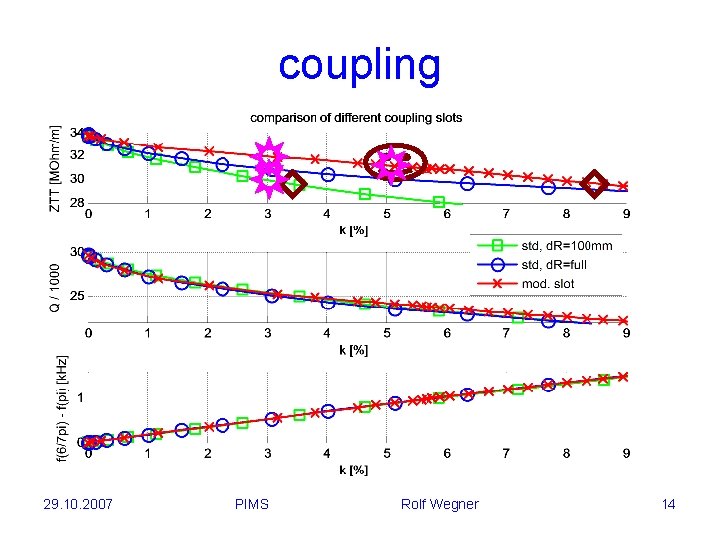
coupling 29. 10. 2007 PIMS Rolf Wegner 14
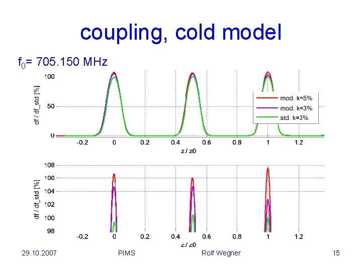
coupling, cold model f 0= 705. 150 MHz 29. 10. 2007 PIMS Rolf Wegner 15
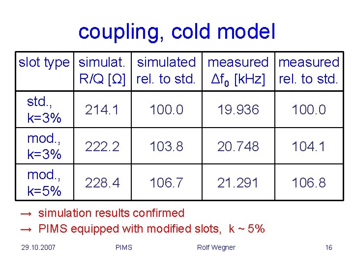
coupling, cold model slot type simulated measured R/Q [Ω] rel. to std. Δf 0 [k. Hz] rel. to std. , k=3% mod. , k=5% 214. 1 100. 0 19. 936 100. 0 222. 2 103. 8 20. 748 104. 1 228. 4 106. 7 21. 291 106. 8 → simulation results confirmed → PIMS equipped with modified slots, k ~ 5% 29. 10. 2007 PIMS Rolf Wegner 16
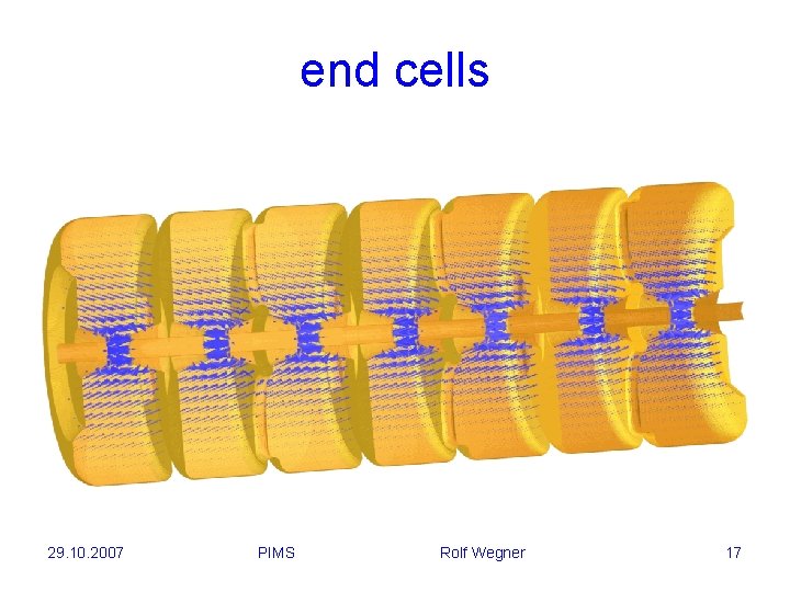
end cells 29. 10. 2007 PIMS Rolf Wegner 17
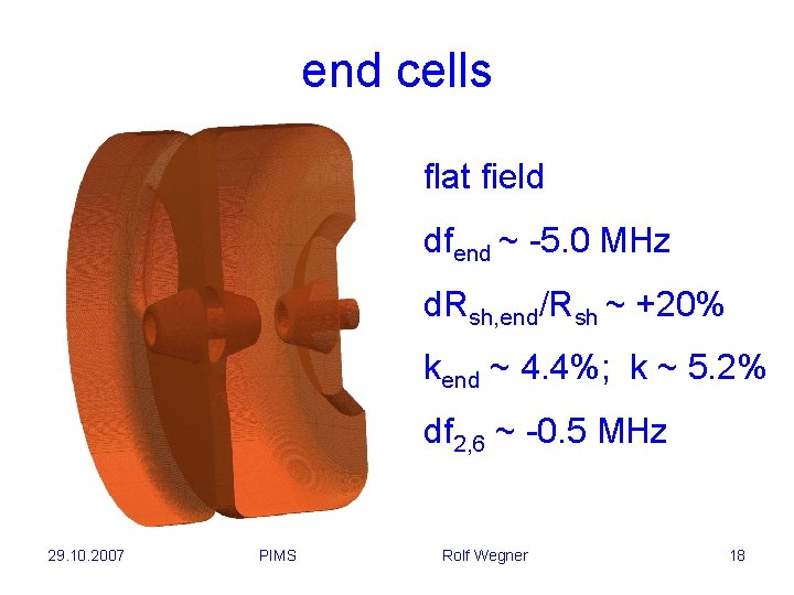
end cells flat field dfend ~ -5. 0 MHz d. Rsh, end/Rsh ~ +20% kend ~ 4. 4%; k ~ 5. 2% df 2, 6 ~ -0. 5 MHz 29. 10. 2007 PIMS Rolf Wegner 18
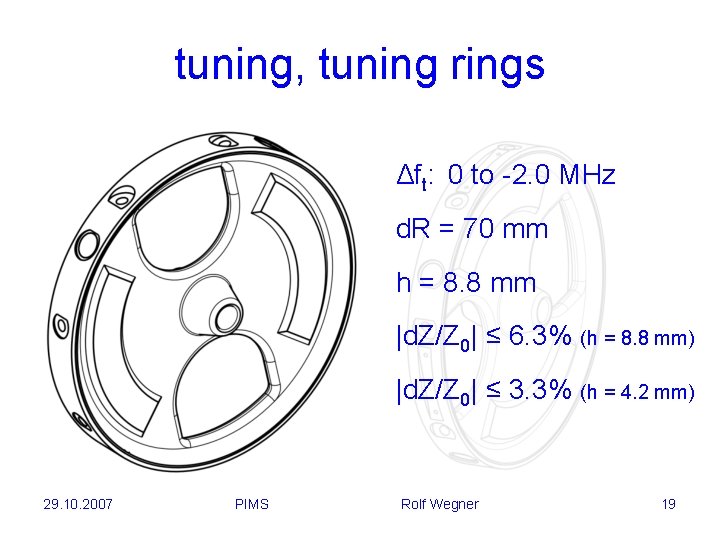
tuning, tuning rings Δft: 0 to -2. 0 MHz d. R = 70 mm h = 8. 8 mm |d. Z/Z 0| ≤ 6. 3% (h = 8. 8 mm) |d. Z/Z 0| ≤ 3. 3% (h = 4. 2 mm) 29. 10. 2007 PIMS Rolf Wegner 19
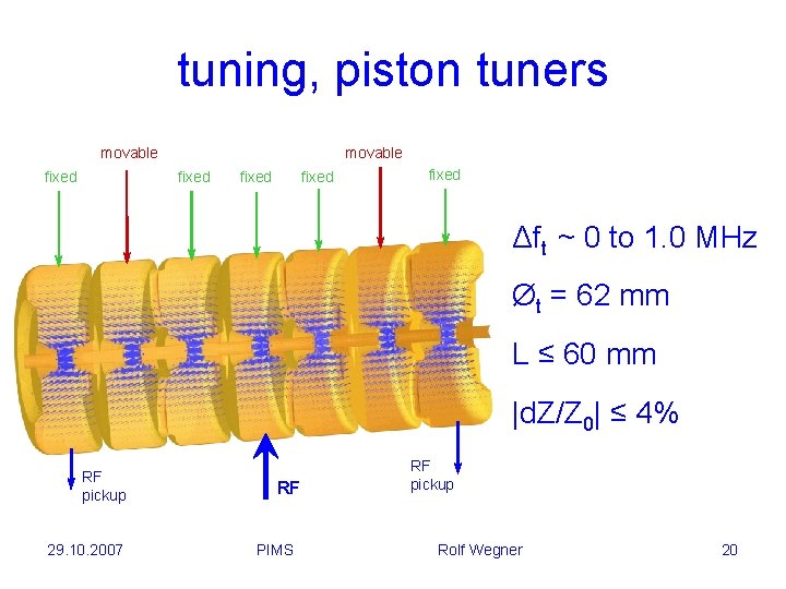
tuning, piston tuners movable fixed fixed Δft ~ 0 to 1. 0 MHz Øt = 62 mm L ≤ 60 mm |d. Z/Z 0| ≤ 4% RF pickup 29. 10. 2007 RF PIMS RF pickup Rolf Wegner 20
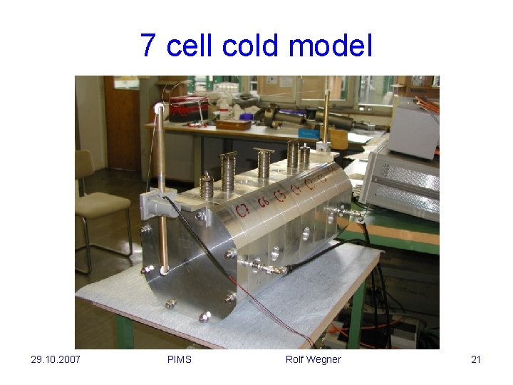
7 cell cold model 29. 10. 2007 PIMS Rolf Wegner 21
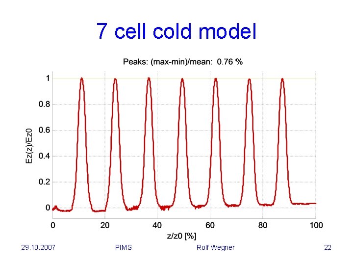
7 cell cold model 29. 10. 2007 PIMS Rolf Wegner 22
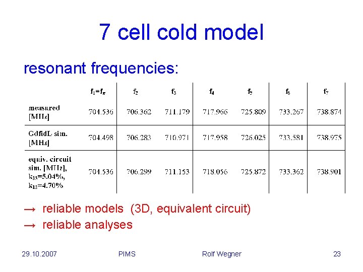
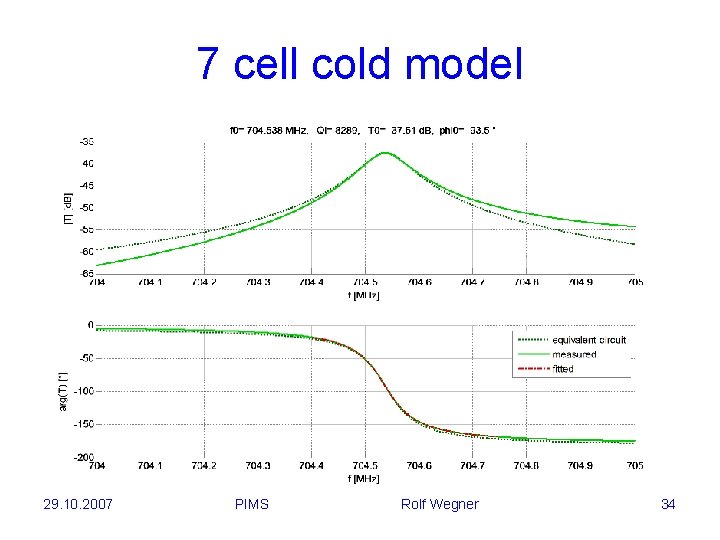
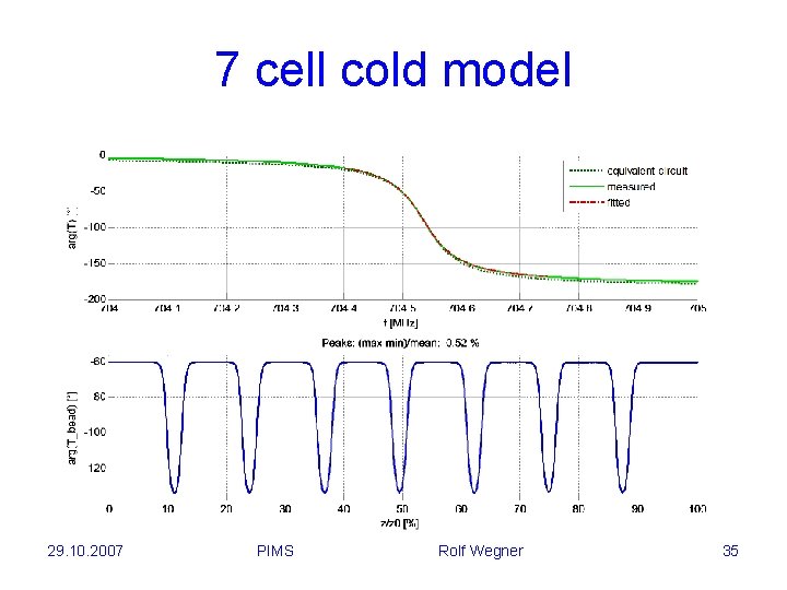
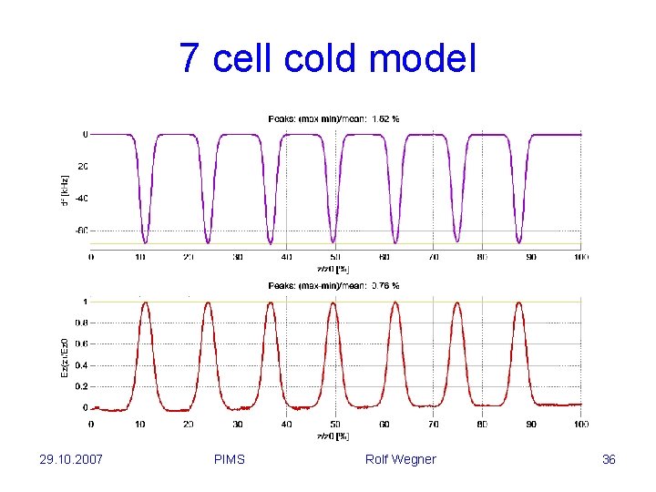
7 cell cold model resonant frequencies: → reliable models (3 D, equivalent circuit) → reliable analyses 29. 10. 2007 PIMS Rolf Wegner 23
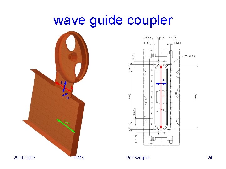
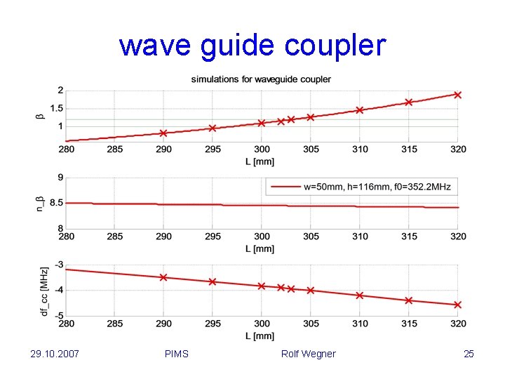
wave guide coupler w h L L w Lsc 29. 10. 2007 PIMS Rolf Wegner 24
wave guide coupler 29. 10. 2007 PIMS Rolf Wegner 25
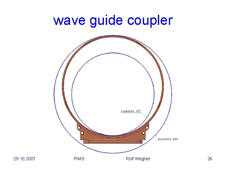
wave guide coupler 29. 10. 2007 PIMS Rolf Wegner 26
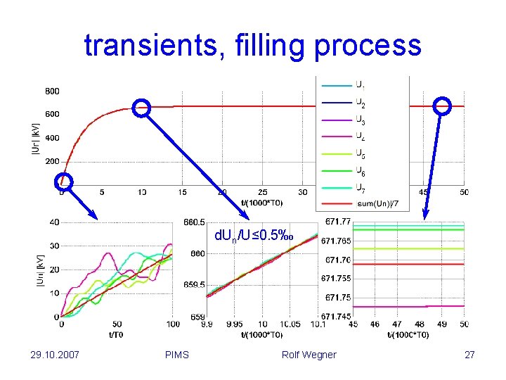
transients, filling process d. Un/U≤ 0. 5‰ 29. 10. 2007 PIMS Rolf Wegner 27
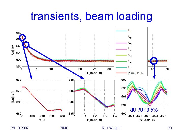
transients, beam loading d. Un/U≤ 0. 5% 29. 10. 2007 PIMS Rolf Wegner 28
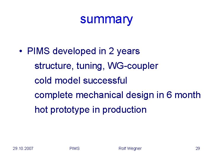
summary • PIMS developed in 2 years structure, tuning, WG-coupler cold model successful complete mechanical design in 6 month hot prototype in production 29. 10. 2007 PIMS Rolf Wegner 29
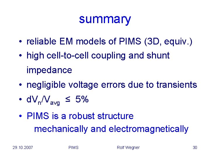
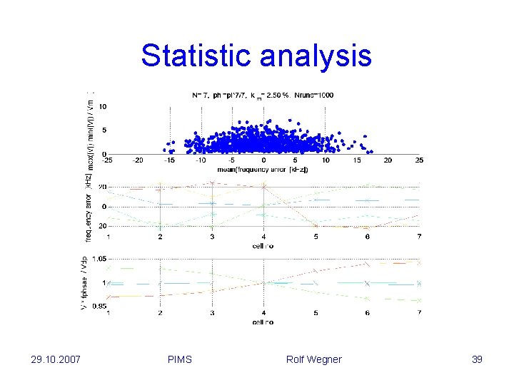
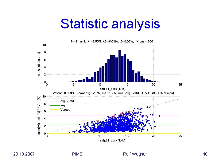
summary • reliable EM models of PIMS (3 D, equiv. ) • high cell-to-cell coupling and shunt impedance • negligible voltage errors due to transients • d. Vn/Vavg ≤ 5% • PIMS is a robust structure mechanically and electromagnetically 29. 10. 2007 PIMS Rolf Wegner 30
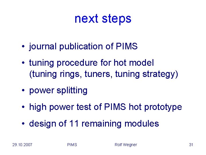
next steps • journal publication of PIMS • tuning procedure for hot model (tuning rings, tuners, tuning strategy) • power splitting • high power test of PIMS hot prototype • design of 11 remaining modules 29. 10. 2007 PIMS Rolf Wegner 31
29. 10. 2007 PIMS Rolf Wegner 32
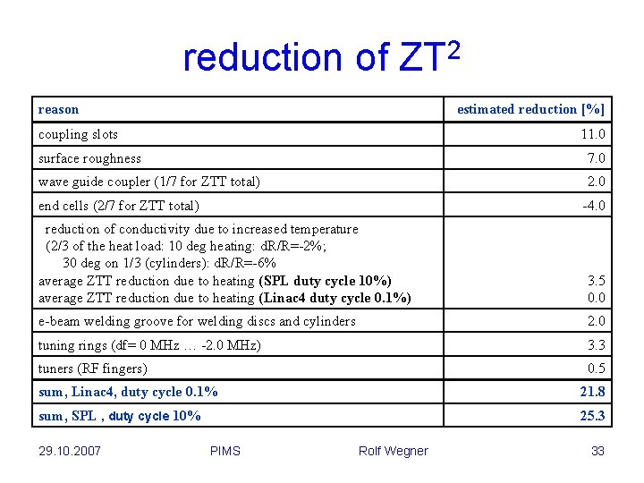
reduction of ZT 2 reason estimated reduction [%] coupling slots 11. 0 surface roughness 7. 0 wave guide coupler (1/7 for ZTT total) 2. 0 end cells (2/7 for ZTT total) -4. 0 reduction of conductivity due to increased temperature (2/3 of the heat load: 10 deg heating: d. R/R=-2%; 30 deg on 1/3 (cylinders): d. R/R=-6% average ZTT reduction due to heating (SPL duty cycle 10%) average ZTT reduction due to heating (Linac 4 duty cycle 0. 1%) 3. 5 0. 0 e-beam welding groove for welding discs and cylinders 2. 0 tuning rings (df= 0 MHz … -2. 0 MHz) 3. 3 tuners (RF fingers) 0. 5 sum, Linac 4, duty cycle 0. 1% 21. 8 sum, SPL , duty cycle 10% 25. 3 29. 10. 2007 PIMS Rolf Wegner 33
7 cell cold model 29. 10. 2007 PIMS Rolf Wegner 34
7 cell cold model 29. 10. 2007 PIMS Rolf Wegner 35
7 cell cold model 29. 10. 2007 PIMS Rolf Wegner 36
peak E-field 29. 10. 2007 PIMS Rolf Wegner 37
peak fields f 0 = 352. 2 MHz Pd = 110 k. W (1 cell) Wstored = 1. 6 J (1 cell) Q 0, m = 23000 r/Q = 143 Ω ZT 2 = 33 MΩ/m E 0 = 4. 0 MV/m Emax = 33 MV/m (1. 8 Kilp. ) Max(|H|) 11 k. A/m Hmax = 11 k. A/m Scmax = 18 k. W/mm 2 Max(Sc) 18 k. W/mm 2 Max(|E|) 33 MV/m 29. 10. 2007 PIMS Rolf Wegner 38
Statistic analysis 29. 10. 2007 PIMS Rolf Wegner 39
Statistic analysis 29. 10. 2007 PIMS Rolf Wegner 40