Optical Amplifier Why Optical Amplifiers Increase transmission distance


 amplifier")


 Output signal")
 �High amplification - 30 do")

 �Directly and")


 10 31. 63 Power d. Bm 0 100 -10 316.")


 > 40 >")

 Technology O Original 1260 -1360")


- Slides: 69
Optical Amplifier
Why Optical Amplifiers? – Increase transmission distance • by increasing optical power coupled to transmission fiber(power booster) • by compensating optical fiber losses(in-line amplifier, remote pump amplifier) • by improving receiver sensitivity (optical preamplifier) • Function : Amplification of optical signal without conversion to electrical signal • Ingredients : Pump energy, amplification medium Optical output Pumping of energy Optical input . . . amplification medium . . . l 1 l 2 l 3 l 4 l 5 l 6 l 7 l 8 l 16 l l l l l
The Need of Optical Amplification Why? – Extend distance light signal can travel without regeneration • Erbium-Doped Fiber Amplifiers (EDFAs) – application in long haul. Today’s amplifier of choice. • Erbium-Doped Waveguide Amplifiers (EDWAs) – application in metro and access networks • Raman Amplifiers – application in DWDM • Semiconductor Optical Amplifiers (SOA) – not fiber based type, application in metro and access networks Amplifier Pump Lasers Standard Fiber
General Application of Optical Amplification • In-line amplifier • Preamplifier • Power (booster) amplifier • LAN booster amplifier Amplifier Pump Lasers Standard Fiber
Improvement of System Gain Booster amplifier Preamplifier In-line amplifier Remote pump amplifier Improvement in gain(d. B) Improvement in length(km) Key technology 10 - 15 40 - 60 High efficiency 5 - 10 (APD) 10 - 15 (PIN) 15 - 30 20 - 40 40 - 60 60 - 120 Low noise 5 - 15 30 - 60 Low noise Supervisory High pumping power
Issues of Amplifier Design • Optimization – maximum efficiency – minimum noise figure – maximum gain flatness/gain peak wavelength • • Dynamic range, operation wavelength Gain equalization Control circuit Monitoring of amplifier performance
Optical Amplifiers : Functions Power Booster Transmitter In-line Amplifier 100 km Receiver Detector Pre-amplifier
Principle of Optical Amplification �Spontaneous �In Emission versus Stimulated Emission general, light is absorbed as it propagates �If the population at the higher energy state is higher than a lower state, light gets amplified as it travels through the medium �Amplified light bears the characterisation of the signal photon
Optical Amplifiers : : Characteristics An optical amplifier is characterized by: �Gain : ratio of output power to input power (in d. B) �Gain efficiency : gain as a function of input power (d. B/m. W) �Gain bandwidth : range of wavelengths over which the amplifier is effective �Gain saturation : maximum output power, beyond which no amplification is reached �Noise : undesired signal due to physical processing in amplifier
+ Erbium Doped Fiber Amplifiers
Inside an EDFA WDM Fibre coupler Erbium doped fibre loop Fibre input/ output Pump laser
What is EDFA • • • Type of Optical amplifier Stands for “Erbium Doped Fiber Amplifier” Used to boost the intensity of optical signals being carried through a fiber optic communications system Has a fiber whose core is heavily doped with Erbium ions Works on the concept of stimulated emission Operates in the C band (1530 -1560) and L band (1570 -1610)
Why Erbium? • • • Erbium has several important properties that make it an excellent choice for an optical amplifier Erbium ions (Er 3+) have quantum levels that allows them to be stimulated to emit in the 1540 nm band, which is the band that has the least power loss in most silica-based fiber. Erbium's quantum levels also allow it to be excited by a signal at either 980 nm or 1480 nm, both of which silica-based fiber can carry without great losses
Erbium doped fiber : : Profile
Erbium Doped Fiber Amplifier • Commercially available since the early 1990’s • Works best in the range 1530 to 1565 nm • Gain up to 30 d. B (1000 photons out per photon )
Basic EDFA Design • Forward-pumped • Backward-pumped • Bi-directional- pumped • Ring EDFA
Forward EDFA • The optical WDM coupler is used in this configuration to combine pump signal and laser source signal. The isolators are deployed to allow one-way direction of signal and blocked signal from opposite direction. A laser source signal from TLS at 1550 nm and pump power signal from pump power at 980 nm was injected into the gain medium through optical WDM coupler. • The laser source signal and pump power signal was guided into gain medium, which laser source signal was amplified. • Other pump power signal from pump power at 980 nm was injected into the gain medium through optical WDM coupler. From forward direction • The output of the configuration was connected to an OSA that is used for observation and extracted in this experiment.
Ring EDFA
Optsystem example RING EDFA
Erbium doped fiber : : Amplification Process � Erbium-doped fiber is usually pumped by semiconductor lasers at 980 nm or 1480 nm. � A three-level model can be used for 980 -nm pumps, while a two-level model usually suffices for 1480 -nm pumps. � Complete inversion can be achieved with 980 -nm pumping but not with 1480 -nm pumping. �The spontaneous lifetime of the metastable energy level (4 I 13/2) is about 10 ms, which is much slower than the signal bit rates of practical interest. �As stimulated emission dominates over spontaneous, amplification is efficient
Erbium doped fiber : : Operation � 980 nm pump is preferred for low noise amplification � However more powerful 1480 nm sources are available � At 1480 nm, silica fibers have low loss; hence pump can co propagate with the signal �Pump may even be placed remotely 540 670 820 980 Metastable 1480 state Ground state
EDFA : : Operating Wavelengths �So far we have focused on EDFAs operating in the C-band (1530 -1565 nm). �Erbium-doped fiber, however, has a relatively long tail to the gain shape extending well beyond this range to about 1605 nm. �This has simulated the development of systems in the so-called L-band from 1565 to 1625 nm. �Gain spectrum of erbium is much flatter intrinsically in the L- band than in the C-band. �This makes it easier to design gain-flattening filters for the L- band. �Pump powers required for L-band EDFAs are much higher than their C-band counterparts.
Gain Flatness �Population levels at different bands vary �And hence the gain variation �Seriously affects WDM systems �To overcome this �Use filter inside amplifier �User fluoride glass fiber Gain performance of various glass fibers
Gain Flattening : A main issue �The gain spectrum of an EDFA (or any other fiber amplifier) is not uniform �After traveling through a few amplifiers (e. g. , 500 km), difference between power of the signals ΔP exceeds 5 -10 d. B and the bit error rate is too strongly degraded �Lower-power �Filters channels become unusable are then introduced to selectively add losses to high gain wavelengths
Gain Flattening
Gain Dependence on fiber length �Gain is always negative at the end of a long enough fiber �Length that maximizes gain increases with the pump power
Noise : Amplified Spontaneous Emission �The light that starts stimulated emission originates spontaneously �When excited state releases its energy without stimulation, spontaneous emission occurs �As this travels through the amplifying medium, this spontaneous emission also gets amplified �This creates a background noise called Amplified Spontaneous Emission � Random spontaneous emission (SE) Amplification along fiber
Amplified spontaneous emission (ASE) Output signal
EDFA : Parameters �Wide bandwidth -40 nm (5000 GHz) �High amplification - 30 do 40 d. B �High output power -do +20 d. Bm (100 m. W) �Low noise -4 d. B (Noise factor F) �Pump �No wavelength - 980 or 1480 nm dispersion compensation
EDFA : Schematic diagram of a two-stage erbium-doped fiber amplifier for low noise figure and high output power operation
EDFA : Advantages and Disadvantages �EDFAs have high pump power utilization (>50%) �Directly and simultaneously amplify a wide wavelength nm) in the 1550 nm region, with a relatively flat gain. �Flatness can be improved by gain-flating optical filters �Gain in excess of 50 d. B �Low noise figure Suitable for long haul applications �EDFAs are not small �Cannot be integrated with other semiconductor devices band (> 80
+ Raman Amplifiers
Raman Amplifier �Topologically �Uses simpler to design - no special doping is required intrinsic optical nonlinearity of fiber �Amplification �Hence takes place throughout the length of transmission fiber also known as Distributed Amplifier
L-band Raman amplifier RPU 1480 nm WDM TLS 1580 nm DSF/DCF/SMF/ Raman Fiber 20 km Amplification signal 1580 nm OSA
Working principle • Raman amplifier at L-band wavelength region which consists of 20 km long of NZ-DSF LEAF ® optical fiber, optical WDM coupler, isolator, Raman pump unit (RPU), tunable laser source (TLS), and optical spectrum analyzer (OSA). • The amplification gain medium was provided by NZ-DSF LEAF ® optical fiber. An NZDSF LEAF ® optical fiber has affective group of 72 um 2, affective group index of refraction of 1469 and chromatic dispersion of 4 ps/nm*km. • The optical WDM coupler is used in this configuration to combine RPU signal and laser source signal. • The isolators are deployed to allow one-way direction of signal and blocked signal from opposite direction. • A laser source signal from TLS at 1580 nm and Raman pump signal from RPU at 1480 nm was injected into the gain medium through optical WDM coupler. • The laser source signal and RPU signal was guided into gain medium, which laser source signal was amplified. • The output of the configuration was connected to an OSA that is used for observation and extracted in this experiment
Stimulated Raman Scattering Spontaneous Raman scattering occurs if the intensity of the incident field is below threshold level. In this condition photon are scattered into random direction. In this situation, a signal photon reduced energy, created spontaneously when a pump photon of energy is lift to a virtual energy level. Meanwhile, Stimulated Raman scattering (SRS) only occur when the pump power exceeds a certain threshold level. The process of Raman scattering is illustrated in Figure 2. This effect is due to a transition of incident photon energy by a molecule from ground energy level (E 1) to the virtual energy level (E 3), from which it immediately returns to a final energy level (E 2) or molecular vibration level emitting a photon with different energy. The molecular vibration level is a vibration mode of the material. The energy difference between the ground energy level (E 1) and the final level (E 2) of the molecule is changed to a phonon which is a vibration mode of the material.
Amplified Spontaneous Emission (ASE) 10 31. 63 Power d. Bm 0 100 -10 316. 22 -20 1000 Raman Pump power (m. W) 1584. 89 -30 1778. 27 -40 -50 -60 -70 -80 1475 1495 1515 1535 1555 Wavelength (nm) 1575 1595 1615 1635
• Without lunching the laser source signal, the contribution of Amplified Spontaneous Emission (ASE) with different injected RPU power into configuration. • Practically, peak Raman wavelength will be oscillated about 100 nm away from injected RPU peak wavelength at 1480 nm which is at 1580 nm. • The output spectrum of the ASE at selected RPU powers. • It is seen that ASE power increased with increment injected RPU power. • For RPU power of 1778. 27 m. W and 1584. 89 m. W, peak Raman wavelength was appeared around 1580 nm • Thus, it is proved that the RPU power shifted to the L-band wavelength region
• The output spectrum is depicted in Figure 2. It can be seen that from Figure, the noise floor level for the ASE increases in accordance with increment in RP signal power. The peak of the free – oscillating modes happen around 1580 nm which shows a shift of 100 nm from the wavelength of the Raman pump. • Moreover, the increases in Raman gain that results from increased RP signal power, also affect to broaden the SRS bandwidth.
Output
Raman Amplifier �Uses intrinsic property of Silica fiber � Medium of transmission itself combats signal loss �The physics behind is called Stimulated Raman Scattering �High energy pump wave is co-launched into the fiber �Raman gain depends on the pump power and frequency offset between pump and signal �Pump photon gives up energy to create a signal photon �Residual vibrational energy is absorbed as phonons Signal Pump Amplified Signal Phonon Relaxation
Advantages of backward pumping �Backward �Raman pumping in Raman amplifier has several advantages is an almost instantaneous process �Pump noise strongly affects WDM signals to be amplified if forward pumping is applied �If pump has a slight fluctuation in, individual bits are amplified differently �This �In leads to amplitude fluctuations or jiter backward pumping, power fluctuations are averaged out
Advantages and Disadvantages �Advantages Variable wavelength amplification possible � Compatible with installed SM fibre � Can be used to "extend" EDFAs � Can result in a lower average power over a span, good for lower crosstalk � Very broadband operation may be possible � �Disadvantages High pump power requirements, high pump power lasers have only recently arrived � Sophisticated gain control needed � Noise is also an issue �
EDFA - Raman Amplifiers : Comparison EDFA Characteristic Raman Amplification band dependant Depends on pump wavelengths Bandwidth 20 nm, More for multiple 48 nm, more for multiple pumps Gain 20 d. B or more; depends on ion 4 -11 d. B, proportional to concentration, fiber length and pump config pump intensity and eff. fiber length Saturation Power Depends on gain and material constants Equals about power of pump Wavelength 980 nm or 1480 nm for EDFA Work in any wavelength band by simply choosing the appropriate pump Raman has higher OSNR
Combined/hybrid EDFA and Raman Amplifications �With only an EDFA at the transmit end the optical power level decreases over the fiber length �With an EDFA and Raman the minimum optical power level occurs toward the middle, not the end, of the fiber. EDFA + Raman EDFA only Distance
Hybrid amplifier • EDFA /Raman amplifier • Raman Amplifier / EDFA
Configurations
Configurations
Configuration Optisystem simulation Design of Hybrid Raman/EDF Amplifiers Raman Amplifier EDFA
Configuration Optisystem simulation Design of Hybrid EDF Amplifiers / Raman amplifier EDFA Raman Amplifier
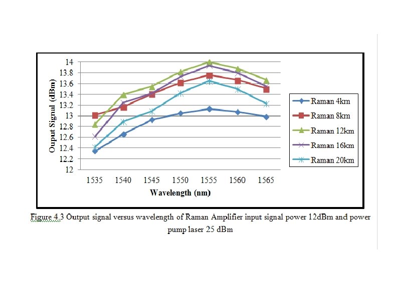
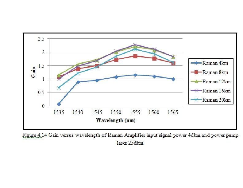
Output spectrum after the Raman 20 km + EDF 5 m for 4 d. Bm and 12 d. Bm
Output spectrum EDF 5 m and Raman 20 km for 4 d. Bm and 12 d. Bm
Results
Results
+ Semiconductor Optical Amplifiers
Semiconductor Optical Amplifier �An electrical current is passed through the device that excites electrons in the ac, ve region. �When photons (light) travel through the ac, ve region it can cause these electrons to lose some of their extra energy in the form of more photons that match the wavelength of the ini, al ones. �Therefore, an op, cal signal passing through the ac, ve region is amplified and is said to have experienced "gain. " • Both edges (or "facets") of the SOA are designed to have very low reflec, vity so that there are no unwanted reflec, ons of the signal within the semiconductor itself. • This is the main difference from regular lasers that have reflec, ve facets in order to build up the intensity of light within the semiconductor material.
SOA : : Amplification Process �Semiconductors �At have Valence and Conduc, on bands thermal equilibrium valence band has higher popula, on �Under popula, on inversion condi, on conduc, on band will have higher popula, on �Popula, on E 2 inversion is achieved by forward biasing the p-n junc, on Conduction Band signal E 1 Valence Band electron hole
SOA : : Design
SOA vs Semiconductor Laser �Both are very similar in principle and construc, on �Essen, ally Fabry-Perot cavi, es, with amplifica, on achieved by external pumping �The key in SOA is preven, ng self-oscilla, ons genera, ng laser output �This is accomplished by blocking cavity reflec, ons using both an an, reflec, on (AR) coa, ng and the technique of angle cleaving the chip facets. �SOAs are electrically pumped by injected current
SOA : : Characteristics �Compact > only a small semiconductor chip with electrical and fiber connec, ons. �The output powers are significantly smaller. �The gain bandwidth is smaller, but devices opera, ng in different wavelength regions can be made. � The upper-state life, me and thus the stored energy are much smaller, so that the gain reacts to changes in pump power or signal power within nanoseconds (instead of milliseconds). �Changes in gain also cause phase changes leading to linewidth enhancement factor. �SOAs exhibit much stronger nonlinear distor, ons {self-phase modula, on and four-wave mixing}. � The noise figure is typically higher. � The amplifica, on is normally polariza, on-sensi, ve.
SOA : : Gain vs Signal Power �In SOAs the gain dynamics are determined by the carrier recombina, on life, me (few hundred picoseconds). �The amplifier gain will react rela, vely quickly to changes in the input signal power. �This dynamic gain cause signal distor, on, which becomes more severe as the modulated signal bandwidth increases. �These effects are even more important in mul, channel systems where the dynamic gain leads to interchannel crosstalk. �This is in contrast to EDFAs, which have recombina, on life, mes of the order of milliseconds leading to negligible signal distor, on. �SOAs also exhibit nonlinear behaviour => problems such as frequency chirping and genera, on of intermodula, on products. �Nonlineari, es can also be of use in SOAs as func, onal devices such as wavelength converters.
SOA : : Applications �Power booster - Immediately a`er Laser Diode �In-line amplifier �Detector preamplifier �Op, cal switching element �Wavelength converter
Optical Amplifiers : Comparison Property EDFA Raman SOA Gain (d. B) > 40 > 25 >30 Wavelength (nm) 1530 -1560 1280 -1650 Bandwidth (3 d. B) 30 -60 Pump dependent 60 Max. Saturation (d. Bm) 22 0. 75 × pump 18 Polarization Sensitivity No No Yes Noise Figure (d. B) 5 5 8 Pump Power 25 d. Bm >30 d. Bm < 400 m. A Time Constant 10 -2 s 10 -15 s 2 x 10 -9 Size Rack mounted Bulk module Compact Switchable No No Yes Cost Factor Medium High Low
Considerations �Power booster : Placed immediately a`er transmier. Help increase the power of the signal, noise may not be the major issue �SOA �In-line amplifier : Compensate for the signal aenua, on as it propagates. Needed in long-haul networks. Noise plays a considerable role as the signal weakens �Combina, on of EDFA, Filters and Raman Amplifiers �Preamplifier : A weak op, cal signal is usually amplified before it enters the receiver. Noise is a crucial factor Power Booster Transmitter In-line Amplifier 100 km Receiver Detector Pre-amplifier
Other doped fiber amplifiers Band Name Meaning Wavelength (nm) Technology O Original 1260 -1360 Praseodymium E Extended 1360 -1460 - S Short 1460 -1530 Thulium fiber C Conventional 1530 -1565 Erbium fiber L Long 1565 -1625 Erbium fiber U Ultra-long 1625 -1675 -
References �Erbium-Doped Fiber Amplifiers by Philippe C. Becker, N. Anders Olsson, and Jay R. Simpson �Rare-Earth-Doped Fiber Lasers and Amplifiers, Revised and Expanded by Michel J. F. Digonnet �Raman Amplifica, on in Fiber Op, cal Communica, on Systems (by Clifford Headley and Govind Agrawal �Raman Amplifiers for Telecommunica, ons 1: Physical Principles by Mohammad N. Islam �Raman amplifica, on design in WDM systems, Web Proforum Tutorials, hp: //www. iec. org and various internet resources