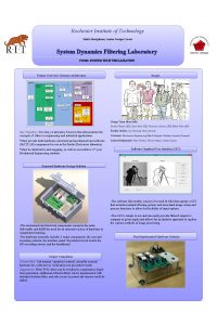
Multidisciplinary Senior Design Rochester Institute of Technology DresserRand


- Slides: 22

Multidisciplinary Senior Design Rochester Institute of Technology Dresser-Rand Painted Post P 10459 Systems Level Design Review 1/22/10 Team: Phil Eaton (ME) Alex Frenkel (ME) Rachel Koch (ME) Pete Lowry (ISE) Yi Xie (ISE) Faculty Guide: John Kaemmerlen

Expectations • Discussion • • Feedback on current status Suggestions for improvement Different thoughts/points to consider Clear view of next steps

Background • Problem • Liner cell is located in 3 different parts of the plant • One part is in a location that will be closed off • Objective • Provide a detailed plan for movement/consolidation • Maximize productivity, safety, quality, and profitability in new layout • Time Frame • MSD I: Nov. 30, 2009 – Feb. 19, 2010 • MSD II: Mar. 8, 2010 – May 14, 2010 • Stakeholders • RIT: John Kaemmerlen, Senior Design Program • D-R: Dennis Rice, Malcolm Cliff, Mike Decerbo, Chris Benesch, John Woedy, Shane Kinney

Customer Needs/Work Breakdown Need Metric Current* Marginal Target Machine Configuration (Alex) Overhead Cost $87, 991 -10% -20% Process Time 30 days <=25 days <=15 days Man Power 6 4 3 Defect Cost $40, 623 -10% -15% Cell Layout (Pete) Travel Distance 1, 280 ft -40% -50% Process Time 30 days <=28 days <=25 days Process Improvement (Yi) # Injuries 0 0 0 Process Time 30 days <=28 days <=25 days Defect Cost $40, 623 -10% -20% Material Handling (Rachel) Defect Cost $40, 623 -20% -25% Material Storage (Phil) Space Utilization 6584 sq ft -20% -30% Travel Distance 1, 280 ft -10% -20% *Based on 2009 Metrics (Jan – Sep)

Systems Level Design Mechanical Engineering Alex Machine Configuration Cell Layout Method Industrial Engineering Pete Rachel Phil Material Handling Material Storage Problem Solving Man Visual Controls Metrics Yi New Layout with best safety, productivity and quality

Machine Configuration o Goal: Determine the optimal configuration of machines to reduce production time and cost. o Options o Keep the old machines, Liner cell needs to be moved anyway, savings will come by consolidating these machines and figuring out a good layout o Buy a new CNC VTL, we are looking at some machines that are capable of doing most of the steps in the process, reducing set up time. R· I· T Mechanical Engineering Department

Machine Configuration o Preferred Machine Specifications o Capable of running any liner from 14 in up to 42 in o Chuck size around 50 in o Maximum tooling height around 60 in o Live Tooling o Reducing changeover time in operations o Horizontal milling attachment o Can be used for porting o Must have x and y axis capabilities o Inspection probe o Inspect liner inside the machine so that the operator does not have to pull it out to do the inspection process. R· I· T Mechanical Engineering Department

Machine Configuration o Benefits of a new CNC VTL o Eliminate the grinding operation o Possibly eliminate the bore sheet and machine part to the print instead o Reduce operator errors o Ultimately the deciding criteria will come down to which option has the best return on investment over time compared to the current process. o With a new machine we think that we can cut production time, cost and man power. o The new configuration will also be versatile enough to handle higher work loads. R· I· T Mechanical Engineering Department

Cell Layout o Moving Shop 21’s Liner Cell to Shop 6 and 17 o Planned Improvements: o Greatly reduced travel time and distance (Present Base Route seen here) o A more centered layout o Improve Product flow R· I· T Mechanical Engineering Department

Cell Layout o The Probable Options o “As Is” process: o Use of the same machines presently being used o No new machines added o “Improved” process: o Replacement of the grinder with a vertical turning lathe (VTL) o The grinder will become unnecessary o “Re-Developed” process o Purchasing and using a multi-axis CNC machine as part of the main process flow. o Present tools will be kept to back up the CNC R· I· T Mechanical Engineering Department

Cell Layout o Possible looks at Re-layouts o Many factors to still consider: o Which unused machines can we scrap and replace? o Use or need of high and low bay space R· I· T Mechanical Engineering Department

Process Improvement Goal: • Provide visibility to management and operators on metrics: – Safety – Productivity – Quality • 6 S for a clean and sustainable workplace • Standard work for consistent process, easy training and identification of out of standard process. • Provide environment for continuous improvement R· I· T Mechanical Engineering Department

Process Improvement Why? • Operators – – Simplified process Able to detect and prevent defects Understand status of part/line at all times Safer workplace • Managers – Have knowledge of part/line status at all times – Immediately detect out of standard conditions – Easy to train new operators, cross train current R· I· T Mechanical Engineering Department

Process Improvement How? • Metrics – Productivity (On time delivery, output/day, part status, cycle time, down time, weekly schedule) – Safety (Safe work days, accidents) – Quality (Defects, number good parts) • 6 S – Labeled tool storage, machine locations, floor markers, cleaning schedule, audits • Standard Work – Work charts, combination tables • Continuous improvement – Problem solving board w/ lean training – Morning market R· I· T Mechanical Engineering Department

Material Handling o Current Material Handling Procedure: o Liners set vertically onto wooden pallets, moved by forklift o Causes parts to fall if forklift must stop short, resulting in defects o Current Defect Cost: $40, 632 (Jan-Sep 2009) o Concerns: o Safety o Ease of Travel o Minimize Product Defects o Secure liners during travel R· I· T o Support Adequate Load o Largest drum dimensions: o 42” OD x 55” tall o 2000 lb weight Mechanical Engineering Department

Material Handling Pallet Fixture/Modification o Create fixture for pallets: Flat piece with indentation to allow liner to settle, secure with ratchet straps o Modify wooden pallets: Remove center pieces of pallet to allow liner to settle, secure with ratchet straps http: //en. wikipedia. org/wiki/Drum_%28 container%29 R· I· T Mechanical Engineering Department

Material Handling o Moving Shop 21’s Liner Cell to Shop 6 and/or 17 o Dimensions o 48" x 36" o Features: o 10, 000 lb rated ratchet strap attaches at 3 different heights o Can be moved using forklift o Doubles as storage unit *Designed originally for gas cylinders Cost: $812 http: //www. usasafety. com/gas-cylinder-transport-pallet-forklift-21 -cylinders-p-49. html R· I· T Mechanical Engineering Department

Material Storage o Functions of Drum Rack o Support load of drums o Each shelf can support 4, 825 lb o Total capacity is 14, 475 lb o Restrict drum movement o Individual Brackets o Safety o Built to OSHA standards Cost - $608. 25 ea. • http: //www. materialflow. com/index. cfm? mf=browse. show. Part&part. Class. ID=670&PName=Drum%20 Pallet%20 Racks R· I· T Mechanical Engineering Department

Material Storage o Dual Purpose o Drum rack could be used for liners o Standard drum dimensions o 22. 5” OD x 34. 5” tall o Modifications needed: o Deeper shelf for liners o Support for large OD liners o Interchangeable brackets http: //en. wikipedia. org/wiki/Drum_%28 container%29 R· I· T Mechanical Engineering Department

Material Storage o Cart designed for liners o Largest drum dimensions o 42” OD x 55” tall o 2000 lb weight o Features: o Mobility for liners o Support for large OD liners o Doubles as storage unit o Liners stored vertically o Take up less space (4’ x 4’) o Will not interrupt walkway R· I· T Mechanical Engineering Department

Risk Assessment Risk Importance* Action to mitigate Design doesn’t meet needs 6 Weekly meetings with management, be open to criticism/suggestions Operators don’t accept new system 6 Weekly meetings with operators, use their input if possible Injury of RIT or D-R team member 6 Review safety procedures, do not distract others when working Design exceeds budget 4 Budget review meeting Maintenance of tools/process after completion 4 Documentation of processes and tools, obtain buy in from all parties, build to last years Layout drawings don’t reflect reality 3 Verify drawings with actual measurements, double check measurements Down time during movement 3 Detailed cutover plan with anticipated down times *Based on Severity (1 -3) x Likelihood (1 -3). 1= lowest, 9= highest

Project Plan
 Uksn almora
 Reflection on multidisciplinary team
 Temasek laboratories
 Multidisciplinary vs interdisciplinary
 Multidisciplinary interdisciplinary and transdisciplinary
 Sunderlal bahuguna quotes malayalam
 Multidisciplinary software development team
 Conflict in multidisciplinary teams
 Multisectoral and multidisciplinary
 Interdisciplinary multidisciplinary transdisciplinary
 Multidisciplinary studies epcc
 Dr. fernando cosio rochester mn
 Edra rochester
 Lattimore hall university of rochester
 Criterios de rochester fiebre sin foco
 Mbhs moodle
 Eastman business park map
 Csc 282
 Rochester first time home buyer
 Mesulid şurup
 çağrı safa buyurgan
 Rochester kriterleri
 Felicia reed watt

