Module contents Antenna systems RF propagation RF prop
- Slides: 32
Module contents « Antenna systems « RF propagation RF prop. 1
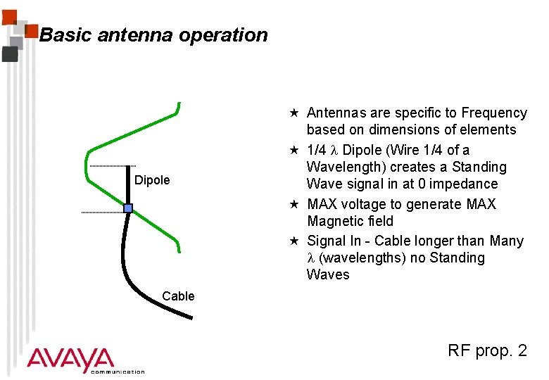
Basic antenna operation Dipole « Antennas are specific to Frequency based on dimensions of elements « 1/4 Dipole (Wire 1/4 of a Wavelength) creates a Standing Wave signal in at 0 impedance « MAX voltage to generate MAX Magnetic field « Signal In - Cable longer than Many (wavelengths) no Standing Waves Cable RF prop. 2
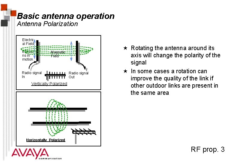
Basic antenna operation Antenna Polarization Electric al Field Electro ns in motion Magnetic Field Radio signal In Vertically Polarized Radio signal Out « Rotating the antenna around its axis will change the polarity of the signal « In some cases a rotation can improve the quality of the link if other outdoor links are present in the same area Horizontally Polarized RF prop. 3
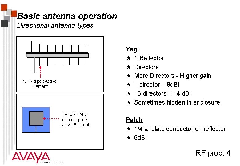
Basic antenna operation Directional antenna types Yagi « 1 Reflector « Directors « More Directors - Higher gain « 1 director = 8 d. Bi « 15 directors = 14 d. Bi « Sometimes hidden in enclosure 1/4 dipole. Active Element 1/4 X 1/4 infinite dipoles Active Element Patch « 1/4 plate conductor on reflector « 6 d. Bi RF prop. 4
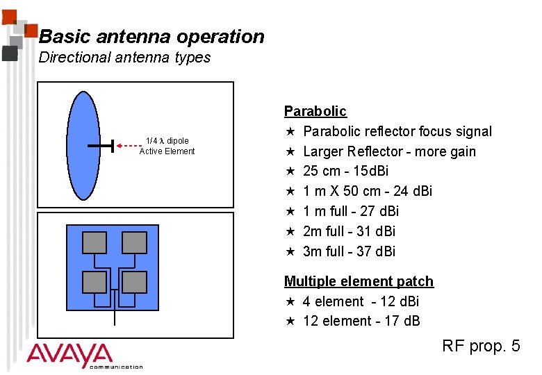
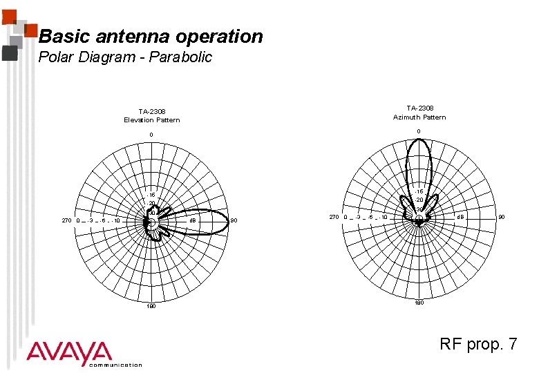
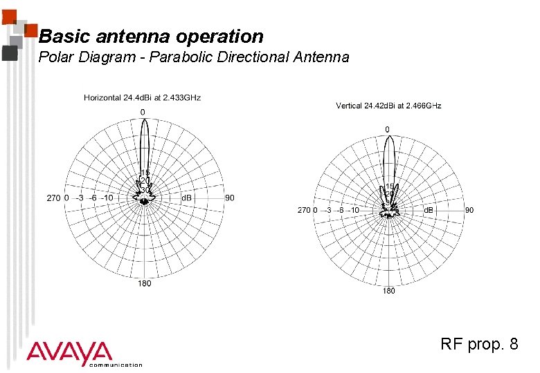
Basic antenna operation Directional antenna types 1/4 dipole Active Element Parabolic « Parabolic reflector focus signal « Larger Reflector - more gain « 25 cm - 15 d. Bi « 1 m X 50 cm - 24 d. Bi « 1 m full - 27 d. Bi « 2 m full - 31 d. Bi « 3 m full - 37 d. Bi Multiple element patch « 4 element - 12 d. Bi « 12 element - 17 d. B RF prop. 5
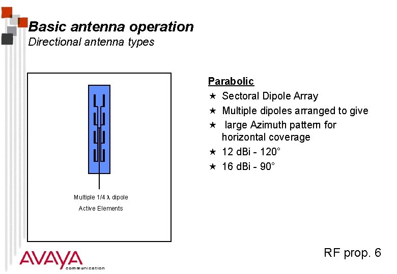
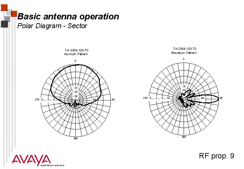
Basic antenna operation Directional antenna types Parabolic « Sectoral Dipole Array « Multiple dipoles arranged to give « large Azimuth pattern for horizontal coverage « 12 d. Bi - 120° « 16 d. Bi - 90° Multiple 1/4 dipole Active Elements RF prop. 6
Basic antenna operation Polar Diagram - Parabolic TA-2308 Azimuth Pattern TA-2308 Elevation Pattern 0 0 -15 -20 -30 270 0 -3 -6 -10 d. B 180 90 270 0 -3 -6 -10 d. B 90 180 RF prop. 7
Basic antenna operation Polar Diagram - Parabolic Directional Antenna RF prop. 8
Basic antenna operation Polar Diagram - Sector TA-2304 -120 -T 0 Elevation Pattern TA-2304 -120 -T 0 Azimuth Pattern 0 0 -15 -20 -30 270 0 -3 -6 -10 d. B 180 90 270 0 -3 -6 -10 d. B 90 180 RF prop. 9
Basic antenna operation Antenna Specifications « Gain in d. Bi « Pattern , Azimuth (Horizontal) and Elevation (Vertical) shown in Polar diagram d. B loss per angle « Impedance at operating Frequency (50 ohms) « Bandwidth, gain vs frequency graph « Front to back ratio - signal behind a directional antenna « Mechanical properties, weather resistance, mounting methods RF prop. 10
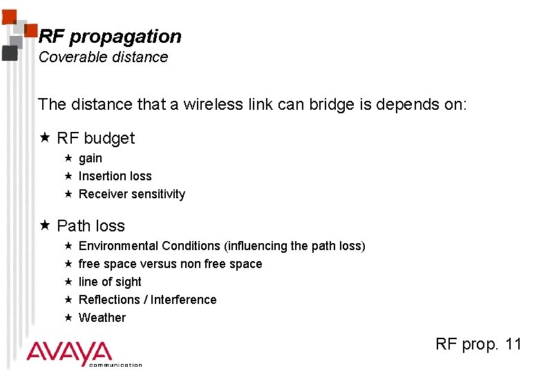
RF propagation Coverable distance The distance that a wireless link can bridge is depends on: « RF budget « gain « Insertion loss « Receiver sensitivity « Path loss « « « Environmental Conditions (influencing the path loss) free space versus non free space line of sight Reflections / Interference Weather RF prop. 11
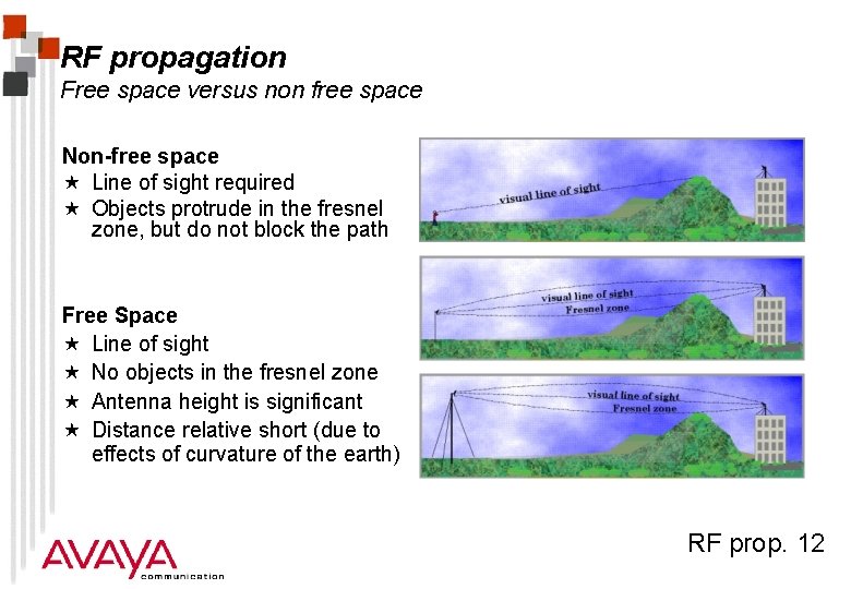
RF propagation Free space versus non free space Non-free space « Line of sight required « Objects protrude in the fresnel zone, but do not block the path Free Space « Line of sight « No objects in the fresnel zone « Antenna height is significant « Distance relative short (due to effects of curvature of the earth) RF prop. 12
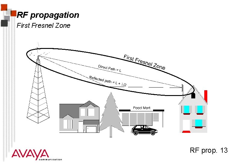
RF propagation First Fresnel Zone RF prop. 13
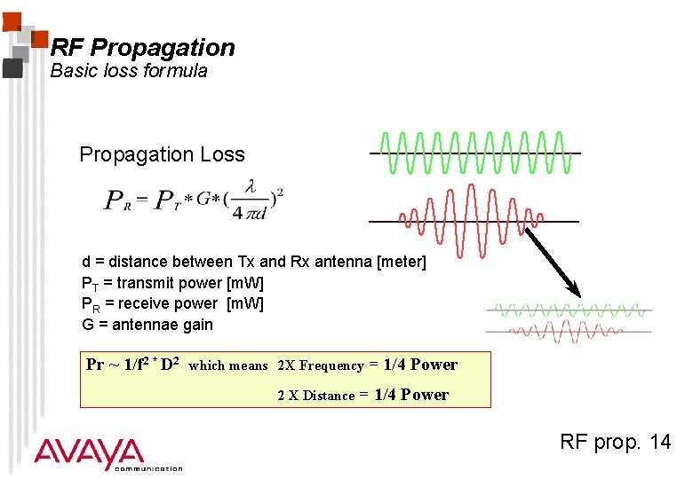
RF Propagation Basic loss formula Propagation Loss d = distance between Tx and Rx antenna [meter] PT = transmit power [m. W] PR = receive power [m. W] G = antennae gain Pr ~ 1/f 2 * D 2 which means 2 X Frequency 2 X Distance = 1/4 Power RF prop. 14
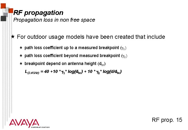
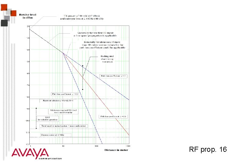
RF propagation Propagation loss in non free space « For outdoor usage models have been created that include « path loss coefficient up to a measured breakpoint (g 1) « path loss coefficient beyond measured breakpoint (g 2) « breakpoint depend on antenna height (dbr) L(2. 4 GHz) = 40 +10 * g 1* log(dbr) + 10 * g 2* log(d/dbr) RF prop. 15
RF prop. 16
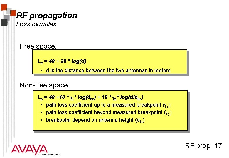
RF propagation Loss formulas Free space: Lp = 40 + 20 * log(d) • d is the distance between the two antennas in meters Non-free space: Lp = 40 +10 * g 1* log(dbr) + 10 * g 2* log(d/dbr) • path loss coefficient up to a measured breakpoint (g 1) • path loss coefficient beyond measured breakpoint (g 2) • breakpoint depend on antenna height (dbr) RF prop. 17
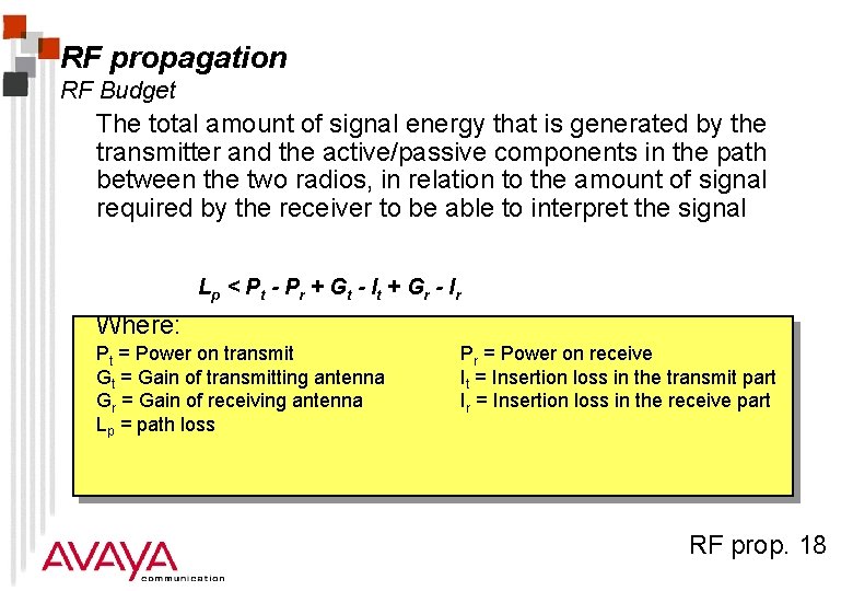
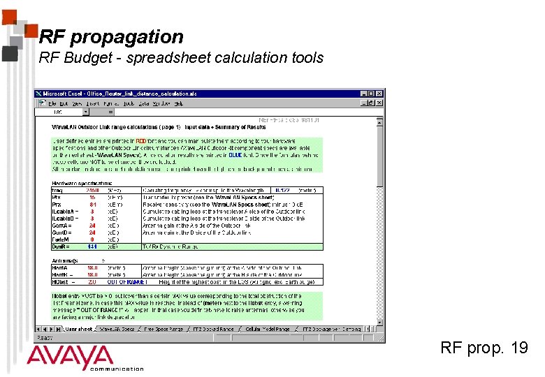
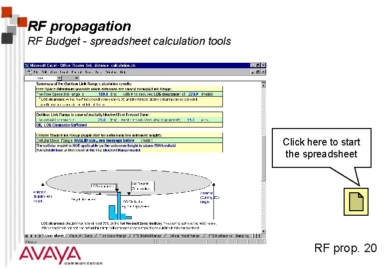
RF propagation RF Budget The total amount of signal energy that is generated by the transmitter and the active/passive components in the path between the two radios, in relation to the amount of signal required by the receiver to be able to interpret the signal Lp < P t - P r + G t - I t + G r - I r Where: Pt = Power on transmit Gt = Gain of transmitting antenna Gr = Gain of receiving antenna Lp = path loss Pr = Power on receive It = Insertion loss in the transmit part Ir = Insertion loss in the receive part RF prop. 18
RF propagation RF Budget - spreadsheet calculation tools RF prop. 19
RF propagation RF Budget - spreadsheet calculation tools Click here to start the spreadsheet RF prop. 20
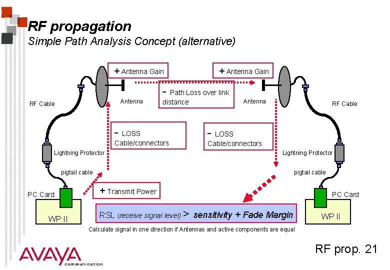
RF propagation Simple Path Analysis Concept (alternative) + Antenna Gain - Path Loss over link Antenna RF Cable - LOSS Cable/connectors Lightning Protector Antenna distance RF Cable - LOSS Cable/connectors Lightning Protector pigtail cable PC Card WP II pigtail cable + Transmit Power RSL (receive signal level) > sensitivity + Fade Margin PC Card WP II Calculate signal in one direction if Antennas and active components are equal RF prop. 21
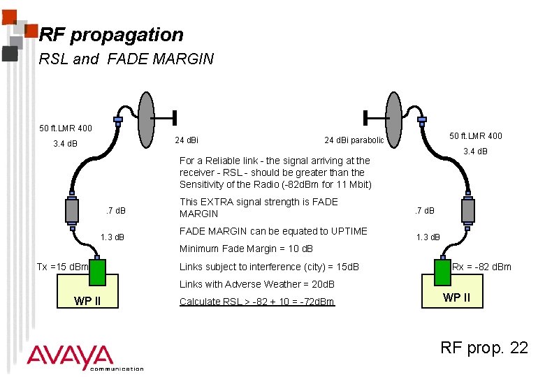
RF propagation RSL and FADE MARGIN 50 ft. LMR 400 24 d. Bi 3. 4 d. B 50 ft. LMR 400 24 d. Bi parabolic 3. 4 d. B For a Reliable link - the signal arriving at the receiver - RSL - should be greater than the Sensitivity of the Radio (-82 d. Bm for 11 Mbit). 7 d. B 1. 3 d. B This EXTRA signal strength is FADE MARGIN can be equated to UPTIME . 7 d. B 1. 3 d. B Minimum Fade Margin = 10 d. B Tx =15 d. Bm Links subject to interference (city) = 15 d. B Rx = -82 d. Bm Links with Adverse Weather = 20 d. B WP II Calculate RSL > -82 + 10 = -72 d. Bm WP II RF prop. 22
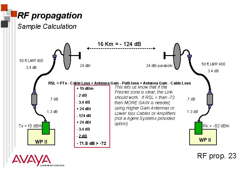
RF propagation Sample Calculation 16 Km = - 124 d. B 50 ft. LMR 400 24 d. Bi 3. 4 d. B 50 ft. LMR 400 24 d. Bi parabolic 3. 4 d. B RSL > PTx - Cable Loss + Antenna Gain - Path loss + Antenna Gain - Cable Loss This lets us know that if the + 15 d. Bm. 7 d. B 1. 3 d. B Tx =15 d. Bm - 2 d. B - 3. 4 d. B + 24 d. Bi - 124 d. B + 24 d. Bi - 3. 4 d. B - 2 d. B WP II - 71. 8 d. B > -72 Fresnel zone is clear, the Link should work. If RSL < than -72 then MORE GAIN is needed, using Higher Gain Antennas or Lower loss Cables or Amplifiers (not a Agere Systems provided option) . 7 d. B 1. 3 d. B Rx = -82 d. Bm WP II RF prop. 23
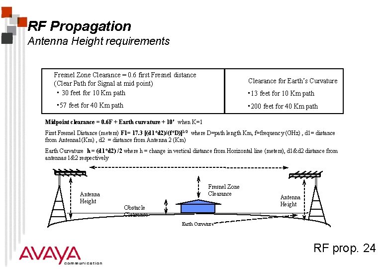
RF Propagation Antenna Height requirements Fresnel Zone Clearance = 0. 6 first Fresnel distance (Clear Path for Signal at mid point) • 30 feet for 10 Km path Clearance for Earth’s Curvature • 13 feet for 10 Km path • 57 feet for 40 Km path • 200 feet for 40 Km path Midpoint clearance = 0. 6 F + Earth curvature + 10' when K=1 First Fresnel Distance (meters) F 1= 17. 3 [(d 1*d 2)/(f*D)]1/2 where D=path length Km, f=frequency (GHz) , d 1= distance from Antenna 1(Km) , d 2 = distance from Antenna 2 (Km) Earth Curvature h = (d 1*d 2) /2 where h = change in vertical distance from Horizontal line (meters), d 1&d 2 distance from antennas 1&2 respectively Antenna Height Fresnel Zone Clearance Obstacle Clearance Antenna Height Earth Curvature RF prop. 24
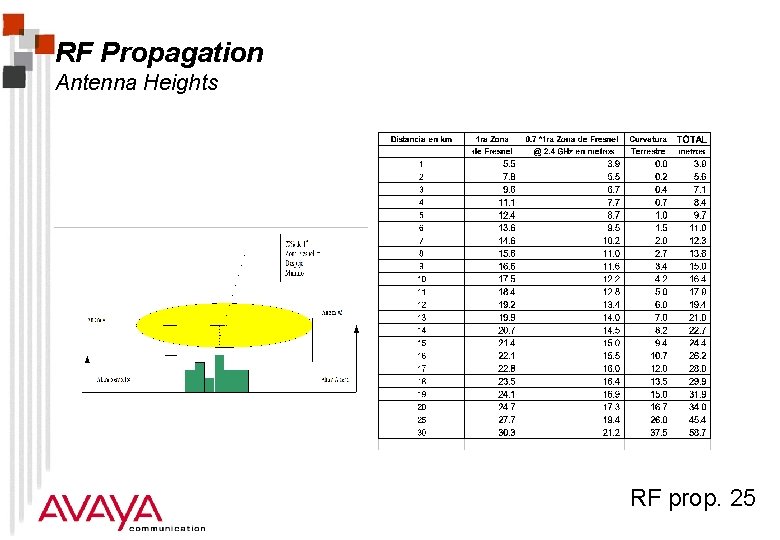
RF Propagation Antenna Heights RF prop. 25
RF Propagation Antenna Heights vs. Range Fundamental limitation of technology is the requirement for very High Antenna Heights for full Fresnel zone clearance - But this requires more cable, thus more loss and thus less Range - NO FREE LUNCH. Suggestions: « Use better quality cable (lower loss per foot) LMR 400 = 6. 8 d. B 100 ft, LMR 600 = 4. 5 d. B/100 ft, LMR 1800 = 2. 5 d. B/100 ft, 2 1/4” Helix =. 98 d. B foot BUT the better cable the harder to install (large and inflexible) and the more expensive. « Remote mount the AP-1000 in a Environmental Box (ventilated) and drop UTP of Fiber into building - requires Lightning protection and 110 VAC BUT Maintenance requires climbing Tower. « Use remote Mounted amplifiers (not available from Agere Systems) to overcome the cable loss. Amplifiers still have minimum input power requirements so better cable may still be needed for long runs. Amplifiers are specified by Max transmit Power (1/2 or 1 Watt), Tx Gain, Rx Gain, Input signal levels BUT amplifiers add noise to the system and may not actually increase SNR as much as expected - also they are another point of failure. RF prop. 26
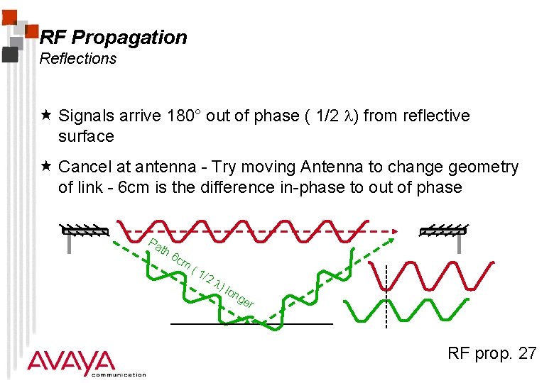
RF Propagation Reflections « Signals arrive 180° out of phase ( 1/2 ) from reflective surface « Cancel at antenna - Try moving Antenna to change geometry of link - 6 cm is the difference in-phase to out of phase Pa th 6 c m (1 /2 ) lon ge r RF prop. 27
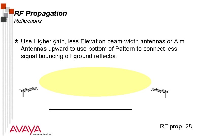
RF Propagation Reflections « Use Higher gain, less Elevation beam-width antennas or Aim Antennas upward to use bottom of Pattern to connect less signal bouncing off ground reflector. RF prop. 28
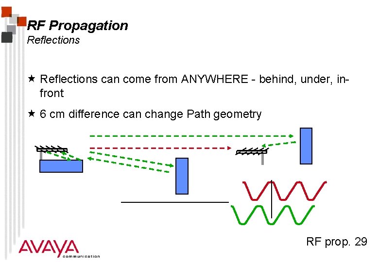
RF Propagation Reflections « Reflections can come from ANYWHERE - behind, under, infront « 6 cm difference can change Path geometry RF prop. 29
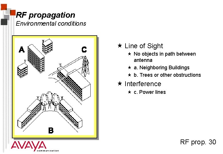
RF propagation Environmental conditions « Line of Sight « No objects in path between antenna « a. Neighboring Buildings « b. Trees or other obstructions « Interference « c. Power lines RF prop. 30
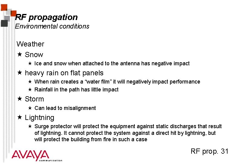
RF propagation Environmental conditions Weather « Snow « Ice and snow when attached to the antenna has negative impact « heavy rain on flat panels « When rain creates a “water film” it will negatively impact performance « Rainfall in the path has little impact « Storm « Can lead to misalignment « Lightning « Surge protector will protect the equipment against static discharges that result of lightning. It cannot protect the system against a direct hit by lightning, but will protect the building from fire in such a case RF prop. 31
Module Summary « Antenna systems « RF propagation RF prop. 32