Lecture A 3 Damping Rings Damping rings lattice


- Slides: 48

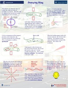
Lecture A 3: Damping Rings Damping rings’ lattice design Damping rings, Linear Collider School 2015 Yannis PAPAPHILIPPOU Accelerator and Beam Physics group Beams Department CERN Ninth International Accelerator School for Linear Colliders 26 October – 6 November 2015, Whistler BC, Canada 1

Outline n Equilibrium emittances and optics conditions for different cells q FODO Damping rings, Linear Collider School 2015 q Double Bend Achromat (DBA) q Theoretical Minimum Emittance (TME) q Multi-Bend Achromat (MBA) q Examples from low emittance rings n Wiggler effect in DR parameters q Radiation integrals, energy loss/turn, damping times, energy spread, bunch length, transverse emittance n The ILC and CLIC DR optics 2

Equilibrium emittance reminder Damping rings, Linear Collider School 2015 with the dispersion emittance defined as n For isomagnetic ring with separated function magnets the equilibrium emittance is written n Smaller bending angle and lower energy reduces emittance n For evaluating the dispersion emittance, the knowledge of the 3 lattice function is necessary

Optics functions in a FODO cell n Some basic assumptions Quadrupoles are represented by thin lenses q The absolute value of their focal length is the same q The space between quadrupoles is filled completely by dipoles with bending radius and length and bending angle Damping rings, Linear Collider School 2015 q n With these approximations, the horizontal beta function at the focusing quadrupole is n. The dispersion at the same location is n From symmetry, 4

Optics through the FODO n Consider the transfer matrix and the “optics” matrix Damping rings, Linear Collider School 2015 n The evolution of the optics function between to points s 0 and s 1 is n The dispersion propagation over a distance with constant bending radius is given by n The transfer matrices to be used for the quadrupole and dipole are and 5

Damping rings, Linear Collider School 2015 Radiation integrals for a FODO n The 5 th radiation integral can be determined by computing the “curly-H” function evolution along the dipole and integrating to get the mean value n. The algebra is quite involved and it is useful to take the expansion in power series over the bending angle which gives 6

Radiation integrals for a FODO II n Some approximations q For small bending angle q Damping rings, Linear Collider School 2015 q. Considering q that Imposing also (true in most cases) (somehow more restrictive) 7

Emittance for a FODO cell Damping rings, Linear Collider School 2015 n With no quadrupole component in the dipole n The FODO natural emittance can be approximated as n As already seen, the emittance is scaled to the square of energy, but also proportional to the cube of bending angle (more cells and a lot of dipoles) n The emittance is proportional to the cube of focal length, i. e. stronger quadrupoles reduce emittance n The emittance is inversely proportional to the cube 8 of dipole (or cell) length, the longest the cell the

Minimum Emittance for FODO cell n. The phase advance in a FODO is written as imposing the stability condition Damping rings, Linear Collider School 2015 n The minimum focal length is obtained for and it is n. An approximated value of the minimum emittance for a FODO is then n This approximation is indeed breaking down for very high quadrupole strengths (small focal lengths) 9

Minimum Emittance for FODO cell II Damping rings, Linear Collider School 2015 n It can be shown that the actual minimum for a FODO cell is for a phase advance of n This sets the minimum emittance of a FODO cell to 10

Damping rings, Linear Collider School 2015 An exotic example: SPS low emittance optics n SPS is a 7 km ring with an all FODO cell lattice (6 sextants), with missing dipole n There are 696 dipoles n Usually tuned to 90 deg. phase advance for fixed target beams (Q 26) and since 2012 to 67. 5 deg (Q 20) for LHC beams n Move horizontal phase advance to 135(3π/4) deg. (Q 40) n Normalized emittance with nominal optics @ 3. 5 Ge. V of 23. 5μm drops to 9μm (1. 3 nm geometrical) Mainly due to dispersion decrease q Almost the normalized emittance of ILC damping rings but still twice the geometrical. q n Damping times of 9 s n Natural chromaticities of -71, -39 (from 20, -27) 11

Minimum Emittance for FODO cell II Damping rings, Linear Collider School 2015 n The previous examples is actually demonstrating that getting a really small emittance with a FODO cell, a very long ring is needed n There was no special effort though for minimizing the dispersion emittance, which is almost flat along a dipole 12

Optics functions through a bend n Consider the transport matrix of a bending magnet (ignoring edge focusing) Damping rings, Linear Collider School 2015 n Consider at its entrance the initial optics functions n The evolution of the twiss functions, dispersion and dispersion derivative are given by 13

Average dispersion emittance n The dispersion emittance through the dipole is written as Damping rings, Linear Collider School 2015 and its average along the dipole of length l 14

Optics functions for minimum emittance Damping rings, Linear Collider School 2015 n Take the derivative of the dispersion emittance with respect to the initial optics functions and equate it to zero to find the minimum conditions n Non-zero dispersion (general case) and n Zero dispersion (and its derivative) 15

Minimum emittance conditions n In the general case, the equilibrium emittance takes the form 2 2 and expanding on θ we have n In the 0 -dispersion case, Damping rings, Linear Collider School 2015 2 2 n The second order term is negligible (less the 1% for θ < 20 deg. ) n Note that in both cases the emittance depends on the 3 rd power of the bending angle n The emittance for non-zero dispersion is 3 times smaller 16

Damping rings, Linear Collider School 2015 Optics functions for minimum emittance 17

Deviation from the minimum emittance n Introduce the dimensionless quantities and Damping rings, Linear Collider School 2015 n Introduce them into the expression of the mean dispersion emittance to get n The curves of equal relative emittance are ellipses n The phase advance for a mirror symmetric cell is n The optimum phase advance for reaching the minimum emittance (F=1) is unique (284. 5 o)! 18

Low emittance lattices dispersion n Double Bend Achromat (DBA) Damping rings, Linear Collider School 2015 n Triple Bend Achromat (TBA) n Quadruple Bend Achromat (QBA) n Minimum Emittance Lattice (MEL) 19

Chasmann-Green cell Damping rings, Linear Collider School 2015 n Double bend achromat with unique central quadrupole n Achromatic condition is assured by tuning the central quadrupole n Minimum emittance with a quadrupole doublet in either side of the bends n The required focal length of the quad is given by and the dispersion n Disadvantage the limited tunability and reduced space 20

Damping rings, Linear Collider School 2015 DBA with triplet n Central triplet between the two bends and two triplets in the straight section to achieve the minimum emittance and achromatic condition n Elettra (Trieste) uses this lattice achieving almost the absolute minimum emittance for an achromat 21 n Disadvantage the increased space in between the bends

Damping rings, Linear Collider School 2015 Expanded DBA n Original lattice of ESRF storage ring, with 4 quadrupoles in between the bends n Alternating moderate and low beta in intertions 22

Damping rings, Linear Collider School 2015 Theoretical minimum emittance optics n Old Super-Aco ring could operate in a theoretical minimum emittance optics n The most popular structure for damping 23 rings

Damping rings, Linear Collider School 2015 Natural emittance for different lattice cells 24

Damping rings, Linear Collider School 2015 Combining DBA and TME n Most of the rings would benefit from areas with zero dispersion for placing special equipment including beam transfer, RF and damping wigglers n A combination of TME in between dipoles were dispersion vanishes would be beneficial n These Multi-bend achromats (MBA) are the latest trend of X -ray storage rings upgrade projects n Consider the simple case with variable lengths but same bending radius, and M dipoles n The bending angles then satisfies the condition 25

Multi-bend achromat emittance n The radiation integrals are additive quantities so they are and Damping rings, Linear Collider School 2015 n Their ratio is given by n It is minimized for the following conditions n This implies that the central bends are longer by a factor of n The minimum natural emittance is given by 26

Triple Bend Achromat n Three bends with the central one with theoretical minimum emittance conditions n Strict relationship between the bending angles and lengths Damping rings, Linear Collider School 2015 of dipoles in order to achieve dispersion matching n A unique phase advance of 255 o is needed for reaching the minimum emittance n This minimum is double with respect to the TME one n Example, the Swiss Light Source 27

Damping rings, Linear Collider School 2015 Seven-Bend achromat: MAXIV n Very compact ring design with vertical focusing provided by including gradient in the bending magnets 28

Damping rings, Linear Collider School 2015 Summary of lattice performance 29

Damping rings, Linear Collider School 2015 Damping wigglers n A wiggler magnet is a magnetic device producing a vertical field which alternates in polarity along the beam direction. n In general, wiggler magnets give rise to both radiation damping and quantum excitation n They result in different equilibrium values of damping times emittance and energy spread which depend both on the wiggler magnet parameters and on the lattice functions through the wiggler n In the first order approximation, the vertical field component of a wiggler raises along the beam axis is with 30

Radiation integrals for damping wigglers Damping rings, Linear Collider School 2015 n The contribution from a wiggler to the ith synchrotron integrals can be written as with and the synchrotron integrals produced in the arcs and in the wigglers n Assuming that wiggler magnets with sinusoidal field variation are installed in the dispersion free region of the ring, the radiation integrals for the wigglers can be written with the wiggler length equal to , i. e the product of wiggler period length and the number of periods n The 4 th and 5 th radiation integrals arise from the dispersion generated by the wiggler magnet (self-dispersion), although the 4 th is quite small for small wiggler periods 31

Relative damping factor Damping rings, Linear Collider School 2015 n The change of the damping rate due to the wiggler is conventionally defined by the relative damping factor with the bending field of the arc dipoles. When the damping is dominantly achieved by the wigglers n The energy loss per turn is n The horizontal damping partition number is and still very close to 1 for wiggler dominated rings 32

Damping times with wigglers Damping rings, Linear Collider School 2015 n The damping times are very influenced in a large extend by the damping wigglers with 33

Equilibrium emittance with wigglers Damping rings, Linear Collider School 2015 n Assuming that the 5 th radiation give is small, the largest dominant term for Sinusoidal field model hard-edge field model n Assuming the hard-edge model, the emittance in a wiggler dominated ring with TME arc cells can be written as n This approximation ignores the details of the dispersion suppressor optics at the start and end of the arcs, but is still a fairly accurate description, especially when the number of TME cells per arc is large 34

Energy spread and mom. compaction Damping rings, Linear Collider School 2015 n The equilibrium rms energy spread is n The equilibrium bunch length depends also on the momentum compaction factor and the parameters of the RF system n Considering the ratio of the emittance with respect to the absolute emittance minimum, , the momentum compaction factor with wigglers takes a complicated form 35

CLIC DR – damping times Damping rings, Linear Collider School 2015 F. Antoniou, Ph. D thesis, NTUA 2013 n To damp the beam from 63 μm-rad to 500 nm-rad in less than 20 ms a maximum damping time of 4 ms is required n Large dipole fields (or very small dipole length) q Cannot be achieved by normal conducting dipoles n Fast damping times can be achieved for large wiggler fields and/or large wiggler total length 36

Effect of damping wigglers on CLIC DR Damping rings, Linear Collider School 2015 F. Antoniou, Ph. D thesis, NTUA 2013 37

Lattice design phases n Initial preparation q Performance q Boundary conditions and constraints q Building blocks (magnets) n. Linear lattice design Build modules, and match them together q Achieve optics conditions for maximizing performance q Global quantities choice working point and chromaticity Damping rings, Linear Collider School 2015 q n. Non-linear lattice design Chromaticity correction (sextupoles) q Dynamic aperture q n. Real world q Include imperfections and foresee corrections 38

Lattice design inter-phase Damping rings, Linear Collider School 2015 Magnet Design: Technological limits, coil space, field quality Vacuum: Impedance, pressure, physical apertures, space Radiofrequency: Energy acceptance, bunch length, space Diagnostics: Beam position monitors, resolution, space Alignment: Orbit distortion and correction Mechanical engineering: Girders, vibrations Design engineering: Assembly, feasibility 39

Other devices Device Parameter Purpose RF cavities RF phase and Voltage Acceleration, phase stability Septum Position and width injection Kicker Integrated dipole field Damping rings, Linear Collider School 2015 Orbit corrector Orbit correction Quadrupole corrector Integrated quad field Restoring periodicity Skew quadrupoles Integrated skew quad field Coupling correction Undulators, wigglers Number of periods, wavelength, field and gap Synchrotron radiation Vacuum pumps Passive Keep high vacuum Beam position monitors, other instrumentation Absorbers Passive Position, beam parameters measurement Synchrotron radiation absorption 40

Damping rings, Linear Collider School 2015 The ILC DR TDR optics n The ring has a race-track shape with two arcs and two straight sections n The arc is filled with 75 TMElike cells with one additional defocusing quadrupole for tuning flexibility n The dispersion is zeroed at the end of the arc by dispersion suppressor cells (two dipoles and 7 quads) n The straight sections are filled with different type FODO cells, depending on the different function (wigglers, phase trombone, beam transfer, RF) 41

Damping rings, Linear Collider School 2015 ILC DR magnets n n n ILC DR filled with conventional electromagnets for the dipole, quadrupole, sextupole, and corrector magnets. This offers flexibility for tuning and optimizing the rings as well as for adjusting the operating beam energy by a few percent around the nominal value of 5 Ge. V. Maximum strength and field tolerances within capabilities of modern magnets 42

Damping rings, Linear Collider School 2015 The CLIC DR lattice n Racetrack configuration q q 2 arc sections filled with TME cells 2 long straight sections filled with FODO cells accommodating the damping wigglers 43

Optimized TME cell n TME cell with defocusing gradient along the dipole length q Reduction of the IBS effect n Dipole length increased Damping rings, Linear Collider School 2015 q ld=0. 58 m (from 0. 43 m) n Horizontal phase advance reduced q μx. TME=0. 408 (from 0. 452) n RF voltage decreased q VRF=5. 1 MV (from 4. 5 MV) 44

CLIC DR FODO and DS-BM cells Damping rings, Linear Collider School 2015 n FODO cells accommodate the damping wigglers (2 wigglers / cell) n Space is reserved for the absorption scheme of synchrotron radiation n Dispersion suppression – beta matching cell optics n Space is reserved for injection/extraction elements and RF cavities 45

Damping rings, Linear Collider School 2015 Geometrical acceptance of the DR n Required geometrical acceptance around the DR to fit the incoming beam n For Gaussian beams (coming from PDR) 46

Damping rings, Linear Collider School 2015 DR- magnetic parameters n Summary table of the magnet parameters of the DR n All maximum fields can be achieved by standard electromagnets (apart wigglers) 47

Damping rings, Linear Collider School 2015 Summary n Low emittance cannot be achieved with FODO cells n Special lattice cells are needed (TME or MBE) n Damping wigglers enhance emittance and damping time reduction but slightly increases longitudinal beam characteristics n Although ILC and CLIC DR parameters differ in some extent, lattice design concept is quite similar n In order to close the loop, non-linear dynamics, collective effects and technology considerations have to be taken into account 48
 Poset matematika diskrit
 01:640:244 lecture notes - lecture 15: plat, idah, farad
 Damper in suspension system
 Unececarry
 Relaxation time of damped harmonic oscillator
 Atwood's classification of residual ridges
 Graphical representation of shm
 Air friction damping
 Alpha and gamma motor neurons
 Measuring instrument definition
 Roll damping
 Application of voltmeter
 Logarithmic decrement formula
 Damping coefficient c
 Heavy damping
 Fcs underdamped graph
 Three rings of responsibility
 Sharroky hollie rings of culture
 What two things do tree rings indicate
 Alliteration slogan
 Does uranus have rings
 Stylopharyngeus
 Cotton rings comfort device
 Why do jovian planets have rings
 Bivalve which has 2 siphons and growth rings
 7 circles of hell
 Driven snow appearance meaning
 Moore's law
 Pistons rings and connecting rods
 Means little rings
 Lipids made up of rigid carbon rings
 Lipids made up of rigid carbon rings
 Von thunen model rings explained
 Wordle 209
 Mpls rings
 Does jupter have rings
 Eighth planet from the sun
 Jupiter magnetosphere
 Cladder rings
 Personal ornaments such as necklaces rings or bracelets
 Fullerene rings
 Lyrics in my heart there rings a melody
 Annelus means small ring
 The peon rings the bell passive voice
 Why do jovian planets have rings
 Complacent tree rings
 Larynx respiratory system
 Vulva rings
 Ancient olympic games symbol
