MEASURING INSTRUMENTS MEASURING INSTRUMENT DEFINITION The device used


 Indicating Instruments: It indicates the magnitude of an electrical quantity at the")
 Recording Instruments: The instruments which keep a continuous record of the")
 Integrating Instruments: The instruments which measure the total amount of either quantity")


:")
")


 Moving Iron Type Meters (AC & DC); a)")

 positioned")


")


 The greater deflection")


- Slides: 57
MEASURING INSTRUMENTS
MEASURING INSTRUMENT- DEFINITION “ The device used for comparing the unknown quantity with the unit of measurement or standard quantity is called a Measuring Instrument. ” OR “ An instrument may be defined as a machine or system which is designed to maintain functional relationship between prescribed properties of physical variables & could include means of communication to human observer. ”
Types of instruments: 1. Absolute instruments 2. Secondary instruments indicating integrating recording
CLASSIFICATION OF INSTRUMENTS Electrical instruments may be divided into two categories, that are; 1. Absolute instruments, 2. Secondary instruments. - Absolute instruments gives the quantity to be measured in term of instrument constant & its deflection. - In Secondary instruments the deflection gives the magnitude of electrical quantity to be measured directly. These instruments are required to be calibrated by comparing with another standard instrument before putting into use.
Absolute instruments:
CLASSIFICATION OF SECONDARY INSTRUMENTS � Secondary instruments can be classified into three types; i. Indicating instruments; ii. Recording instruments; iii. Integrating instruments
- 1) Indicating Instruments: It indicates the magnitude of an electrical quantity at the time when it is being measured. The indications are given by a pointer moving over a graduated dial.
- 2 ) Recording Instruments: The instruments which keep a continuous record of the variations of the magnitude of an electrical quantity to be observed over a defined period of time.
- 3) Integrating Instruments: The instruments which measure the total amount of either quantity of electricity or electrical energy supplied over a period of time. example : energy meters
ESSENTIALS OF INDICATING INSTRUMENTS Indicating instruments are those which indicate the value of quantity that is being measured at the time at which it is measured. Ø Such instruments consist essentially of a pointer which moves over a calibrated scale & which is attached to a moving system pivoted in bearing. Ø The moving system is subjected to the following three torques: 1. A deflecting ( or operating) torque; 2. A controlling ( or restoring) torque; 3. A damping torque. Ø
DEFLECTING TORQUE Ø The deflecting torque is produced by making one of the magnetic, heating, chemical, electrostatic and electromagnetic induction effect of current or voltage and cause the moving system of the instrument to move from its zero position. Ø The magnitude of the deflection force(deflection of pointer) depends on the value of electrical quantity to be measured. Ø The method of producing this torque depends upon the type of instrument.
CONTROLLING TORQUE Ø The magnitude of the moving system would be some what indefinite under the influence of deflecting torque, unless the controlling torque existed to oppose the deflecting torque. Ø It increases with increase in deflection of moving system. Ø Under the influence of controlling torque the pointer will return to its zero position on removing the source producing the deflecting torque. Ø Without controlling torque the pointer will swing at its maximum position & will not return to zero after removing the source.
The pointer is brought to rest at a position where the two opposing forces i. e. deflection and controlling forces are equal. Types of control system: 1. Spring control 2. Gravity control Spring Control: �When the pointer is deflected one spring unwinds itself while the other is twisted. This twist in the spring produces restoring (controlling) torque, which is proportional to the angle of deflection of the moving systems.
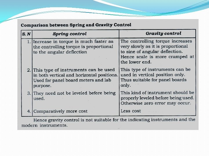
Spring control: Scale of spring control type instruments is uniform. Td α I, Also Tc α Ɵ At final deflection or steady state position: Tc = Td Therefore ƟαI
Gravity Control �In gravity controlled instruments, a small adjustable weight is attached to the spindle of the moving system such that the deflecting torque produced by the instrument has to act against the action of gravity. �Thus a controlling torque is obtained. This weight is called the control weight. Another adjustable weight is also attached is the moving system for zero adjustment and balancing purpose. This weight is called Balance weight.
Gravity Control (Diagram):
Gravity control: In this a small adjustable weight is attached to the moving system(pointer) in such a way that in deflection condition it produces a restoring or controlling torque. Weight W 1 provides the controlling torque, W 2 is for balancing the weight of the pointer. Tc = W 1 sinƟ x L =W 1 L sinƟ Thus Tc α sinƟ As Td α I At steady state position deflection torque=controlling torque Thus I α sinƟ The scale of the gravity control type instrunts is non uniform
DAMPING TORQUE �We have already seen that the moving system of the instrument will tend to move under the action of the deflecting torque. �But on account of the control torque, it will try to occupy a position of rest when the two torques are equal and opposite. �However, due to inertia of the moving system, the pointer will not come to rest immediately but oscillate about its final deflected position as shown in figure and takes appreciable time to come to steady state. �To overcome this difficulty a damping torque is to be developed by using a damping device attached to the moving system.
DAMPING TORQUE �The damping torque is proportional to the speed of rotation of the moving system, that is �Depending upon the degree of damping introduced in the moving system, the instrument may have any one of the following conditions as depicted in above graph.
DAMPING TORQUE 1. Under damped condition: The response is oscillatory 2. Over damped condition: The response is sluggish and it rises very slowly from its zero position to final position. 3. Critically damped condition: When the response settles quickly without any oscillation, the system is said to be critically damped. The damping torque is produced by the following methods: 1. Air Friction Damping 2. Fluid Friction Damping 3. Eddy Current Damping 4. Electromagnetic Damping
�Air friction or pneumatic damping:
Air Friction or Pneumatic Damping: �In this system a light aluminium piston is attached to the spindle of the instrument and is arranged to move in a fix air chamber closed at one end. The cross section of the chamber may be either circular or rectangular and the clearance between the piston and the side of the chamber is small and uniform. Compression and suction action of the piston on the air in the chamber damp the possible oscillations of moving system, because the motion of the piston in either direction is oppose by the air. �In second case a thin aluminium vane, mounted on the spindle, moves with very small clearance in a sector shaped box. Any tendency of the moving system to oscillate is damped by the action of the air on vane.
Eddy current damping:
Eddy current damping: �It is the most efficient type of the damping �In this a thin disc usually of copper or aluminium is mounted on the spindle. When this disc moves in the magnetic field of permanent magnet, line of force are cut and eddy current are set up in it. � The force that exists between these current and magnetic field is always in the direction opposing the motion and therefore, provide necessary damping. �The magnitude of the induce current and therefore of the damping force which is dependent on it, is directly proportional to the velocity of moving system.
Fluid friction damping:
TYPES OF AMMETERS & VOLTMETERS 1) Moving Iron Type Meters (AC & DC); a) Attraction type, b) Repulsion type. 2) Moving Coil Type Meters (AC & DC); a) Permanent Magnet type, b) Electrodynamic or Dynamometer. 3) Hot Wire Type (AC & DC); 4) Induction Type (AC & DC); a) Split phase, b) Shaded Pole type. 5) Electrostatic Type for Voltmeters Only;
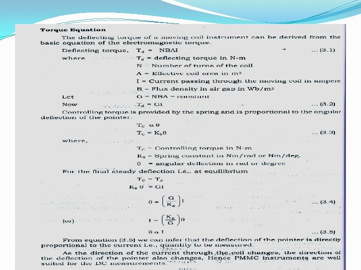
PMMC…………. �Principle of Operation: When a current carrying conductor is placed in a magnetic field, it experiences a force and tends to move in the direction as per Fleming’s left hand rule. Fleming left hand rule: If the first and the second finger and the thumb of the left hand are held so that they are at right angle to each other, then the thumb shows the direction of the force on the conductor, the first finger points towards the direction of the magnetic field and the second finger shows the direction of the current in the wire.
Construction: �A coil of thin wire is mounted on an aluminum frame (spindle) positioned between the poles of a U shaped permanent magnet which is made up of magnetic alloys like alnico. �The coil is pivoted on the jeweled bearing and thus the coil is free to rotate. The current is fed to the coil through spiral springs which are two in numbers. The coil which carries a current, which is to be measured, moves in a strong magnetic field produced by a permanent magnet and a pointer is attached to the spindle which shows the measured value.
PMMC instruments internal structure
PMMC INSTRUMENTS
Working: �When a current flow through the coil, it generates a magnetic field which is proportional to the current in case of an ammeter. The deflecting torque is produced by the electromagnetic action of the current in the coil and the magnetic field. �The controlling torque is provided by two phosphorous bronze flat coiled helical springs. These springs serve as a flexible connection to the coil conductors. �Damping is caused by the eddy current set up in the aluminum coil which prevents the oscillation of the coil.
Applications: The PMMC has a variety of uses. It can be used as: 1) Ammeter: �When PMMC is used as an ammeter, except for a very small current range, the moving coil is connected across a suitable low resistance shunt, so that only small part of the main current flows through the coil. �The shunt consists of a number of thin plates made up of alloy metal, which is usually magnetic and has a low temperature coefficient of resistance, fixed between two massive blocks of copper. A resistor of same alloy is also placed in series with the coil to reduce errors due to temperature variation.
ammeter
Applications………. . �Voltmeter: When PMMC is used as a voltmeter, the coil is connected in series with high resistance. Rest of the function is same as above. The same moving coil can be used as an ammeter or voltmeter with an interchange of above arrangement
Advantages: � The PMMC consumes less power and has great accuracy. � It has uniformly divided scale and can cover arc of 270 degree. � The PMMC has a high torque to weight ratio. � It can be modified as ammeter or voltmeter with suitable resistance. � It has efficient damping characteristics and is not affected by stray magnetic field. � It produces no losses due to hysteresis.
Disadvantage: �The moving coil instrument can only be used on D. C supply as the reversal of current produces reversal of torque on the coil. �It’s very delicate and sometimes uses ac circuit with a rectifier. �It’s costly as compared to moving coil iron instruments. �It may show error due to loss of magnetism of permanent magnet.
Moving Iron Instruments – Voltmeter and Ammeter Construction and basic principle operation of movingiron instruments Moving-iron instruments are generally used to measure alternating voltages and currents. In movingiron instruments the movable system consists of one or more pieces of specially-shaped soft iron, which are so pivoted as to be acted upon by the magnetic field produced by the current in coil. There are two general types of moving-iron instruments namely: 1. Repulsion (or double iron) type 2. Attraction (or single-iron) type
�Moving element: a small piece of soft iron in the form of a vane or rod. �Coil: to produce the magnetic field due to current flowing through it and also to magnetize the iron pieces. �In repulsion type, a fixed vane or rod is also used and magnetized with the same polarity. �Control torque is provided by spring or weight (gravity). �Damping torque is normally pneumatic, the damping device consisting of an air chamber and a moving vane attached to the instrument spindle. �Deflecting torque produces a movement on an aluminum pointer over a graduated scale.
Moving-iron instrument
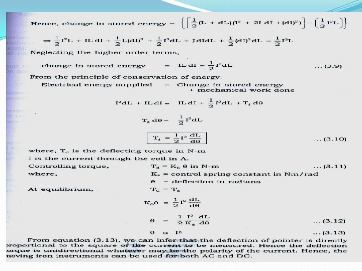
Working: The deflecting torque in any moving-iron instrument is due to forces on a small piece of magnetically ‘soft’ iron that is magnetized by a coil carrying the operating current. In repulsion type moving–iron instrument consists of two cylindrical soft iron vanes mounted within a fixed current-carrying coil. One iron vane is held fixed to the coil frame and other is free to rotate, carrying with it the pointer shaft. Two irons lie in the magnetic field produced by the coil that consists of only few turns if the instrument is an ammeter or of many turns if the instrument is a voltmeter.
Working: Current in the coil induces both vanes to become magnetized and repulsion between the similarly magnetized vanes produces a proportional rotation. The deflecting torque is proportional to the square of the current in the coil, making the instrument reading is a true ‘RMS’ quantity Rotation is opposed by a hairspring that produces the restoring torque. Only the fixed coil carries load current, and it is constructed so as to withstand high transient current. Moving iron instruments having scales that are nonlinear and somewhat crowded in the lower range of calibration
MOVING IRON INSTRUMENT
Application: Measurement of Electric Voltage and Current �Moving iron instruments are used as Voltmeter and Ammeter only. �Both can work on AC as well as on DC. Ammeter: �Instrument used to measure current in the circuit. �Always connected in series with the circuit and carries the current to be measured. �This current flowing through the coil produces the desired deflecting torque. �It should have low resistance as it is to be connected in series.
Application: Voltmeter �Instrument used to measure voltage between two points in a circuit. �Always connected in parallel. �Current flowing through the operating coil of the meter produces deflecting torque. �It should have high resistance. Thus a high resistance of order of kilo ohms is connected in series with the coil of the instrument
Advantages: �The instruments are suitable for use in AC and DC circuits. �The instruments are robust, owing to the simple construction of the moving parts. �The stationary parts of the instruments are also simple. �Instrument is low cost compared to moving coil instrument. �Torque/weight ratio is high, thus less frictional error.
Errors: �Error due to variation in temperature. �Error due to friction is quite small as torque-weight ratio is high in moving coil instruments. �Stray fields cause relatively low values of magnetizing force produced by the coil. Efficient magnetic screening is essential to reduce this effect. �Error due to variation of frequency causes change of reactance of the coil and also changes the eddy currents induced in neighbouring metal. �Deflecting torque is not exactly proportional to the square of the current due to non-linear characteristics of iron material.
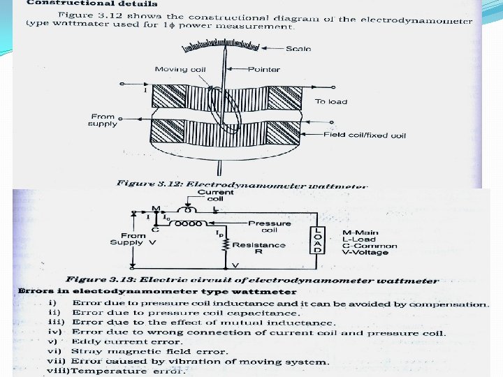
DYNAMOMETER �This instrument is suitable for the measurement of direct and alternating current, voltage and power. �The deflecting torque in dynamometer is relies by the interaction of magnetic field produced by a pair of fixed air cored coils and a third air cored coil capable of angular movement and suspended within the fixed coil.
DYNAMOMETER
INDUCTION TYPE INSTRUMENT � Such instruments are suitable for ac measurements only in these instruments the deflecting torque is produced by the eddy currents induced in an aluminum or copper disc or drum by the flux created by an electro-magnet. � The main advantages of such instruments are that (i) a full scale deflection can be obtained giving long and open scale (ii) the effect of stray magnetic field is small; (iii) damping is easier and effective.
INDUCTION TYPE INSTRUMENT These instruments have got some serious disadvantages (i) The greater deflection causes more stresses in the control springs. (ii) Variation in supply frequency and temperature may cause serious errors unless compensating device is employed. (iii) These instruments are costlier and consume more power � � Such instruments are mostly used as watt-meters or energy meters.
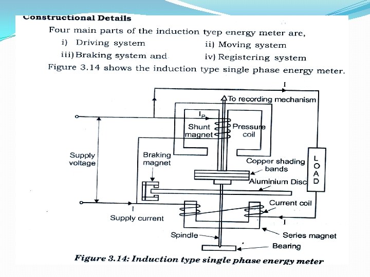
INDUCTION TYPE INSTRUMENT � � � Induction type wattmeter consists of two laminate electromagnets known as shunt electromagnet and series electromagnet respectively. Shunt magnet is excited by the current proportional to the voltage across load flowing through the pressure coil and series magnet is excited by the load current flowing through the current coil. A thin disc made of Cu or Al, pivoted at its centre, is placed between the shunt and series magnets so that it cuts the flux from both of the magnets.
INDUCTION TYPE INSTRUMENT � � � The deflection torque is produced by interaction of eddy current induced in the disc and the inducing flux in order to cause the resultant flux in shunt magnet to lag in phase by exactly 90° behind the applied voltage. One or more copper rings, known as copper shading bond are provided on one limb at the shunt magnet. Correct disappointed between shunt and series magnet fluxes may be attained by adjusting the position of copper shading bonds. The pressure coil circuit of induction type instrument is made as inductive as possible so that the flux of the shunt magnet may lag by 90° behind the applied voltage.