Lecture 13 Properties of Hardening Concrete Curing Cracking


 T conc = Concrete placement temperature at construction (o. F).")
 vs. Time ft = a log (t) + b")
 40 30 20 10 0 -10 -20 0 12 24 36 48")


 Maturity: Product of time")


 Strain time")
 sh Microstrain Basic creep (no drying) bc Loading and")


 Strain time")


- Slides: 44
Lecture #13 Properties of Hardening Concrete
Curing
Cracking Factors
Temperature and Evaporation
Thermal Stress Temperature change Coefficient of thermal expansion Concrete stiffness Cracking stress
Concrete Thermal Contraction T T set = = Coefficient of thermal expansion ~ 5*10 -6 /o. F = Difference in concrete temperature (T) and the concrete setting temperature (T set) = T set - T = Variation of the average concrete temperature after placement. Assume this variation tracks closely to the 24 -hour ambient air temperature cycle (after a 72 hour period). = 0. 95(T conc + TH)
Concrete Thermal Contraction (con’t) T conc = Concrete placement temperature at construction (o. F). Assume this value (approx. 80 o. F) = Change in concrete temperature due to heat of hydration = Hu = Total heat of hydration per gram (k. J/g) = 0. 007 (Tconc) – 3 x 10 -5 (Tconc)2 – 0. 0787 C = amount of cement (grams) per m 3 = Degree of hydration (estimate to be approximately 0. 15 -0. 2) cp = Specific heat of cement = 1. 044 k. J/g = Density of concrete ~ 2400 kg/m 3
Strength(ft) vs. Time ft = a log (t) + b
TEMPERATURE (C) 40 30 20 10 0 -10 -20 0 12 24 36 48 60 72 84 96 TIME (hours) FIGURE 1. The Nurse-Saul Maturity Function
S M, te
Maturity
Maturity Concepts Nurse - Saul Equation (units: Temp – Time) Maturity: Product of time & temperature To = Datum Temperature T = Average Concrete Temperature over Time “t” M = Maturity
ARRHENIUS EQUATIONS E = Activation Energy R = Gas Constant te = Equivalent Age or Time
LABORATORY TESTING FIELD MEASUREMENT Procedures for using maturity method involve laboratory testing and field measurements.
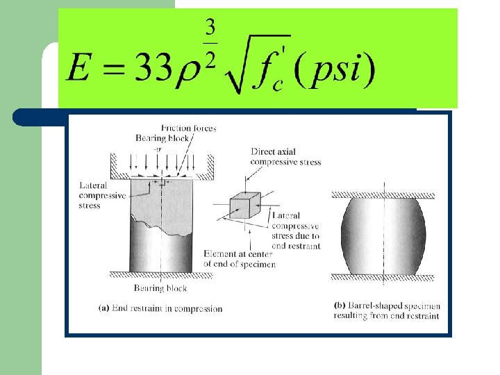
Elastic Modulus
Sawcut Timing and Depth
Curing
Strength Factors
Relative Humidity at ¾ inch
Effective Curing Thickness
Curing Quality Wind No Wind
Model of CSH Structure of CSH
Nature of Concrete Creep and Shrinkage
a Microstrain Elastic recovery Creep strain Elastic strain Creep recovery Irreversible creep Concrete unloaded Time after loading Typical creep curve for cement paste.
Burger Model Constant Stress (Creep) Strain time
b Free shrinkage (no load) sh Microstrain Basic creep (no drying) bc Loading and drying dc cr bc tot sh Time Creep of cement under simultaneous loading & drying. 62 =free shrinkage; =basic creep (specimen loaded but sh bc not drying); dc=drying creep; cr=total creep strain; tot=total strain (simultaneous loading & drying)
UPPER JACK PLATE LOAD BARS LOWER JACK PLATE UPPER LOAD PLATE 6 X 3 IN. PLUG (CONCRETE) C C C = 6 X 12 IN. TEST CYLINDERS C C C 6 X 3 IN. PLUG (CONCRETE) LOWER LOAD PLATE UPPER BASE PLATE SPRINGS LOWER BASE PLATE Spring-Loaded Creep Frame
Horizontal Mold for Creep Specimens
Cracking Frame
The Cracking Frame Test specimen T = 12 10 -6 K-1 strain gauge T = 1. 0 10 -6 K-1
Crack in Specimen
Preparation of Fracture Specimens
Determination of Creep where crp = Creep strain v = Shrinkage strain (ASTM C 157) e = Frame strain Fs = Force in concrete (F) Ec = Modulus of elasticity of concrete (F/L-2) Ac = Specimen cross sectional area (L 2)
Accumulative vs. Time
Burger Model Constant Stress (Creep) Strain time
Aggregate Effects
Effects of Paste Properties Effect of age of loading on the creep strain. Effect of w/c ratio on the shrinkage strain.
Mechanisms of Creep and Shrinkage • Creep It is a complex process involving slipping of surfaces past one another within the structure of C-S-H. It is a function of pore structure and ease of slippage of C-S-H particles. As the space between particles becomes less and less the degree of creep becomes less and less. • Drying Shrinkage Moisture loss is driven by the ambient relative humidity. As moisture escapes from the capillaries, menisci are created and capillary stresses are developed. As more moisture is evaporated, smaller and smaller menisci are created. This action creates stress and causes slippage between C-S-H particles.
ACI Committee 209 Method This method is based upon a method proposed by Branson and Christiason (2. 3) and was developed by ACI Committee 209 (2. 4) In 1982, ACI Special Publication 76 (2. 5) gives an updated but not significantly changed version of this method. This method uses the as the creep coefficient.
Shrinkage – ACI The shrinkage strain curing is at t days after the end of initial where = ultimate shrinkage strain = 415 to 1070 micro-strain = 0. 9 to 1. 10 and f = 20 to 130 days In the absence of specific data for local aggregate and conditions Committee 209 suggests that With = product of applicable correction factors The equations for the correction factors are given in Table A
Creep – ACI 209 The creep coefficient at t days after loading is given by where d = ultimate creep coefficient = 1. 30 to 4. 15 = 0. 40 to 0. 80 = 6 to 30 days In the absence of specific data for local aggregates and conditions Committee 209 suggests that where = product of applicable correction factors The equations for the correction factors are given in Table A
Strength and Modulus of Elasticity The concrete strength at t days is given by with suggested values of a = 4. 0 days = 0. 85 for most cured ordinary Portland cement concrete. The modulus of elasticity Ec at t days is given by which is often taken as when E and f’c are in MPa
Notes Creep Correction Factors Shrinkage Loading Age Relative Humidity Average Thickness Concrete Composition h=average thickness in mm 150 < h < 300 s= slump in mm c= cement content kg/m 3 1. 14 - 0. 00092 h for 1 st yr. of loading 1. 10 - 0. 00067 h ultimate value 0. 82 + 0. 00264 s 1. 23 - 0. 0015 h during 1 st year 1. 17 - 0. 0014 h ultimate value 0. 89 +. 00161 s 0. 75 +. 00061 c Table A ACI Creep and Shrinkage Correction Factors