Lec5 part 1 Packetizing Error Detection 1182022 1


")

is added")


 �Suppose you receive a binary bit word “ 0101” and you know")


 �Used for error checking �Unlike the parity check which is")
 �If the reminder “ 0” : data is correct �If")


")
")

, the available bandwidth is divided into")
, the stations share the bandwidth of")
, each station assigned a code")
- Slides: 44
Lec#5 part 1 Packetizing Error Detection 1/18/2022 1
The Data Link Layer �Data link layer is responsible for carrying a packet ( called frame) from one hop to the next hop. �Specific responsibilities of the data link layer include framing, addressing, flow control, error control, and media access control. 1/18/2022 2
Packetizing 1/18/2022 3
How Networks Send Data �To send data over a network, the data is broken down into small, manageable packets , each wrapped with the essential information needed to get it from its source to the correct destination. �In the sender, data is disassembled in small chunks. �Then it reassemble in the proper order when it reaches its destination. 1/18/2022 4
The Function of Packets in Network Communications �Networks cannot operate if computers put large amounts of data on the cable at the same time. 1/18/2022 5
The Function of Packets in Network Communications �There are two reasons why putting large chunks of data on the cable at one time slows down the network: 1. Large amounts of data sent as one large unit tie up the network and make timely interaction and communications impossible because one computer is flooding the cable with data. 2. The impact of retransmitting large units of data further multiplies network traffic. �These effects are minimized when the large data units are reformatted into smaller packages for better management of error correction in transmission. 1/18/2022 6
Components of Packets contents are based on the protocol used , but they basically contain: § Source address § Destination address § Data to be sent ( files & messages) § Other information like: § Giving instructions to the network on how to send data § Telling the receiving computer how to collect and arrange packets. § Checking data from errors (determine the need to resend the data) 1/18/2022 7
A Typical data packet on the Network error-checking component 1/18/2022 8
Error Detection 1/18/2022 9
Accuracy of the Transmitted Data �Data can be corrupted during transmission. �For reliable communication, errors must be detected and corrected. 1/18/2022 10
Single-Bit Error �In a single-bit error, only one bit in the data unit has changed. (0 → 1 or 1 → 0) 1/18/2022 11
Burst Error �Two or more bits in the data unit have changed �Burst error does not necessarily mean that the errors occur in consecutive bits Corrupted Bits = 4 bits 1/18/2022 12
Error Detection �Error detection uses the concept of redundancy, which means adding extra (redundant) bits for detecting errors at the destination 1/18/2022 13
Error Detection Methods Three types of redundancy checks: Error Detection Methods Parity Check 1/18/2022 Cycle Redundancy Checksum 14
Parity Check �The most common and least expensive �a parity bit (extra bit)is added to every data unit so that the total number of 1’s is even or odd. �Simple parity check can detect single bit errors. �It can detect burst errors only if the total number of errors in each data unit is odd. 1/18/2022 15
Even/odd parity �Computers can sometimes make errors when they transmit data. �Even/odd parity: �is basic method for detecting if an odd number of bits has been switched by accident. � Odd parity: � The number of 1 -bit must add up to an odd number � Even parity: � The number of 1 -bit must add up to an even number 1/18/2022 16
Even/odd parity �The computer knows which parity it is using �If it uses an even parity: �If the number of of 1 -bit add up to an odd number then it knows there was an error: �If it uses an odd: �If the number of of 1 -bit add up to an even number then it knows there was an error: �However, If an even number of 1 -bit is flipped the parity will still be the same. But an error occurs �The even/parity can’t this detect this error. 1/18/2022 17
Even/odd parity �It is useful when an odd number of 1 -bits is flipped. �Suppose we have an 7 -bit binary word (7 -digits). �If you need to change the parity you need to add 1 (parity bit) to the binary word. �You now have 8 digit word. �However, the computer knows that the added bit is a parity bit and therefore ignore it. 1/18/2022 18
Example (1) �Suppose you receive a binary bit word “ 0101” and you know you are using an odd parity. �Is the binary word errored? �The answer is yes: � There are 2 1 -bit, which is an even number � We are using an odd parity � So there must have an error. 1/18/2022 19
Parity Bit �A single bit is appended to each data chunk �makes the number of 1 bits even/odd �Example: even parity � 1000000(1) � 1111101(0) � 1001001(1) �Example: odd parity � 1000000(0) � 1111101(1) � 1001001(0) 1/18/2022 20
Parity Checking �Assume we are using even parity with 7 -bit ASCII. �The letter V in 7 -bit ASCII is encoded as 0110101. �How will the letter V be transmitted? �Because there are four 1 s (an even number), parity is set to zero. �This would be transmitted as: 01101010. �If we are using an odd parity: �The letter V will be transmitted as 1/18/2022 01101011 21
Exercise 1 �Suppose you are using an odd parity. What should the binary word “ 1010” look like after you add the parity bit? �Answer: �There is an even number of 1 -bits. � So we need to add another 1 -bit �Our new word will look like “ 10101”. 1/18/2022 22
Exercise 2 �Suppose you are using an even parity. What should the binary word “ 1010” look like after you add a parity bit? �Answer: �There is an even number of 1’s. � So we need to add another 0 �Our new word will look like “ 10100”. 1/18/2022 23
Parity Check Sender 0 0 1 Receiver 0 1 0 0 1 Data Reject Data No 0 1 Even? Yes , Drop parity bit & accept data Calculate Parity bit Count bits 0 0 1 0 1 0 1 1 Data + Redundancy Bits The Medium 1/18/2022 24
Cyclic Redundancy Check (CRC) �Used for error checking �Unlike the parity check which is based on addition, CRC is based on binary division. �Before sending data , some calculation are done on the data packets to generate a CRC number �The CRC is calculated so the packet ( data + CRC ) becomes exactly divisible by a predetermined number. �When data is received , the packet is divided by the number. 1/18/2022 25
Cyclic Redundancy Check (CRC) �If the reminder “ 0” : data is correct �If the reminder “ 1” : data has a problem and need to be sent again. �CRC Can detect single bit & burst errors. 1/18/2022 26
Checksum �Uses a process known as checksum to generate an error-detection character appended to the data. �This calculation is applied in both the sender side and the receiver side �A match between receiver checksum and transmitted checksum indicates good data. �A mismatch indicates an error has occurred. �Capable of detecting single or burst errors. �It is simple to implement in either hardware or software. 1/18/2022 27
Lec#5 part 2 Multiple Access Methods
Multiple Access Methods
Multiple Access Methods �When nodes or stations are connected and use a common link (cable or air) , called a multipoint or broadcast link, we need a multiple-access protocol to coordinate access to the link. �It is a set of rules that defines how a stations puts data onto the link and takes data from the link.
Multiple Access Methods �Many formal protocols have been devised to handle access to a shared links. We categorize them into three groups. Multiple Access Protocols Controlled Access Protocol Ex: Polling and Token passing Random Access protocols Channelization protocol Ex: CSMA/CD and CSMA/CA Ex: FDMA, TDMA, and CDMA
CONTROLLED ACCESS �In controlled access, the stations consult one another to find which station has the right to send. �A station cannot send unless it has been authorized by other stations. Two methods: 1. Polling Access Method 2. Token Passing Access Method
1 Polling Access Method �In this access method, one station is designated as the primary device and the others are secondary stations. �All access to the network is controlled by the primary station. �The primary queries (polls) each of the secondary stations in turn, if it has information to be transmitted. �Only when it is polled does the secondary have access to the communication channel.
2 Token-Passing Access Method �In this access method, a special type of packet, called a token, circulates around a cable ring from station to station. � When any station on the ring needs to send data across the network, it must wait for a free token. �When a free token is detected, the station will take control of it if the station has data to send.
Random Access Methods �In random access or contention methods, no station is superior to another station and none is assigned the control over another (i. e. each station has the right to the medium without being controlled by any other station). �It is named contention method because stations on the network contend, or compete, for an opportunity to send data. �Methods: 1. 2. Carrier-Sense Multiple Access With Collision Detection Carrier-Sense Multiple Access With Collision Avoidance
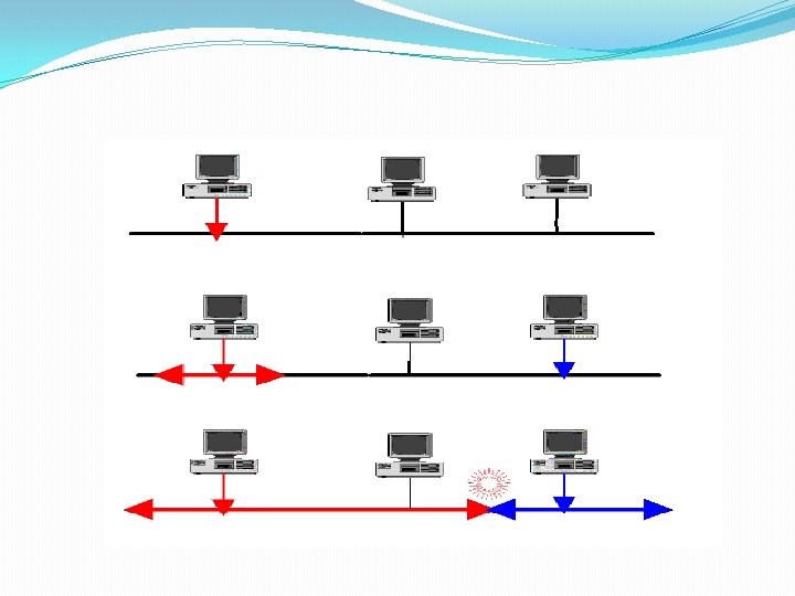
Carrier-Sense Multiple Access � In this way of methods, each station first listen to the cable (or check the state of the cable ) before sending. � When the station "senses" that the cable is free ( that there is no traffic on the cable) it can send a frame. � Once the station has transmitted frame on the cable, no other station can transmit data until the original data has reached its destination and the cable is free again.
Collisions �Even though each station listens for network traffic before it attempts to transmit, an access conflict -collision- will happen if more than one station tries to send at the same time. �When a collision happened, the frames will be either destroyed or modified �The collisions occur because it takes time for signals to propagate through the link. �Two specialized methods of collision management have been developed to improve performance: Collision Detection (CD) and Collision Avoidance (CA).
Carrier-Sense Multiple Access With Collision Detection �The carrier-sense multiple access with collision detection (CSMA/CD) adds a procedure to handle a collision. �In this method, a station monitors the medium after it sends a frame to see if the transmission was successful. If so, the station is finished. If, however, there is a collision, the frame is sent again. �In the case of collision, the two stations involved stop transmitting for a random period of time and then attempt to retransmit. �Each station determines its own waiting period; this reduces the chance that the computers will once again transmit simultaneously.
Carrier-Sense Multiple Access With Collision Avoidance �The Carrier-Sense Multiple Access With Collision Avoidance (CSMA/CA) differs from the previous method in that there is no collision. �Each station signals its intent to transmit before it actually transmits data.
CHANNELIZATION �Channelization is a multiple-access method in which the available bandwidth of a link is shared in time, frequency, or through code, between different stations. �Used for wireless communications. �Methods: 1. Frequency division Multiple Access 2. Time division Multiple Access 3. Code division Multiple Access
Frequency-Division Multiple Access �In frequency-division multiple access (FDMA), the available bandwidth is divided into frequency bands. �Each station is allocated a band to send its data. In other words, each band is reserved for a specific station, and it belongs to the station all the time.
Time-division Multiple Access �In time-division multiple access (TDMA), the stations share the bandwidth of the channel in time. �Each station is allocated a time slot during which it can send data. �Each station transmits data in is assigned time slot.
Code-Division Multiple Access �In the code-division multiple access (CDMA), each station assigned a code that used to send its data. �Several transmitters can send information simultaneously over a single communication channel. �CDMA differs from FDMA because only one channel occupies the entire bandwidth of the link. �It differs from TDMA because all stations can send data simultaneously; there is no timesharing.