LCLS Undulator Magnetic Measurements Zack Wolf Scott Anderson


- Slides: 30
LCLS Undulator Magnetic Measurements Zack Wolf, Scott Anderson, Ralph Colon, Brendan Dix, Scott Jansson, Dave Jensen, Luis Juarez, Seva Kaplounenko, Yurii Levashov, Wei Wang, Achim Weidemann April 11, 2006 Undulator Magnetic Measurements Zack Wolf wolf@slac. stanford. edu
Undulator Tuning, General Approach § Use ANL and DESY experience § Techniques have been developed at ANL and DESY which work very well. § We will use the best of the ANL and DESY measurement techniques as our starting point (both have been very generous in sharing with us). § We need to adapt for production measurements. April 11, 2006 Undulator Magnetic Measurements Zack Wolf wolf@slac. stanford. edu
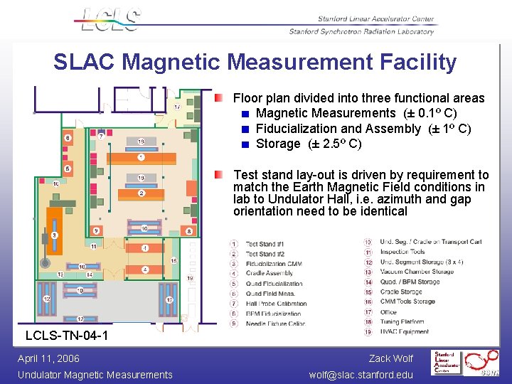
SLAC Magnetic Measurement Facility Floor plan divided into three functional areas Magnetic Measurements (± 0. 1º C) Fiducialization and Assembly (± 1º C) Storage (± 2. 5º C) Test stand lay-out is driven by requirement to match the Earth Magnetic Field conditions in lab to Undulator Hall, i. e. azimuth and gap orientation need to be identical LCLS-TN-04 -1 April 11, 2006 Undulator Magnetic Measurements Zack Wolf wolf@slac. stanford. edu
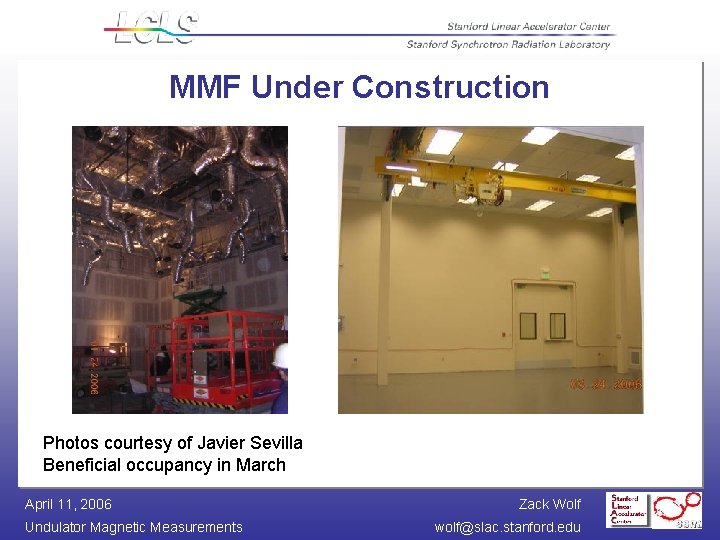
MMF Under Construction Photos courtesy of Javier Sevilla Beneficial occupancy in March April 11, 2006 Undulator Magnetic Measurements Zack Wolf wolf@slac. stanford. edu
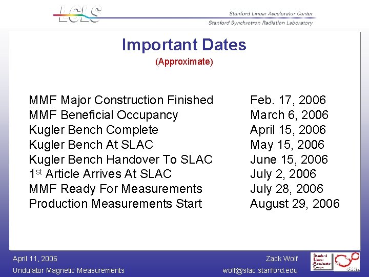
Important Dates (Approximate) MMF Major Construction Finished MMF Beneficial Occupancy Kugler Bench Complete Kugler Bench At SLAC Kugler Bench Handover To SLAC 1 st Article Arrives At SLAC MMF Ready For Measurements Production Measurements Start April 11, 2006 Undulator Magnetic Measurements Feb. 17, 2006 March 6, 2006 April 15, 2006 May 15, 2006 June 15, 2006 July 28, 2006 August 29, 2006 Zack Wolf wolf@slac. stanford. edu
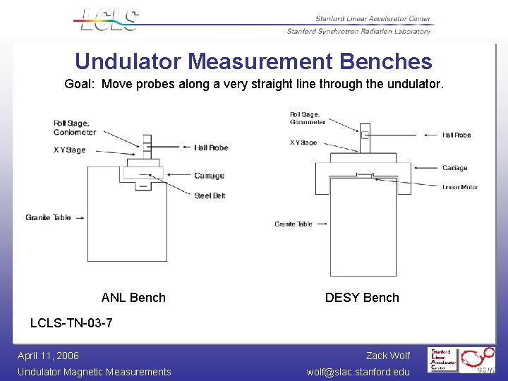
Undulator Measurement Benches Goal: Move probes along a very straight line through the undulator. ANL Bench DESY Bench LCLS-TN-03 -7 April 11, 2006 Undulator Magnetic Measurements Zack Wolf wolf@slac. stanford. edu
Kugler Bench On order, expected at SLAC May 15, 2006. Ready for use June 15, 2006. April 11, 2006 Undulator Magnetic Measurements Zack Wolf wolf@slac. stanford. edu
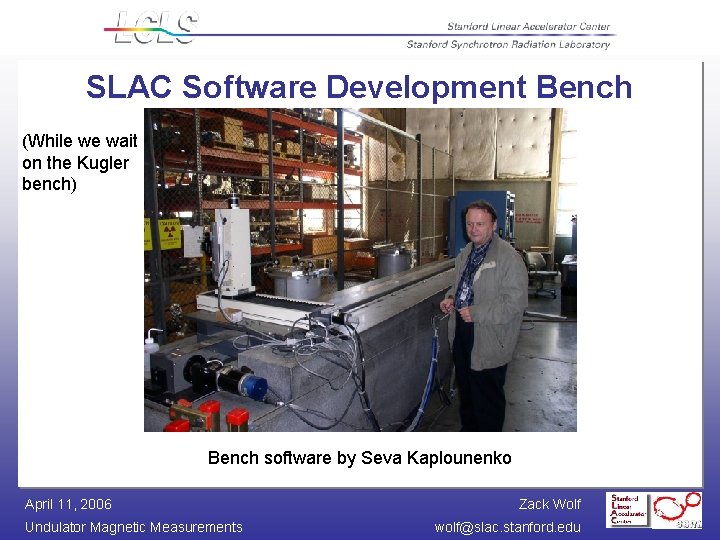
SLAC Software Development Bench (While we wait on the Kugler bench) Bench software by Seva Kaplounenko April 11, 2006 Undulator Magnetic Measurements Zack Wolf wolf@slac. stanford. edu
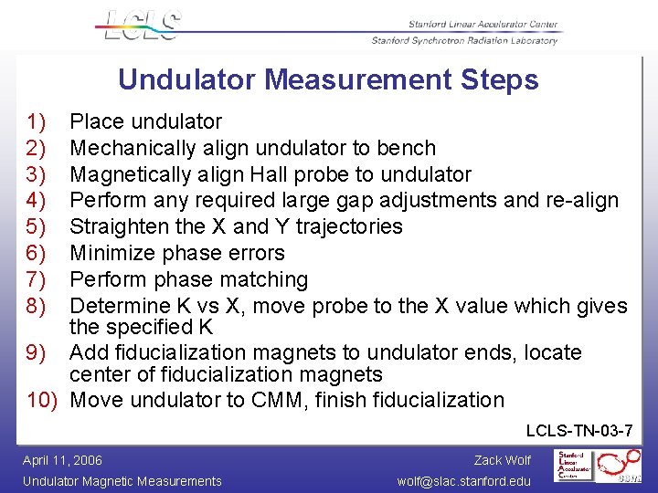
Undulator Measurement Steps 1) 2) 3) 4) 5) 6) 7) 8) Place undulator Mechanically align undulator to bench Magnetically align Hall probe to undulator Perform any required large gap adjustments and re-align Straighten the X and Y trajectories Minimize phase errors Perform phase matching Determine K vs X, move probe to the X value which gives the specified K 9) Add fiducialization magnets to undulator ends, locate center of fiducialization magnets 10) Move undulator to CMM, finish fiducialization LCLS-TN-03 -7 April 11, 2006 Undulator Magnetic Measurements Zack Wolf wolf@slac. stanford. edu
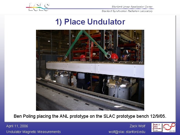
1) Place Undulator Ben Poling placing the ANL prototype on the SLAC prototype bench 12/9/05. April 11, 2006 Undulator Magnetic Measurements Zack Wolf wolf@slac. stanford. edu
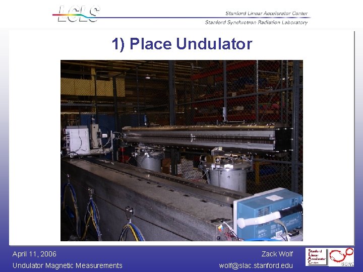
1) Place Undulator April 11, 2006 Undulator Magnetic Measurements Zack Wolf wolf@slac. stanford. edu
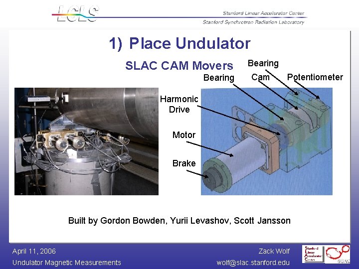
1) Place Undulator SLAC CAM Movers Bearing Cam Potentiometer Harmonic Drive Motor Brake Built by Gordon Bowden, Yurii Levashov, Scott Jansson April 11, 2006 Undulator Magnetic Measurements Zack Wolf wolf@slac. stanford. edu
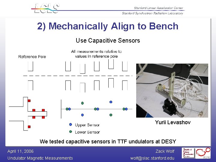
2) Mechanically Align to Bench Use Capacitive Sensors Yurii Levashov We tested capacitive sensors in TTF undulators at DESY April 11, 2006 Undulator Magnetic Measurements Zack Wolf wolf@slac. stanford. edu
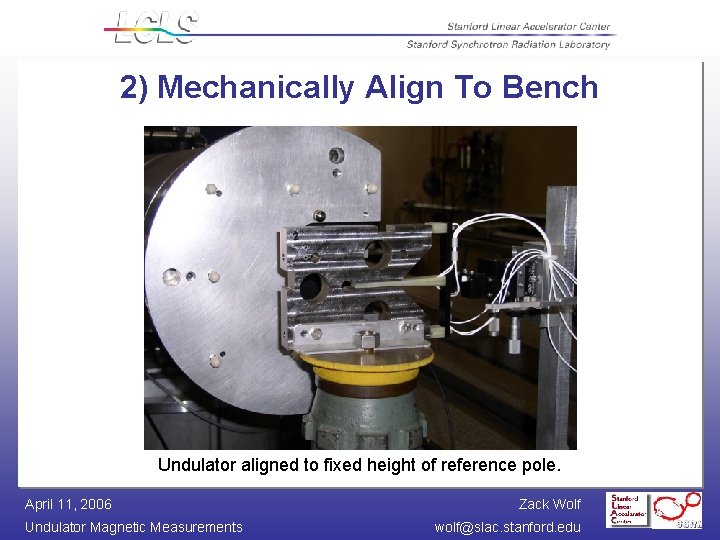
2) Mechanically Align To Bench Undulator aligned to fixed height of reference pole. April 11, 2006 Undulator Magnetic Measurements Zack Wolf wolf@slac. stanford. edu
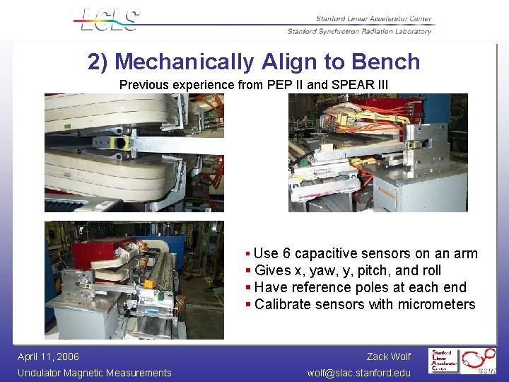
2) Mechanically Align to Bench Previous experience from PEP II and SPEAR III § Use 6 capacitive sensors on an arm § Gives x, yaw, y, pitch, and roll § Have reference poles at each end § Calibrate sensors with micrometers April 11, 2006 Undulator Magnetic Measurements Zack Wolf wolf@slac. stanford. edu
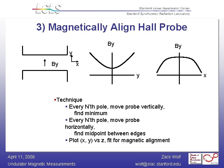
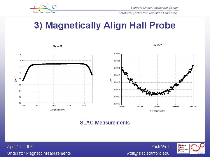
3) Magnetically Align Hall Probe By By x y x §Technique § Every N’th pole, move probe vertically, find minimum § Every N’th pole, move probe horizontally, find midpoint between edges § Plot (x, y) vs z, fit for magnetic alignment April 11, 2006 Undulator Magnetic Measurements Zack Wolf wolf@slac. stanford. edu
3) Magnetically Align Hall Probe SLAC Measurements April 11, 2006 Undulator Magnetic Measurements Zack Wolf wolf@slac. stanford. edu
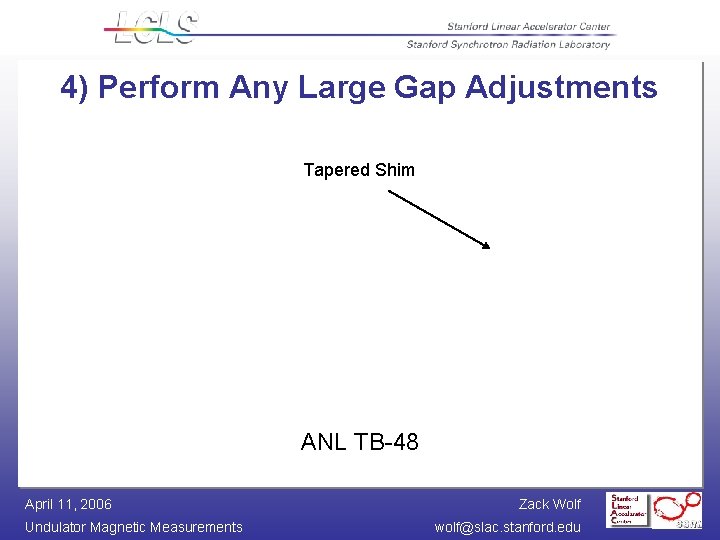
4) Perform Any Large Gap Adjustments Tapered Shim ANL TB-48 April 11, 2006 Undulator Magnetic Measurements Zack Wolf wolf@slac. stanford. edu
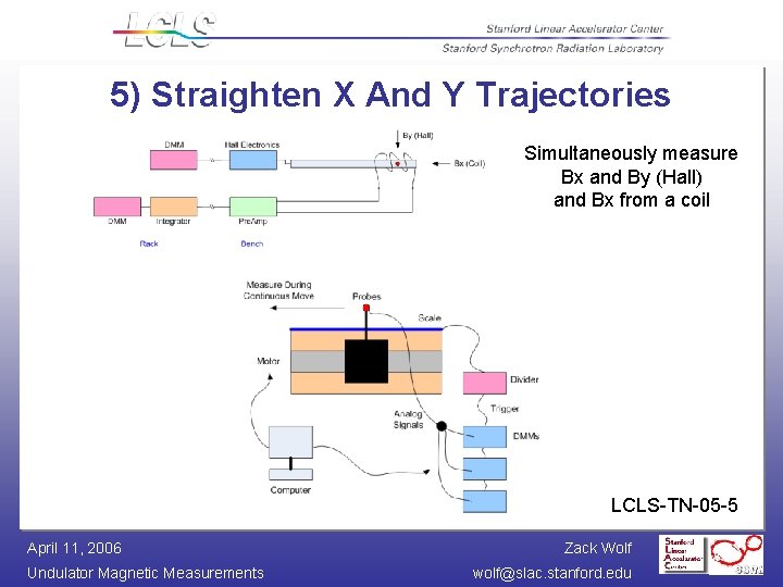
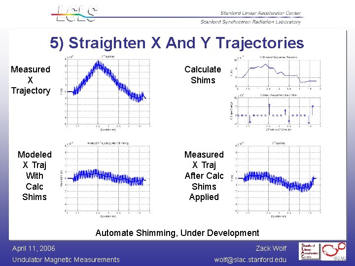
5) Straighten X And Y Trajectories Simultaneously measure Bx and By (Hall) and Bx from a coil LCLS-TN-05 -5 April 11, 2006 Undulator Magnetic Measurements Zack Wolf wolf@slac. stanford. edu
5) Straighten X And Y Trajectories Isaac Vasserman’s Ideas ANL/APS/TB-48 § Apply shims to top and bottom poles § Shims weaken By, don’t cause Bx § Can’t strengthen pole, instead place shims on next pole to reduce deflection in other direction LCLS-TN-04 -7 April 11, 2006 Undulator Magnetic Measurements § Developing software to try to automate shim placement Zack Wolf wolf@slac. stanford. edu
5) Straighten X And Y Trajectories Measured X Trajectory Calculate Shims Modeled X Traj With Calc Shims Measured X Traj After Calc Shims Applied Automate Shimming, Under Development April 11, 2006 Undulator Magnetic Measurements Zack Wolf wolf@slac. stanford. edu
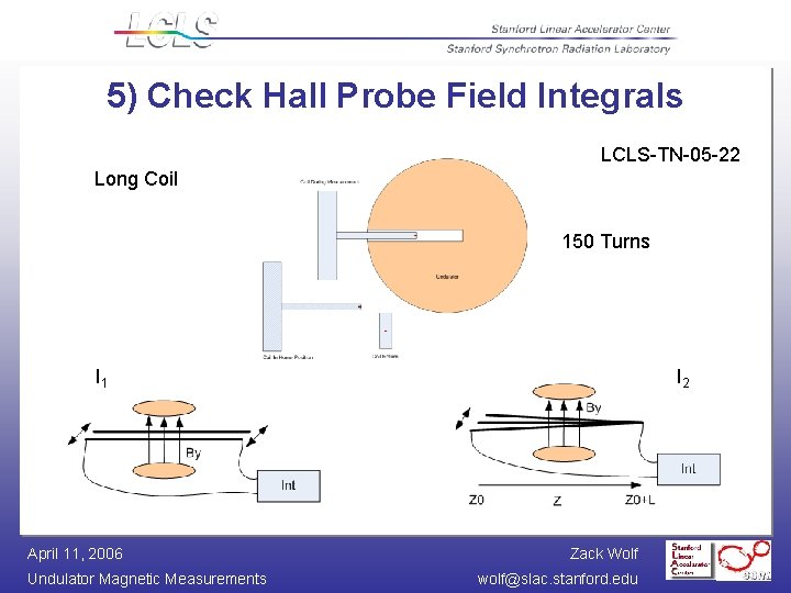
5) Check Hall Probe Field Integrals LCLS-TN-05 -22 Long Coil 150 Turns I 1 April 11, 2006 Undulator Magnetic Measurements I 2 Zack Wolf wolf@slac. stanford. edu
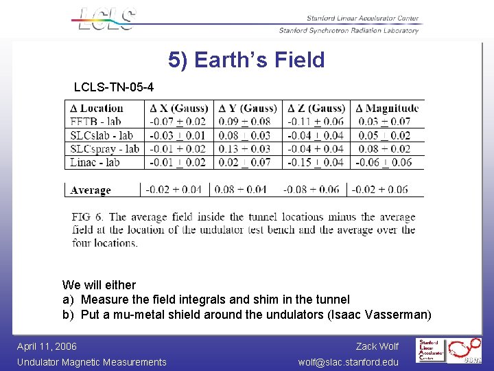
5) Earth’s Field LCLS-TN-05 -4 We will either a) Measure the field integrals and shim in the tunnel b) Put a mu-metal shield around the undulators (Isaac Vasserman) April 11, 2006 Undulator Magnetic Measurements Zack Wolf wolf@slac. stanford. edu
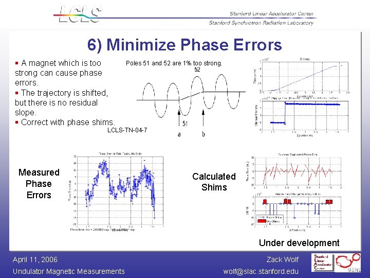
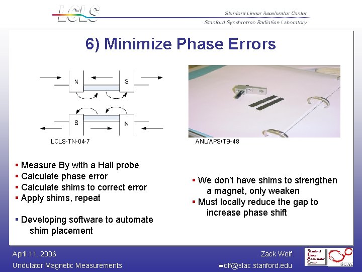
6) Minimize Phase Errors § A magnet which is too strong can cause phase errors. § The trajectory is shifted, but there is no residual slope. § Correct with phase shims. Poles 51 and 52 are 1% too strong. LCLS-TN-04 -7 Measured Phase Errors Calculated Shims Under development April 11, 2006 Undulator Magnetic Measurements Zack Wolf wolf@slac. stanford. edu
6) Minimize Phase Errors LCLS-TN-04 -7 § Measure By with a Hall probe § Calculate phase error § Calculate shims to correct error § Apply shims, repeat § Developing software to automate shim placement April 11, 2006 Undulator Magnetic Measurements ANL/APS/TB-48 § We don’t have shims to strengthen a magnet, only weaken § Must locally reduce the gap to increase phase shift Zack Wolf wolf@slac. stanford. edu
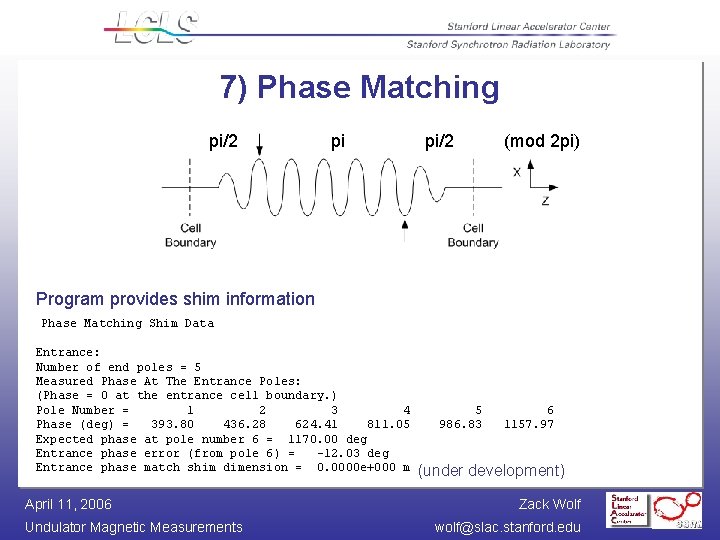
7) Phase Matching pi/2 pi pi/2 (mod 2 pi) Program provides shim information Phase Matching Shim Data Entrance: Number of end poles = 5 Measured Phase At The Entrance Poles: (Phase = 0 at the entrance cell boundary. ) Pole Number = 1 2 3 4 Phase (deg) = 393. 80 436. 28 624. 41 811. 05 Expected phase at pole number 6 = 1170. 00 deg Entrance phase error (from pole 6) = -12. 03 deg Entrance phase match shim dimension = 0. 0000 e+000 m April 11, 2006 Undulator Magnetic Measurements 5 986. 83 6 1157. 97 (under development) Zack Wolf wolf@slac. stanford. edu
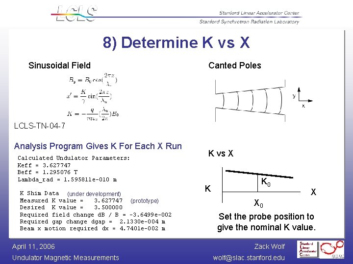
8) Determine K vs X Sinusoidal Field Canted Poles LCLS-TN-04 -7 Analysis Program Gives K For Each X Run Calculated Undulator Parameters: Keff = 3. 627747 Beff = 1. 295076 T Lambda_rad = 1. 595811 e-010 m K Shim Data (under development) Measured K value = 3. 627747 (prototype) Desired K value = 3. 500000 Required field change d. B / B = -3. 6499 e-002 Required gap change dgap = 2. 1330 e-004 m Beam x motion required dx = 4. 7401 e-002 m April 11, 2006 Undulator Magnetic Measurements K vs X K K 0 X X 0 Set the probe position to give the nominal K value. Zack Wolf wolf@slac. stanford. edu
9) Add Fiducialization Magnets Need to relate magnetic field to tooling balls. Yurii Levashov Attach to undulator ends, measure offsets LCLS-TN-05 -10 April 11, 2006 Undulator Magnetic Measurements Zack Wolf wolf@slac. stanford. edu
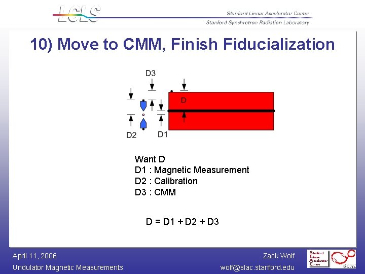
10) Move to CMM, Finish Fiducialization Want D D 1 : Magnetic Measurement D 2 : Calibration D 3 : CMM D = D 1 + D 2 + D 3 April 11, 2006 Undulator Magnetic Measurements Zack Wolf wolf@slac. stanford. edu
Conclusion • Our group’s next big magnetic measurement project is the LCLS. • A new magnetic measurements lab is being built. • We will use Hall probes and coils to tune the undulators. • Long coils will check the first and second field integrals. • High gradient magnets with well defined centers will be used to fiducialize the undulators. • Algorithms are being developed to automate shimming. April 11, 2006 Undulator Magnetic Measurements Zack Wolf wolf@slac. stanford. edu