
Linac Coherent Light Source Vacuum Systems Karen Fant

- Slides: 42
Linac Coherent Light Source Vacuum Systems Karen Fant Mechanical Engineering and Technical Support Division Director Accelerator Directorate 7/12/2011
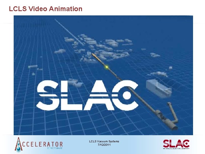
LCLS Video Animation LCLS Vacuum Systems 7/12/2011
Overview of LCLS Vacuum • Systems: – Injector (RF Gun and Cathode; Vacuum Controls) – Linac (Beam Switch Yard) – Undulator Area (Beam Transport Hall; Undulator Vacuum Chamber; Beam Dump; X-Ray Front End Enclosure) – Photon Area (Coherent X-ray Imaging Instrument; Matter in Extreme Conditions Instrument) • Combination of old and new vacuum systems • Utilizes various technologies – Pumping schemes include roughing, diffusion, turbo, cryo, sputter ion, differential • Spans pressure ranges from 1 x 10 -4 to 1 x 10 -10 Torr – Multiple places where high pressure regions are adjacent to low pressure regions – Challenges of contamination from higher pressure regions LCLS Vacuum Systems 7/12/2011
Vacuum Specifications Generated Early • Design reviews required – Outgassing rate assumptions, conductance calculations, pumping speed requirements, pump spacing calculations, pressure profiles, list of materials and hardware, compatibility with SLAC UHV requirements, RGA scans is available • Fabrication and cleaning to SLAC UHV specifications or approved deviation • Post processing bake to 200 C • RGA scans – No peak over 5 x 10 -12 Torr for mass>44 & total peaks >44 <5 x 10 -11 Torr • Leak Detection – He immersion >1 minute with minimum sensitivity 2 x 10 -10 std cc/sec • Recommended UHV hardware – Noble diode ion pump, VAT gate valves, MKS or GP gauges, dry fore-pump, conflat flanges LCLS Vacuum Systems 7/12/2011
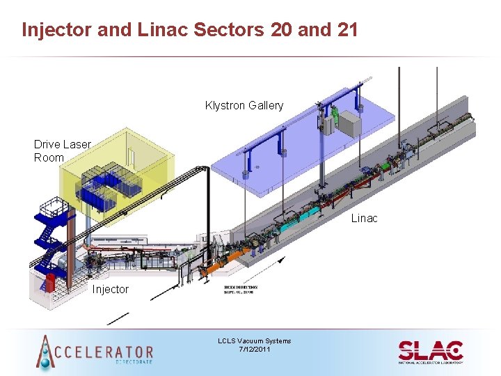
Injector and Linac Sectors 20 and 21 Klystron Gallery Drive Laser Room Linac Injector LCLS Vacuum Systems 7/12/2011
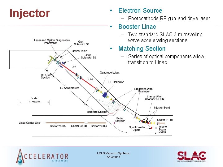
Injector • Electron Source – Photocathode RF gun and drive laser • Booster Linac – Two standard SLAC 3 -m traveling wave accelerating sections • Matching Section – Series of optical components allow transition to Linac LCLS Vacuum Systems 7/12/2011
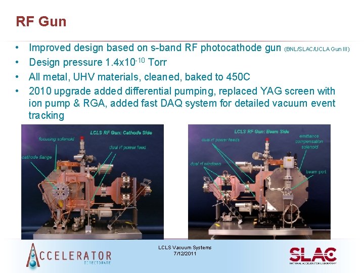
RF Gun • • Improved design based on s-band RF photocathode gun (BNL/SLAC/UCLA Gun III) Design pressure 1. 4 x 10 -10 Torr All metal, UHV materials, cleaned, baked to 450 C 2010 upgrade added differential pumping, replaced YAG screen with ion pump & RGA, added fast DAQ system for detailed vacuum event tracking LCLS Vacuum Systems 7/12/2011
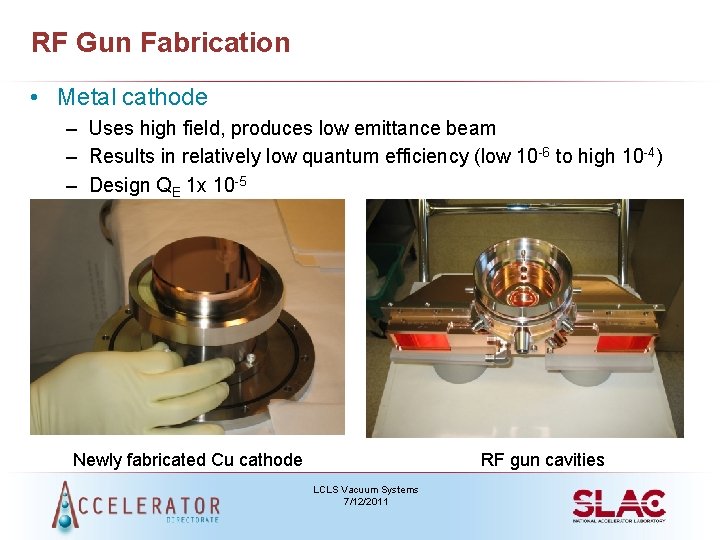
RF Gun Fabrication • Metal cathode – Uses high field, produces low emittance beam – Results in relatively low quantum efficiency (low 10 -6 to high 10 -4) – Design QE 1 x 10 -5 Newly fabricated Cu cathode RF gun cavities LCLS Vacuum Systems 7/12/2011
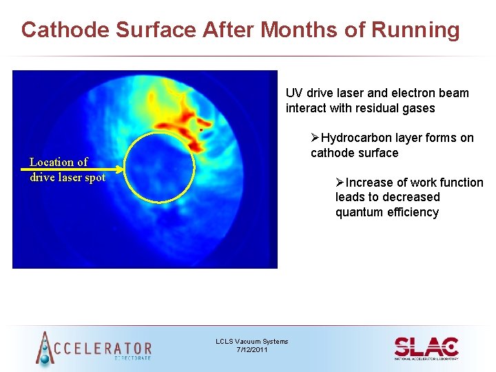
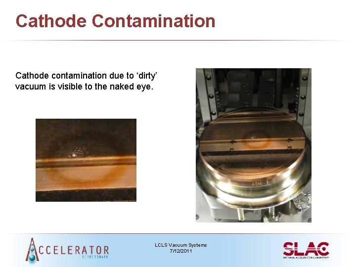
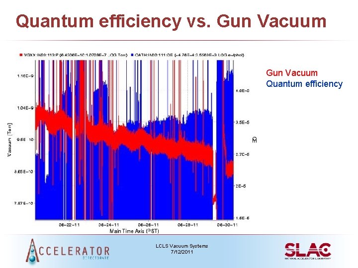
Cathode Surface After Months of Running UV drive laser and electron beam interact with residual gases ØHydrocarbon layer forms on cathode surface Location of drive laser spot ØIncrease of work function leads to decreased quantum efficiency LCLS Vacuum Systems 7/12/2011
Cathode Contamination Cathode contamination due to ‘dirty’ vacuum is visible to the naked eye. LCLS Vacuum Systems 7/12/2011
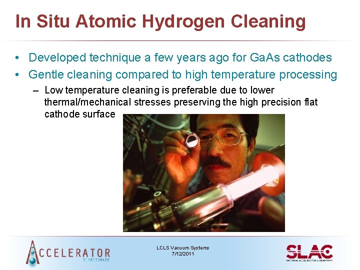
In Situ Atomic Hydrogen Cleaning • Developed technique a few years ago for Ga. As cathodes • Gentle cleaning compared to high temperature processing – Low temperature cleaning is preferable due to lower thermal/mechanical stresses preserving the high precision flat cathode surface LCLS Vacuum Systems 7/12/2011
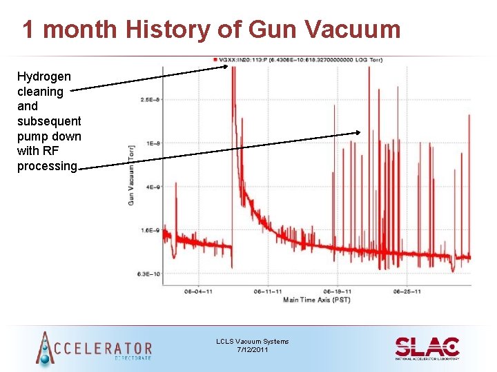
1 month History of Gun Vacuum Hydrogen cleaning and subsequent pump down with RF processing LCLS Vacuum Systems 7/12/2011
Quantum efficiency vs. Gun Vacuum Quantum efficiency LCLS Vacuum Systems 7/12/2011
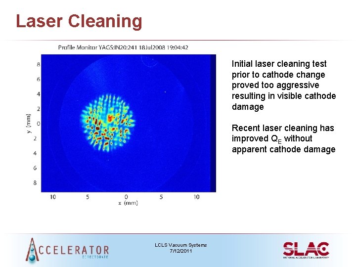
Laser Cleaning Initial laser cleaning test prior to cathode change proved too aggressive resulting in visible cathode damage Recent laser cleaning has improved QE without apparent cathode damage LCLS Vacuum Systems 7/12/2011
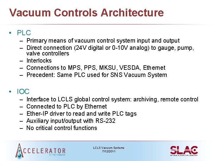
Vacuum Controls Architecture • PLC – Primary means of vacuum control system input and output – Direct connection (24 V digital or 0 -10 V analog) to gauge, pump, valve controllers – Interlocks – Connections to MPS, PPS, MKSU, VESDA, Ethernet – Precedent: Same PLC used for SNS Vacuum System • IOC – – – Interface to LCLS global control system: archiving, remote control Connected to PLC by Ethernet Ether-IP driver to read and write PLC tags Auxiliary input/output with RS-232 No critical control functions LCLS Vacuum Systems 7/12/2011
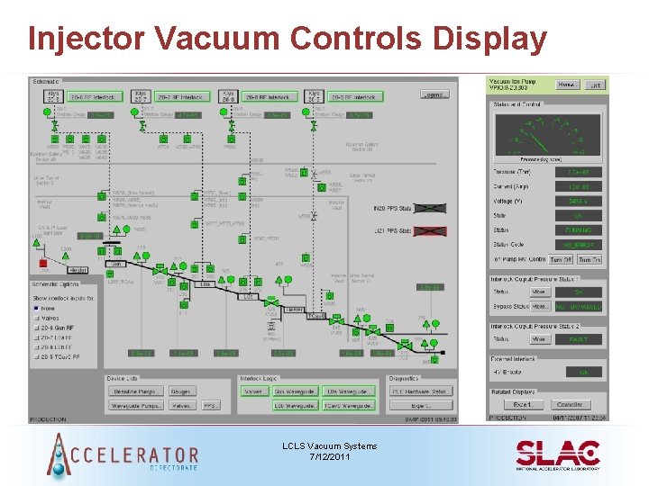
Injector Vacuum Controls Display LCLS Vacuum Systems 7/12/2011
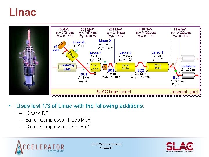
Linac • Uses last 1/3 of Linac with the following additions: – X-band RF – Bunch Compressor 1: 250 Me. V – Bunch Compressor 2: 4. 3 Ge. V LCLS Vacuum Systems 7/12/2011
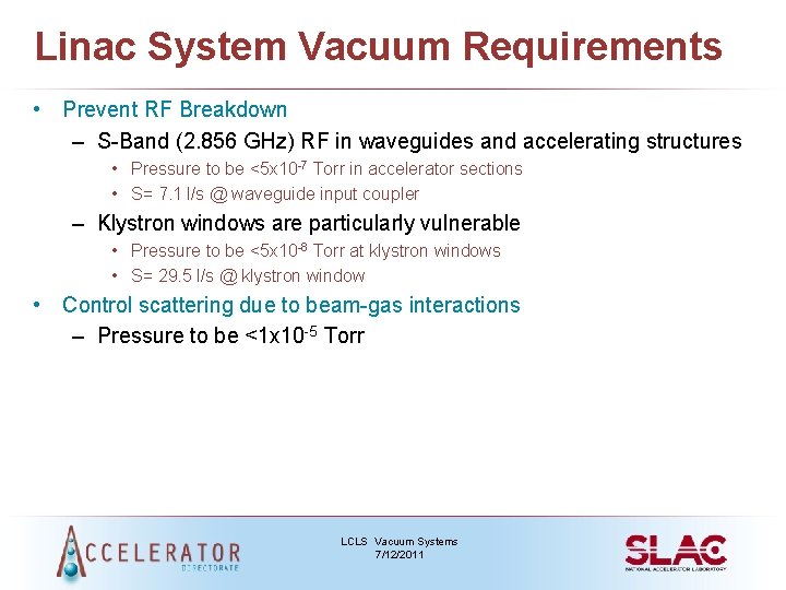
Linac System Vacuum Requirements • Prevent RF Breakdown – S-Band (2. 856 GHz) RF in waveguides and accelerating structures • Pressure to be <5 x 10 -7 Torr in accelerator sections • S= 7. 1 l/s @ waveguide input coupler – Klystron windows are particularly vulnerable • Pressure to be <5 x 10 -8 Torr at klystron windows • S= 29. 5 l/s @ klystron window • Control scattering due to beam-gas interactions – Pressure to be <1 x 10 -5 Torr LCLS Vacuum Systems 7/12/2011
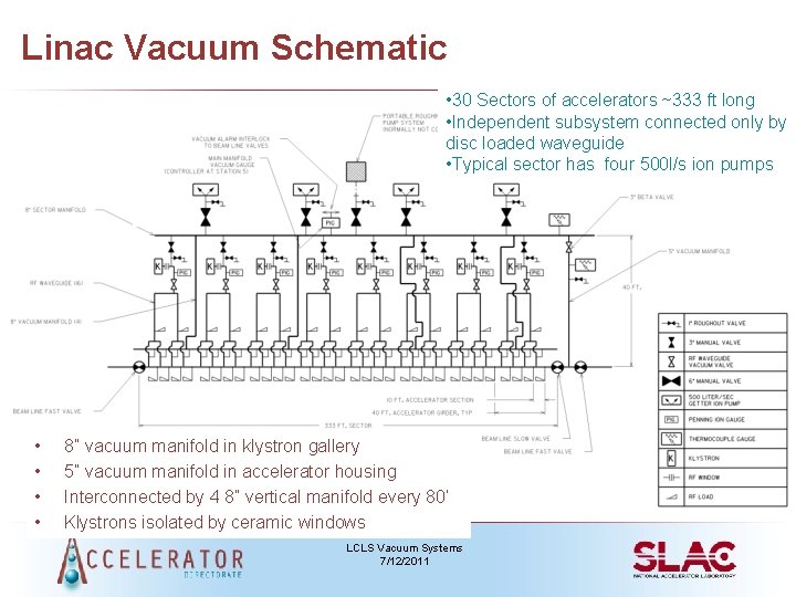
Linac Vacuum Schematic • 30 Sectors of accelerators ~333 ft long • Independent subsystem connected only by disc loaded waveguide • Typical sector has four 500 l/s ion pumps • • 8” vacuum manifold in klystron gallery 5” vacuum manifold in accelerator housing Interconnected by 4 8” vertical manifold every 80’ Klystrons isolated by ceramic windows LCLS Vacuum Systems 7/12/2011
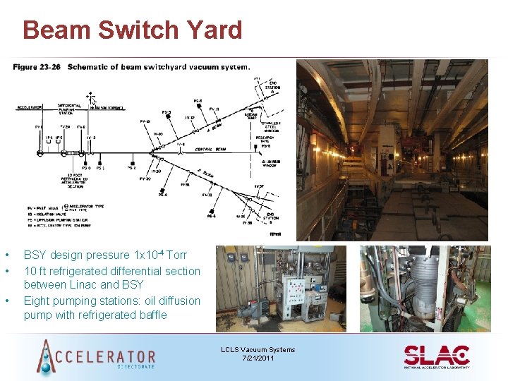
Beam Switch Yard • • • BSY design pressure 1 x 10 -4 Torr 10 ft refrigerated differential section between Linac and BSY Eight pumping stations: oil diffusion pump with refrigerated baffle LCLS Vacuum Systems 7/21/2011
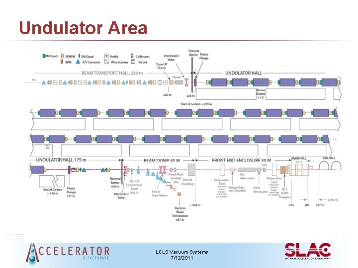
Undulator Area LCLS Vacuum Systems 7/12/2011
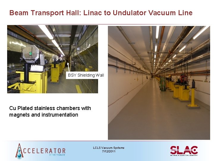
Beam Transport Hall: Linac to Undulator Vacuum Line BSY Shielding Wall Cu Plated stainless chambers with magnets and instrumentation LCLS Vacuum Systems 7/12/2011
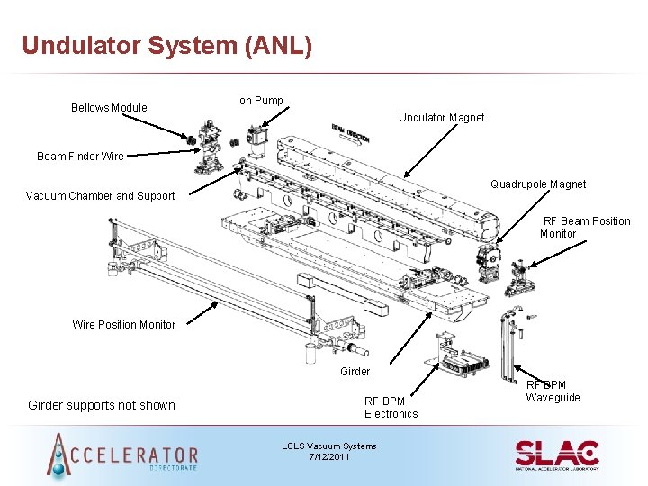
Undulator System (ANL) Bellows Module Ion Pump Undulator Magnet Beam Finder Wire Quadrupole Magnet Vacuum Chamber and Support RF Beam Position Monitor Wire Position Monitor Girder supports not shown RF BPM Electronics LCLS Vacuum Systems 7/12/2011 RF BPM Waveguide
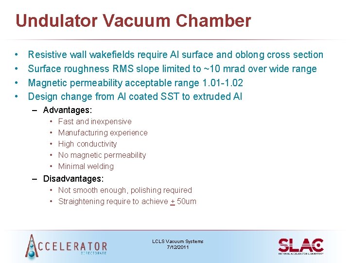
Undulator Vacuum Chamber • • Resistive wall wakefields require Al surface and oblong cross section Surface roughness RMS slope limited to ~10 mrad over wide range Magnetic permeability acceptable range 1. 01 -1. 02 Design change from Al coated SST to extruded Al – Advantages: • • • Fast and inexpensive Manufacturing experience High conductivity No magnetic permeability Minimal welding – Disadvantages: • Not smooth enough, polishing required • Straightening require to achieve + 50 um LCLS Vacuum Systems 7/12/2011
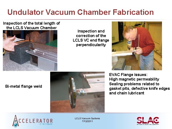
Undulator Vacuum Chamber Fabrication Inspection of the total length of the LCLS Vacuum Chamber Inspection and correction of the LCLS VC end flange perpendicularity EVAC Flange issues: High magnetic permeability Sealing problems related to gasket pits, defective knife edges and chain lubricant Bi-metal flange weld LCLS Vacuum Systems 7/12/2011
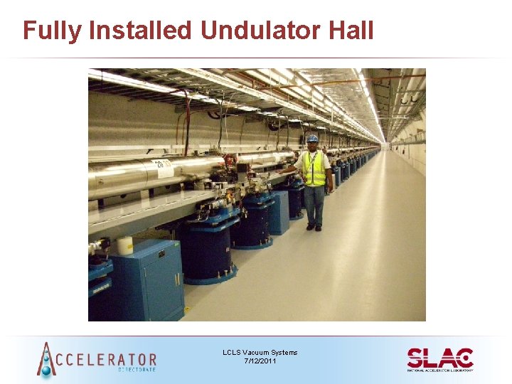
Fully Installed Undulator Hall LCLS Vacuum Systems 7/12/2011
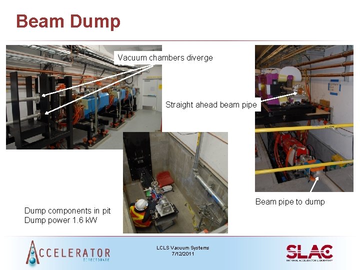
Beam Dump Vacuum chambers diverge Straight ahead beam pipe Beam pipe to dump Dump components in pit Dump power 1. 6 k. W LCLS Vacuum Systems 7/12/2011
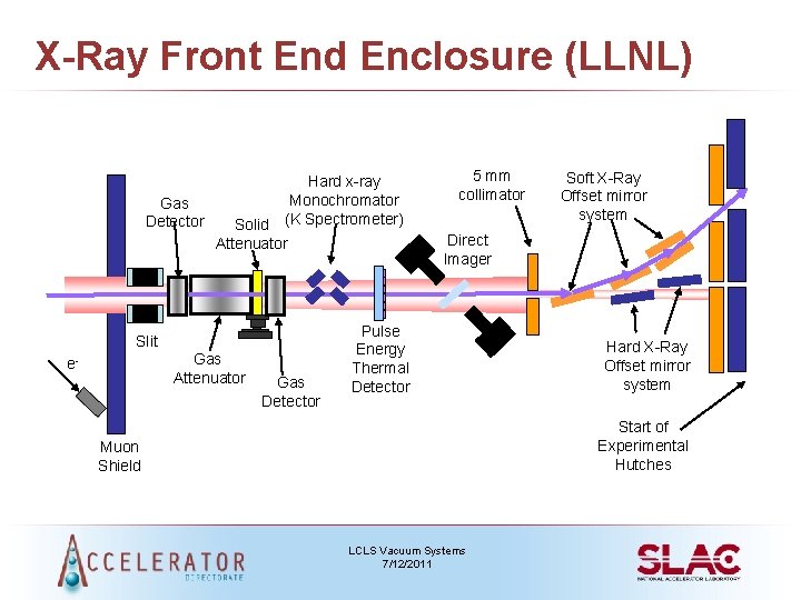
X-Ray Front End Enclosure (LLNL) Gas Detector Hard x-ray Monochromator (K Spectrometer) Solid Attenuator Slit Gas Attenuator e- Gas Detector 5 mm collimator Soft X-Ray Offset mirror system Direct Imager Pulse Energy Thermal Detector Hard X-Ray Offset mirror system Start of Experimental Hutches Muon Shield LCLS Vacuum Systems 7/12/2011
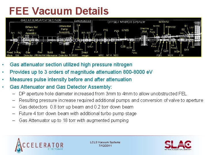
FEE Vacuum Details • • Gas attenuator section utilized high pressure nitrogen Provides up to 3 orders of magnitude attenuation 800 -8000 e. V Measures pulse intensity before and after attenuation Gas Attenuator and Gas Detector Assembly: – – – DP aperture hole diameter increased from 3 mm to 4 mm to allow unobstructed FEL Resulting pressure increase required additional pumps and conversion of valve to aperture Gas detectors 0. 8 torr up beam and 0. 2 torr down beam Future 4 torr down beam with additional turbo pump stage Gas Attenuator up to 18 torr with augmented pumping LCLS Vacuum Systems 7/12/2011
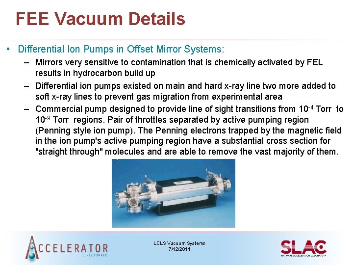
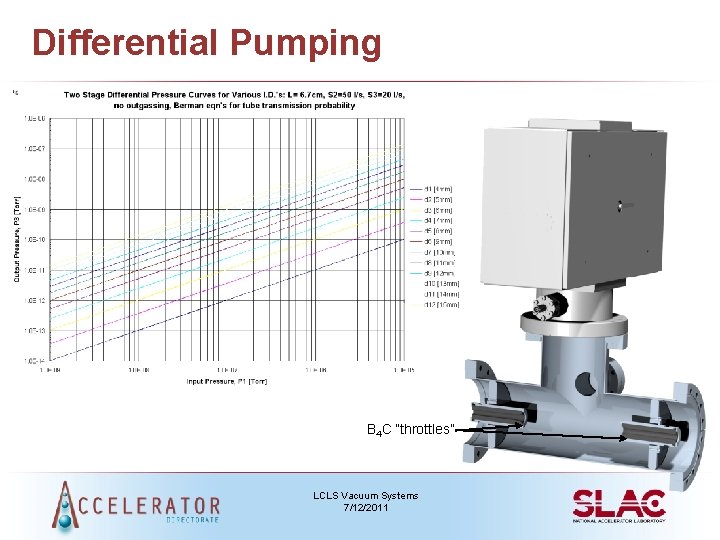
FEE Vacuum Details • Differential Ion Pumps in Offset Mirror Systems: – Mirrors very sensitive to contamination that is chemically activated by FEL results in hydrocarbon build up – Differential ion pumps existed on main and hard x-ray line two more added to soft x-ray lines to prevent gas migration from experimental area – Commercial pump designed to provide line of sight transitions from 10 -4 Torr to 10 -9 Torr regions. Pair of throttles separated by active pumping region (Penning style ion pump). The Penning electrons trapped by the magnetic field in the ion pump's active pumping region have a substantial cross section for "straight through" molecules and are able to remove the vast majority of them. LCLS Vacuum Systems 7/12/2011
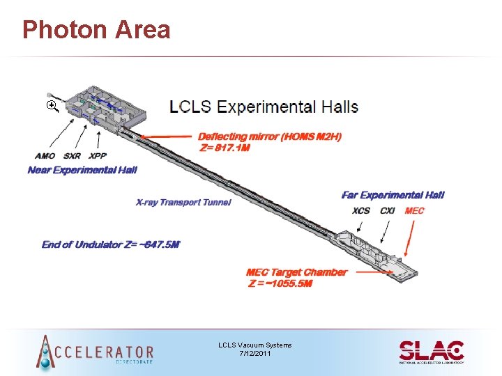
Photon Area LCLS Vacuum Systems 7/12/2011
Coherent X-Ray Imaging Instrument • Uses hard X-ray pulses from LCLS to image single sub-micron particles • The full transverse coherence of the LCLS laser allows single particles to be imaged at high resolution while the short pulse duration will limit radiation damage during the measurement • Allows imaging of biological samples beyond the damage limit that cannot be overcome with synchrotron sources • Samples introduced to the x-ray beam either fixed on targets or using a particle injector that delivers free-standing particles to the beam • High quality focusing optics will generate three foci (10 nanoparticles) of various sizes, with the hope of pushing the limit down to single biomolecules LCLS Vacuum Systems 7/12/2011
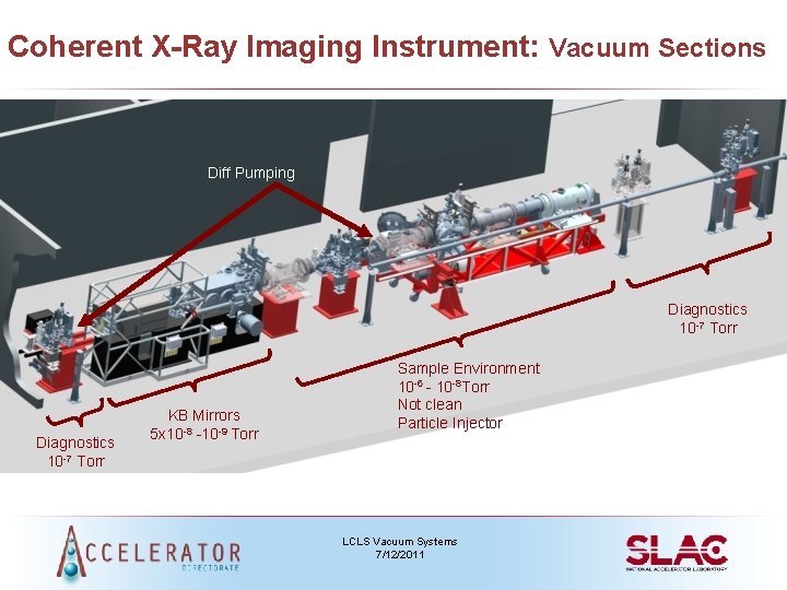
Coherent X-Ray Imaging Instrument: Vacuum Sections Diff Pumping Diagnostics 10 -7 Torr KB Mirrors 5 x 10 -8 -10 -9 Torr Sample Environment 10 -6 - 10 -8 Torr Not clean Particle Injector LCLS Vacuum Systems 7/12/2011
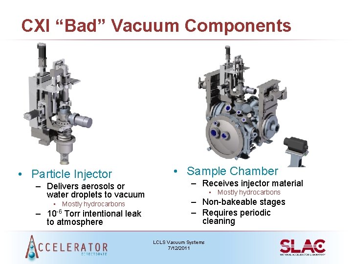
CXI “Bad” Vacuum Components • Particle Injector – Delivers aerosols or water droplets to vacuum • Mostly hydrocarbons – 10 -6 Torr intentional leak to atmosphere • Sample Chamber – Receives injector material • Mostly hydrocarbons – Non-bakeable stages – Requires periodic cleaning LCLS Vacuum Systems 7/12/2011
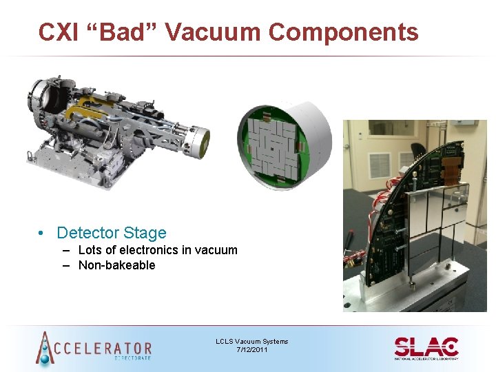
CXI “Bad” Vacuum Components • Detector Stage – Lots of electronics in vacuum – Non-bakeable LCLS Vacuum Systems 7/12/2011
Differential Pumping B 4 C “throttles” LCLS Vacuum Systems 7/12/2011
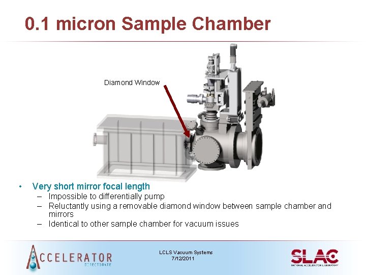
0. 1 micron Sample Chamber Diamond Window • Very short mirror focal length – Impossible to differentially pump – Reluctantly using a removable diamond window between sample chamber and mirrors – Identical to other sample chamber for vacuum issues LCLS Vacuum Systems 7/12/2011
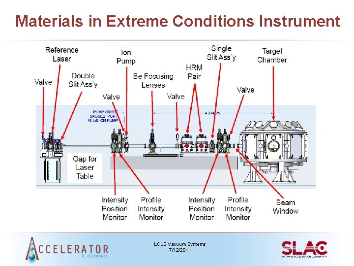
Materials in Extreme Conditions Instrument • Combines the unique LCLS beam with high power optical laser beams and a suite of dedicated diagnostics tailored for this field of science including: Ø X-ray Thomson scattering spectrometer Ø XUV spectrometer Ø Fourier domain interferometer Ø VISAR system • Large vacuum target chamber makes the end-station very versatile, it has been designed to service key scientific areas including Warm Dense Matter physics, high pressure studies, shock physics, and high energy density physics LCLS Vacuum Systems 7/12/2011
Materials in Extreme Conditions Instrument LCLS Vacuum Systems 7/12/2011
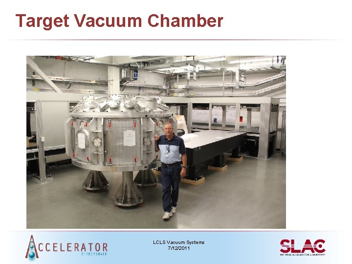
Target Vacuum Chamber • Modeled after LLNL Titan & LANL Trident Target Chambers • Operating pressure 10 -6 Torr • Pressure will increase inside chamber due to warm dense matter or high density matter – Requires Be window and differential pumping to protect X-ray optics • Multiple sample changes • Must achieve 10 -6 Torr within 20 to 30 minutes pump down time – Two roughing pumps, one turbo pump and two cryo-pumps LCLS Vacuum Systems 7/12/2011
Target Vacuum Chamber LCLS Vacuum Systems 7/12/2011
Summary • LCLS vacuum systems – Unites the old with the new – Need to keep pressure regimes segregated • LCLS is performing extremely well – Wouldn’t be possible without successful vacuum systems – Still room for improvements, but challenges make life interesting • Next on the horizon…. . LCLS II LCLS Vacuum Systems 7/12/2011