Investigating the utility of Schwarz Christoffel mapping theory











- Slides: 38
Investigating the utility of Schwarz. Christoffel mapping theory for electric machine design and analysis Tim C. O’Connell Doctoral Student; Advisor: P. T. Krein University of Illinois at Urbana-Champaign Grainger CEME teleseminar Monday, April 24 th, 2006
Overview • Machine design overview • Schwarz-Christoffel (SC) mapping • Application to motor design • Examples • Comparison to Finite Element Analysis (FEA) • Conclusions 2
Overview • Machine design overview • Schwarz-Christoffel (SC) mapping • Application to motor design • Examples • Comparison to Finite Element Analysis (FEA) • Conclusions 3
Machine design overview 1) Shape • Used to steer the flux 2) Materials • Affect efficiency, weight, acoustic properties, manufacturability, cost 3) Sources • Characteristics and placements of currents • Types and placement of permanent magnets 4
Machine design overview Standard Methods • Equivalent circuit models • use lumped parameters • derived empirically • may ignore certain higher order effects • Magnetic circuit models • usually assume the flux direction • fringing is empirically modelled • force derived from coenergy formulations 5
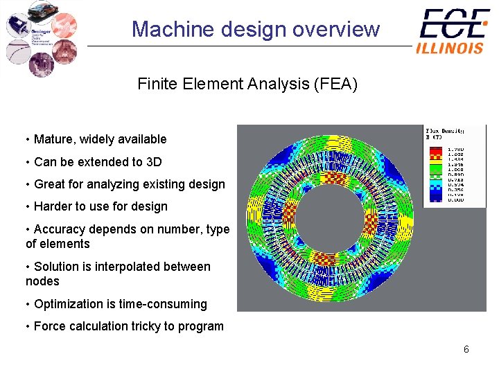
Machine design overview Finite Element Analysis (FEA) • Mature, widely available • Can be extended to 3 D • Great for analyzing existing design • Harder to use for design • Accuracy depends on number, type of elements • Solution is interpolated between nodes • Optimization is time-consuming • Force calculation tricky to program 6
Overview • Machine design overview • Schwarz-Christoffel (SC) mapping • Application to motor design • Examples • Comparison to FEA • Conclusions 7
SC mapping Def’n: A Schwarz-Christoffel map is a function f of the complex variable z that conformally maps a canonical domain in the zplane (a half-plane, unit disk, rectangle, infinite strip) to a “closed” polygon in the w-plane. iv iy z-plane x w-plane w = f(z) u 8
SC mapping Def’n: A conformal transformation is a complex transformation that preserves angles locally. In other words, if Γ 1 and Γ 2 are two curves that intersect at an angle θz in the z-plane at point p, then the images f(Γ 1) and f(Γ 2 ) intersect at an angle θw = θz at q = f(p). • All analytic, one-to-one mappings are conformal θz f(Γ 1) Γ 1 p Γ 2 w = f(z) θw = θz q f(Γ 2) 9
SC mapping Def’n: Let f(z) = f(x+iy) = g(x, y) + i h(x, y) be an analytic function of z. Then f satisfies Laplace’s equation and g and h satisfy the Cauchy-Reimann equations and are conjugate functions. Thus, if one of g or h describes a scalar potential function, then the other will describe the corresponding field lines. h(x, y) = c 1 h(x, y) = c 2 g(x, y) = 1. 75. 50. 25 g(x, y) = 0 10
SC mapping Thm: Fundamental Theorem of Schwarz-Christoffel Mapping Let D be the interior of a polygon P having vertices w 1, … , wn and interior angles α 1 π, … , αn π in counterclockwise order. Let f be any conformal map from the unit disk E to D. Then for some complex constants f(z 0) and C, where f(zk) = wk for k = 1, … , n. z-plane iy z 2 E w-plane z 1 z 0 zn x w = f(z) iv w 2 α 2=1/2 f(z 0) wn P u w 1 11
SC mapping SC parameter problem: how do we determine the correct location of the prevertices zk? z-plane iy z 2 , , C ) z 0 z 1 f( z 1 z 0 zn , … , zn x f(z 0 ), Actual polygon with incorrect prevertices C, z 1 , … , z n Desired polygon 12
SC mapping • Most problems have no analytic solution for the prevertices • For n>3 vertices, unless lots of symmetry, no analytic solution • Numerical solution required for 1. Solving the parameter problem 2. Calculating the SC integral 3. Inverting the map 13
SC mapping Historical milestones – machine design with SC mapping • 1820’s: Gauss – idea of conformal mapping • 1867 -90: Schwarz and Christoffel discover SC formula and variants • 1900 -01: F. W. Carter uses SC mapping for field between poles • “I by no means recommend that one should go to the trouble of using these somewhat difficult formulae in average practical cases…” – Carter • 1980: Trefethen – SCPACK FORTRAN program • 1996: Driscoll – SC Toolbox for Matlab® • 1998: Driscoll and Vavavis – CRDT algorithm for multiply elongated regions 14
Overview • Machine design overview • Schwarz-Christoffel (SC) mapping • Application to motor design • Examples • Comparison to FEA • Conclusions 15
Application to motor design Design goal: Calculate the electromagnetic fields and corresponding rotor torques/forces for a given geometry and set of materials and sources 16
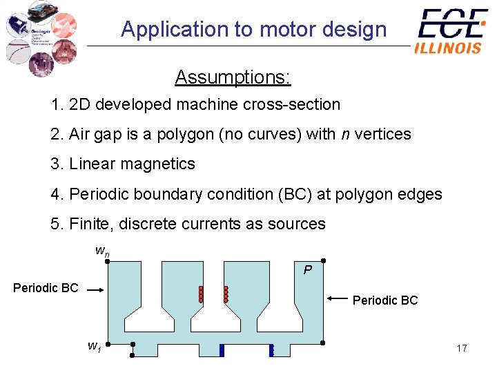
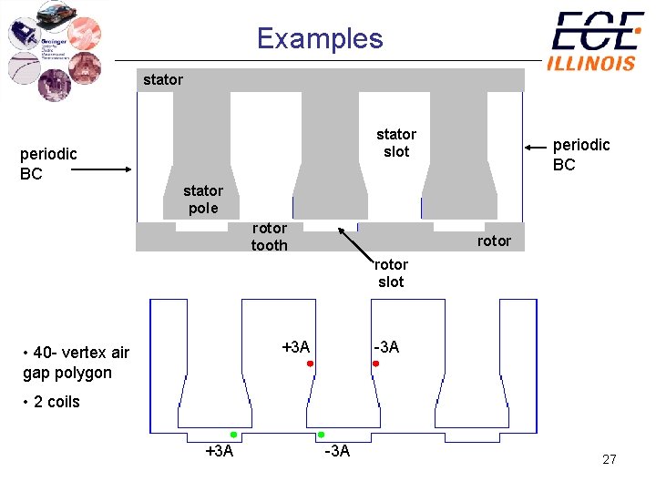
Application to motor design Assumptions: 1. 2 D developed machine cross-section 2. Air gap is a polygon (no curves) with n vertices 3. Linear magnetics 4. Periodic boundary condition (BC) at polygon edges 5. Finite, discrete currents as sources wn P Periodic BC w 1 17
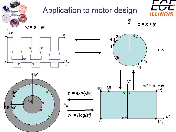
Application to motor design iy w = u + iv 40 z = x + iy 35 1 x 15 14 iy’ iv’ 35 z’ = exp(-iw’) 1, 14 15, 40 40 35 w’ = u’ + iv’ 15 x’ w’ = i log(z’) 1 1418 u’
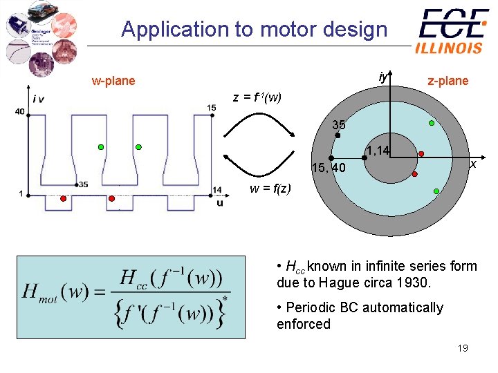
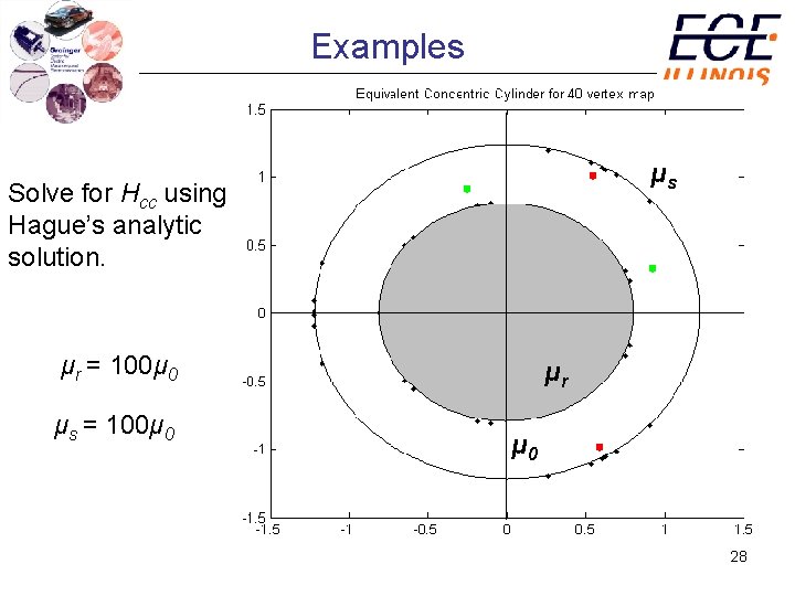
Application to motor design iy w-plane z = f-1(w) 35 1, 14 x 15, 40 w = f(z) • Hcc known in infinite series form due to Hague circa 1930. • Periodic BC automatically enforced 19
Application to motor design SC Toolbox for MATLAB® • Released in 1996 • Solves parameter problem for half-plane, disk, strip, rectangle, and exterior maps • Cross-ratio formulation of the parameter problem for multiply elongated regions (CRDT) • Computes forward and inverse maps • Computes derivative of maps (easier) • Graphical and object-oriented user interfaces 20
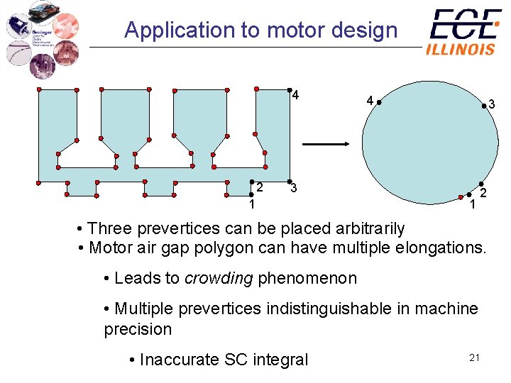
Application to motor design 4 2 4 3 3 1 1 2 • Three prevertices can be placed arbitrarily • Motor air gap polygon can have multiple elongations. • Leads to crowding phenomenon • Multiple prevertices indistinguishable in machine precision • Inaccurate SC integral 21
Application to motor design CRDT algorithm • Eliminates crowding problem • Driscoll and Vavasis 1998 • Incorporated in the SC Toolbox • Very well suited for multiply-elongated regions • Tends to be O(n 3) 22
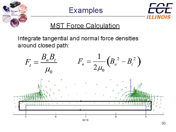
Application to motor design Force/torque calculation 1. Coulomb Virtual Work (CVW) method • Standard for FEA analyses • Coenergy method • Eases path dependencies inherent in FEA mesh 2. Maxwell Stress Tensor (MST) method • Integrate the MST around a closed path • Highly path- and element-dependent for FEA • Ideal for SC solution • No path dependence 23
Overview • Machine design overview • Schwarz-Christoffel (SC) mapping • Application to motor design • Examples • Comparison to FEA • Conclusions 24
Examples 12 1 1 12 10 11 Infinite vertices are mapped to the circle; crowding occurs. 25
Examples • Infinite strip map used to plot field lines • Constant potential surfaces • Periodic BC not enforced here 26
Examples stator periodic BC stator slot periodic BC stator pole rotor tooth rotor slot +3 A • 40 - vertex air gap polygon -3 A • 2 coils +3 A -3 A 27
Examples μs Solve for Hcc using Hague’s analytic solution. μr = 100μ 0 μs = 100μ 0 μr μ 0 28
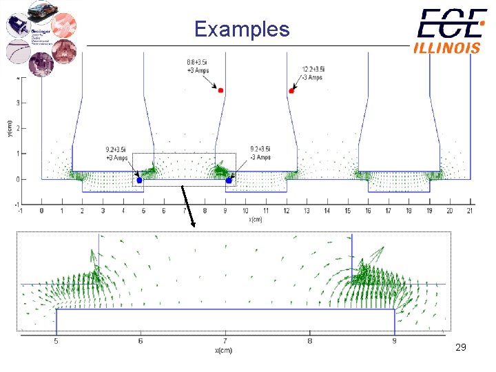
Examples 29
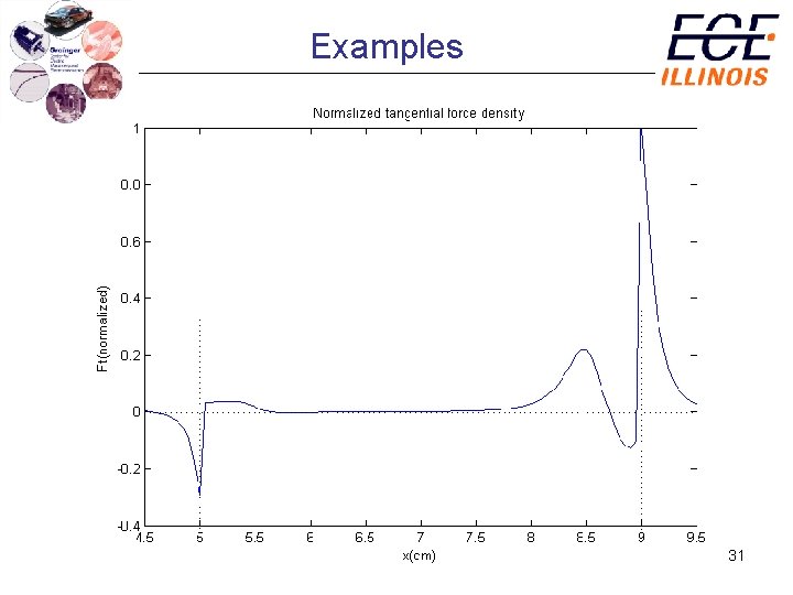
Examples MST Force Calculation Integrate tangential and normal force densities around closed path: 30
Examples 31
Examples 32
Overview • Machine design overview • Schwarz-Christoffel (SC) mapping • Application to motor design • Examples • Comparison to FEA • Conclusions 33
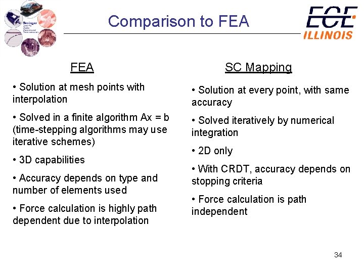
Comparison to FEA SC Mapping • Solution at mesh points with interpolation • Solution at every point, with same accuracy • Solved in a finite algorithm Ax = b (time-stepping algorithms may use iterative schemes) • Solved iteratively by numerical integration • 3 D capabilities • Accuracy depends on type and number of elements used • Force calculation is highly path dependent due to interpolation • 2 D only • With CRDT, accuracy depends on stopping criteria • Force calculation is path independent 34
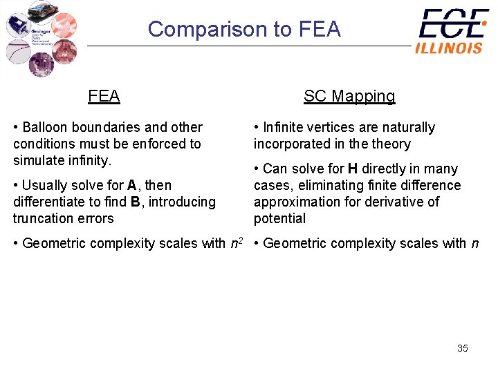
Comparison to FEA • Balloon boundaries and other conditions must be enforced to simulate infinity. • Usually solve for A, then differentiate to find B, introducing truncation errors SC Mapping • Infinite vertices are naturally incorporated in theory • Can solve for H directly in many cases, eliminating finite difference approximation for derivative of potential • Geometric complexity scales with n 2 • Geometric complexity scales with n 35
Overview • Machine design overview • Schwarz-Christoffel (SC) mapping • Application to motor design • Examples • Comparison to FEA • Conclusions 36
Conclusions • Design benefits • accurate field and force calculation • may be possible to design in conc. cylinder domain • Iterative map solution still hides some of the variable dependencies from the designer • Solution scaling • problem complexity grows with n, but CRDT is O(n 3). May be OK since parameter problem solved only once • FEA problem complexity grows with n 2 37
Conclusions • Can be useful when fields near sharp corners of poles and teeth are needed to high accuracy • SC mapping is a promising technique due to its accuracy 38