Image reconstruction and analysis for Xray computed microtomography


/(Iflat –Idark )")


- Slides: 27
Image reconstruction and analysis for X-ray computed microtomography Lucia Mancini 1, Francesco Montanari 2, Diego Dreossi 3 1 Elettra - Trieste 2 A. R. P. A. of Palmanova (UD) 3 University of Trieste
The SYRMEP beamline SR laminar beam ELETTRA bending magnet vacuum slit system ionization chamber air slit system double Si(111) monochromator sample Source size s (h x v) 1100 mm x 100 mm Source-to-sample distance: D 24 m Beam size at sample (h x v) 150 mm x 6 mm Energy range: 8 ÷ 35 ke. V, Bandwidth l/l 2 x 10 -3 Typical fluxes at 15 ke. V 2 * 108 phot. /mm 2 s (@ 2 Ge. V, 300 m. A) 7 * 108 phot. /mm 2 s (@ 2. 4 Ge. V, 180 m. A) digital detector or radiographic film
The experimental set-up at SYRMEP CCD camera Sample Scintillator Screen PC y d q z Monochromatic incident X-ray beam x Sample Stage Planar Radiographs CCD camera: 2048 x 2048 pixels 2, pixel size: 14 µm, FOV: 28 x 28 mm 2. A magnifying optics is also available giving a pixel size of 3. 85 µm and a FOV of 7. 9 x 7. 9 mm 2.
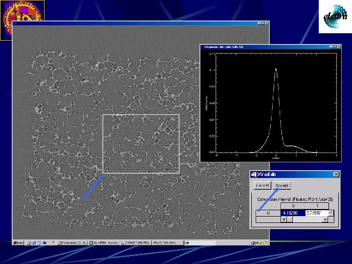
Elaboration of tomographic images Planar radiographs are elaborated by a reconstruction procedure: filtered backprojection algorithm [Herman, 1980] for each projection an intensity map is recorded in the xy detector plane projections are submitted to filtering procedures each intensity map is back projected along the normal to the projection itself finally, the intensities are added for all the projections Reconstructed slices are then treated by a rendering procedure: 2 D slices visualized as Stack 3 D views of the sample can be obtained (Volume rendering) Rendered images can be elaborated applying filters, false colors, segmentation tools to extract quantitative information. Principles of Computerized Tomographic Imaging Avinash C. Kak www. slaney. org/pct-toc. html
Choice of the number of projections The number of projections Mproj should be roughly equal to the number of rays Nray (the sampling points) in each projection: Mproj/ Nray p/2 Mark Rivers, University of Chicago Tutorial Introduction to X-ray Computed Microtomography www-fp. mcs. anl. gov/xray-cmt/rivers/
Recording of tomographic images Sample image Flat field image Dark field image
Flat procedure for the tomographic images Iflatted = (Isample –Idark )/(Iflat –Idark )
Run Compile The reconstruction procedure by IDL
Starting of the reconstruction procedure
Choice of the slice to reconstruct Select the number of the slice to reconstruct and press Enter to select it Slice number 200
Creation of the sinogram
Choice of the reconstruction parameters
Slice reconstruction: optimization of the rotation center C = 624. 750 C = 630. 750 C = 638. 750 A poor centering causes arc artifacts. An automated centering procedure gives a sinogram which is better centered on the rotation axis by determining the centerof-gravity of each row in the sinogram, and fitting this center-of-gravity array to a sin wave. The symmetry axis of the fitted sin wave is the rotation axis. The sinogram is then shifted left or right so that the rotation axis is exactly on the center column of the sinogram array.
Slice reconstruction: good rotation center No more artifacts visible on this image
Ring artifacts reduction The ring artifacts are due to drifts or non -linearities in the detector response. A bad detector element will show up as a vertical stripe in the sinogram. Two vertical lines in the sinogram would appear as a a thin cylinder centered on the rotation axis in the real object. The causes of these vertical stripes in the sinogram can include the following: Drifts in the detector element sensitivity in between white-field calibrations Non-linear detector element response Higher energy harmonics in the incident beam
How to reduce the ring artifacts? Compute the average row of the sinogram by summing down each column and dividing by the number of rows. This average row should have very little highfrequency content, since real objects will be moving in the sinogram, and will be blurred out when computing the average row. Compute the magnitude of these detector anomalies by subtracting a smoothed version of the average row from the average row. Subtract the result of previous step, the detector anomalies, from each row in the sinogram. This results in a sinogram with much less vertical striping.
Result of the ring artifacts reduction Before After
Zinger removal A close look to the reconstructed slice can also reveal perfectly straight, bright lines at random orientations in the image. These bright lines, which look like scratches, are due to zingers, or anomalously bright pixels, in the raw images. These zingers are caused by cosmic rays or scattered X-rays hitting the CCD chip directly, causing large energy deposition relative to the visible light photons from the scintillator crystal. Eliminating these zingers is best done when the raw data and white field images are first read in.
How to remove zingers? Smooth the raw image with a low-pass filter Subtract the raw image from the smoothed image Divide the difference image from step 2 by the smoothed image to produce an image of anomalous pixels on a relative scale Any pixels in the image from step 3 which are greater than a threshold value (typically 1. 2) are defined to be zingers. The intensity of zinger pixel at location N is replaced by the average intensity of the pixels at location N-2 and N+2. Pixels N-1 and N+1 are not used because some zingers affect 2 adjacent pixels.
Volume reconstruction You cannot create more than 100 sinograms at once
After having created all the sinograms you need, you can reconstruct all the corresponding slices at once.
8 bit. raw volume creation
Data visualization: volume rendering
Volume rendering procedure
Slice visualizer
Volume rendering