HIPO Highspeed Imaging Photometer for Occultations Ted Dunham


- Slides: 32

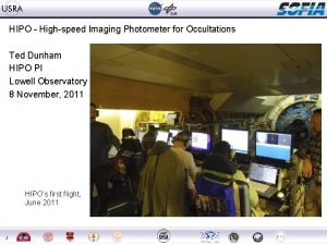
HIPO - High-speed Imaging Photometer for Occultations Ted Dunham HIPO PI Lowell Observatory 8 November, 2011 HIPO’s first flight, June 2011 1

Outline • Outline and purpose of the talk • HIPO science capabilities and related topics • Instrument design – Mechanical, optical, electronic – Operating modes • Examples of possible observation-specific instrument modifications • HIPO status and in-flight performance – Pluto occultation! • Observatory performance • HIPO and observatory characterization work in progress • Questions? 2

HIPO Science Capabilities • Stellar Occultation Observations – Atmospheric sounding & accurate sizes of solar system objects • • Pressure, density, temperature at microbar atmospheric levels Vertical and horizontal atmospheric structures can be resolved Repeated occultations can track atmospheric changes Spatial resolution of a few km at 30 AU for KBO sizes • Extrasolar planet transits – Multi-wavelength transit observations at high SNR (we hope!) • FLIPO configuration of particular interest - 0. 3 to 5 microns • Planetary temperatures, radii, atmospheric composition, … • Asteroseismology – Obtain necessary SNR for measuring oscillations in bright stars • Short observing periods available (by Kepler standards) • Observatory test work – Some modifications made particularly for this purpose 3

Occultation Observational Requirements • Must be in the occultation track, object above the horizon, sun below it, and with good weather • Time and position resolution and accuracy – 20 -50 ms resolution to resolve Fresnel zone in some cases – ~1 ms time and ~30 meter position accuracy for high S/N ring events • Reliable, redundant instrument to ensure data are obtained • Two or three wavelength observations often desirable • Imaging photometry desirable – Simultaneous observation of field standards if available – Subtract complex backgrounds (e. g. Neptune near Triton, Saturn’s rings) • Largest possible telescope and maximum throughput – Optimize S/N for a fixed event velocity – Maximize number of events observable with high S/N • Flexible optical, filter, and readout configurations to optimize for particular events • Observations straightforward, but absolutely unforgiving of error 4

Related SOFIA Characteristics • 2. 5 meter telescope – Largest “portable” telescope ever • Boeing 747 SP aircraft – Long range aircraft, ~0. 7 DEarth coverage from operation base – Allows for late prediction updates – Flexible Deployment Options • No natural restrictions – Safe aircraft operation limits – Political & security restrictions • Commercial airfield operations • • 5 Clouds very rare Low scintillation noise level Stable stratospheric transmission Smooth PSF

Scintillation Noise Very low scintillation noise level expected Sunday night I think I saw signs of this for the first time! Stratosphere Scintillation? Jet Stream or tropopause ~10 km Long propagation path causes scintillation Image Motion Dunham & Elliot, PASP 95, 325 -331 (1983) 6

Related Considerations • HIPO is a CCD instrument, not in SOFIA’s IR ‘sweet spot’ – Rationale for airborne work: • Mobility, ephemeral events • Precise photometry – Low scintillation – Stable long-term photometry (a work in progress) • “Custom” observations – Flexibility of configuration essential – Modifications may be needed to optimize the observation • Therefore HIPO is a Special Purpose Science Instrument – Avoids the rigidity of a facility instrument – Collaboration with team needed to make best use of instrument 7

HIPO Configuration - Optical and Mechanical • Configuration Options – 1. One or two optical channels • Internal dichroic beamsplitter – 2. FLITECAM co-mount (aka FLIPO) • Gold dichroic beamsplitter • Throughput reduction 4 – 3. Gate valve window 1 • Eliminates possible seeing issue – 4. Bare CCD (no reimaging optics) • • 8 Major reconfiguration, not shown ~30% better throughput ~1’ field at 0. 055”/pixel Binning speed penalty 2 3

HIPO (June) and FLIPO (August & October) 9

HIPO Configuration - Electronics • Redundant design • • • Two Channels GPS time/pos’n Hardware timing Flexible readouts Mounted spares for single string items – Network Switch – Mac Mini – Netra T 1 s • • • 10 Full spares set Fallback options Phase-locked chopper control possible Mac Mini Supervisor

HIPO Observing Modes Mode Name Comments Find Repeated readout, used for field acquisition Single Frames Ordinary CCD imaging; most cameras only do this Basic Occultation Time series with full readout flexibility, multiple subframes. Fast Occultation Better duty cycle than basic occultation at high frame rates but only a single subframe can be supported Pipelined Occultation Faster integration interval than fast occultation, but only certain special subframes can be supported Fast Dots Very fast, uses CCD as analog storage so limited duration. Used for telescope test work. Slow Dots Not very useful with frame transfer CCDs. Strip Scanning Used for ground-based prediction astrometry & telescope test. Often called TDI mode. Reference: Dunham, et al. , Proc SPIE 7014, 164 -173 (2008) 11

Examples of possible modifications • Custom filters – UBVRI and a 0. 89 µm methane filter is current set – Possible grism implementation • Custom beamsplitters – 0. 675 and 0. 575 µm transition optical dichroics – FLITECAM beamsplitter coating should be improved • Software modifications as necessary – Ongoing now, expect this to continue for some time • Different CCD control electronics – Transitioning to Gen III Leach controllers & linux computers • Age consideration, not so much performance – Entirely different controllers could be considered • Better detectors – Deep depletion CCDs, much better AR coatings now available – CMOS detectors will evenutally replace CCDs 12

HIPO Status • Heavily used in test work – Ground operations in 2004, 2008, 2011 – First two flights in late June 2011 (SCAI-1 and -2) • Mostly test work, but first science result too! – Pluto occultation observed as part of SCAI-2 – Four additional flights in October 2011 (SCAI-3 through -6) – Final test work prior to Segment 3 downtime in December 2011 • Commissioning – Necessary observations made during test flights this year • Final results pending reasonable analysis of the data – Integration with the MCCS accomplished for October flights • Main control requirements are positioning and focusing • Ready to go for Segment 3 (Cycle 1) science flights 13

HIPO Lab Performance Parameter Discussion Read Noise 3 e- at 200 kpx/sec and 8 e- at 1 Mpx/s, both unbinned. 11 e- at 1 Mpx/s binned 3 x 3. Sky limited in most cases. Time Accuracy 3. 5 microsecond delay in DSP trigger loop Position accuracy 5 meters (SA off), GPS limited, but more on this later Read rate 11 -22 Hz, 3 80 x 80 subframes binned 3 x 3 depending on pos’n 80 Hz, 1 80 x 80 subframe binned 3 x 3 in pipelined occ. mode Optics Throughput Blue side: 66 -73% for 0. 34 - 0. 64 micron range Red side: 72 -82% for 0. 46 - 1. 0 micron range CCDs e 2 v CCD 47 -20 1 K frame transfer, thinned back-illuminated e 2 v CCD 67 256 x 256 frame transfer, thinned back-illuminated Field of View 5. 7’ square, 0. 33 “/pixel (unbinned) w/ reimaging, CCD 47 2. 8’ square, 0. 66 “/pixel (unbinned) w/ reimaging, CCD 67 Reference: Dunham, et al. , Proc SPIE 7014, 164 -173 (2008) 14

HIPO Flight Performance, I • Throughput – Determined in flight using Feige 110 (a spectrophotometric standard star) – In line with expectations based on optical element coatings, CCD QE, telescope coatings, atmospheric transmission – The FLITECAM dichroic should be improved • HIPO transmission is ~50% • Emissivity at 3. 1 µm is ~13% – The dichroic tertiary is a Serious Problem for HIPO • Design requirements are to reflect well in the IR, transmit well at CCD wavelengths. It is quite successful at this. • A project is now underway to implement the long-planned fully reflective tertiary 15

HIPO Flight Performance, II 16

HIPO Flight Performance, III • GPS – GPS clocks provide once/second fixes – Tested by comparing to the facility Ashtech unit • Pegged in the vicinity of Edwards using differential GPS – Discrepancies noted during the test: • The facility unit had trouble tracking satellites on SCAI-1 for ~1 hour – Don’t know why. No problem on SCAI-2; SCAI-3 through -6 TBD. • All units show short glitches when adding/deleting satellites – Easily detected and interpolated • The facility unit shows altitudes typically 30 meters higher than the HIPO units. – This is probably a coordinate system difference; needs investigation 17

HIPO Flight Performance, IV • Positioning accuracy – Stars positioned to ~0. 5” rms – Worst outlier in test was 2” – Outliers can be eliminated by an additional move iteration • Test consisted of A-B offsets on two different stars – A spots plotted as is – B spots offset in X by 2. 0” 18

• Occultation opportunity arose – Fit in with SCAI activity – Targeted the occultation centerline • • • Simultaneous FDC data solved the tertiary mirror problem First flight into remote waters In-flight prediction update – Hours-old astrometric data used • 19 Actual flight plan somewhat shorter than this Pluto Occultation

Pluto Occultation, Cont’d • Central brightening seen in all lightcurves • Post-event fit to three chords indicates impact parameter < 25 km! • Should have seen much brighter and sharper central flash than this – Extinction? • If so, episodic – Atmospheric asymmetry? • Paper in development • In-air prediction data obtained; need to evaluate for possible future use. • Precisely targeted predictions a new capability. 20

Airborne Imaging, I • Free atmosphere seeing probably negligible • Shear layer seeing - FAST! – Strongly wavelength dependent. Major factor for HIPO. • Telescope cavity seeing – May be difficult to separate from shear layer. – Practically speaking may not be relevant for some time. • Optical figure error and alignment (includes focus) – Separable using Shack-Hartmann analysis • Well understood; not a major factor at present • Temperature-dependent astigmatism seen – Instrument optical errors may be important in some cases • Jitter – Separable using high-speed imaging – Biggest overall problem; active work area - more on this later • Tracking errors 21

Airborne Imaging, II Figure from original instrument proposal call 0. 3 m 1. 0 m 1. 5 m 2. 0 m Diffraction and shear layer scattering only Signs of this behavior may be appearing in FLIPO images Real images include everything, especially jitter 22

Airborne Imaging, III Long exposures like this 1 second one have a smooth profile with broad wings, very similar to KAO images. There is significant encircled energy at large aperture radii, as expected. 23

Airborne Imaging, IV SOFIA images at HIPO wavelengths are fuzzy puffballs all the way down to 200 µs exposures. KAO images broke up into speckles at short exposure times. Are there lots more, very small speckles in the SOFIA images? 500 us KAO images 24 200 us exposure 1 ms exposure 2 ms exposure [note jitter]

Airborne Photometry, V Expected behavior of SOFIA images from wind tunnel test results and telescope FEM. Real experience shows larger jitter. Later improvement in pointing stability Shear layer and diffraction only 25 Early FLIPO images FORCAST first light!

Focus vs. Temperature • The TA focus is very sensitive – Timescale for significant focus change can be ~minutes • Obtained many points with HIPO Shack. Hartmann capability • Allan Meyer’s explorations of temperature correlations shown here. 26

Jitter, I • Jitter is a major problem area – Expected to be a problem for years – Biggest contributor to image size – Impacts photometric precision • Active Mass Dampers (AMDs) thought to be the best solution – Project to install these is on the brink of completion 27 • Movie details: – 1. 19 ms/frame (840 Hz) pipelined occultation – CCD 67, 2 x 2 binned, 4/3”/pixel

Jitter, II • Power spectra – XEL (top), EL (bottom) – Nyquist frequency 420 Hz – Main problems below 100 Hz; AMDs targeting these • 300 Hz peak suspiciously close to SMA control loop oscillation frequency • Quiet above 300 Hz, but need to check out to ~600 Hz to be sure 28

Gyro Drift • Gyro drift is compensated by tracking • Default drift values are quite good and pretty stable • New default drift value for LOS gyro (difficult to measure!) established in August 29 Zero the drift value Track a bit Track more • Gyro drift can be a limiting factor for some observational schemes - watch for this!

Pointing Accuracy • Blind pointing accuracy folds into operational efficiency on each observing leg • Tested blind pointing accuracy over a range of elevations on one heading • Generally within 10 -20 arcsec – Some evidence of trends – Occasional outliers • Abandoned further work on this bigger problems to deal with 30

Ongoing Work Items • Analysis of data from the SCAI flights is only beginning • More flights are coming in December – Hopefully with active mass dampers (AMDs) to reduce jitter • Data analysis priorities: – Evaluate scintillation noise more thoroughly – Understand jitter impact on photometric noise – Evaluate the precise photometry test • This is only a first attempt – Evaluate image quality vs. exposure time and wavelength – Misc. other items • Observatory priorities: – Evaluate and hopefully implement the AMDs – Pursue efficient spectroscopy through LOS resets – Other things that might arise from this meeting 31

Questions? 32
 Dsl highspeed
 Highspeed test
 Frc control system
 Dunham koppel
 Ian dunham
 Clasificacion de dunham y folk
 Cheryl dunham
 St mark's church dunham massey
 Para empezar
 Diagram hipo
 Pocas copas trabalenguas
 Hipo incident
 Hipo verbo
 Vtoc diagram
 Abostezo
 Juego de la goma cruzada
 Osmolaritate plasmatica
 Causas del hipo
 Hfo ácido
 Hipo diagram
 Laskin nozzle aerosol generator
 Photometer
 Atomabsorptionsspektroskopie auswertung
 Principle involved in flame photometry
 Typiska drag för en novell
 Verksamhetsanalys exempel
 Tack för att ni har lyssnat
 Shivaismen
 Centrum för kunskap och säkerhet
 Läkarutlåtande för livränta
 Inköpsprocessen steg för steg
 Påbyggnader för flakfordon
 Egg för emanuel
