Giordana Severino Presentation 7052015 ESR 2 2 WP


- Slides: 28
Giordana Severino Presentation 7/05/2015 ESR 2. 2, WP 2 CERN Supervisors Marco Buzio Academic supervisor Prof. Pasquale Arpaia
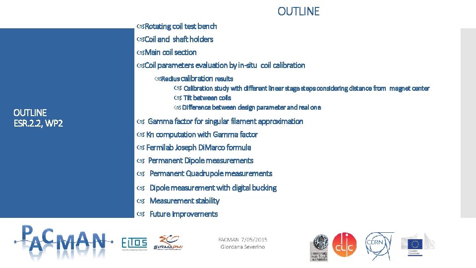
OUTLINE Rotating coil test bench Coil and shaft holders Main coil section Coil parameters evaluation by in-situ coil calibration OUTLINE ESR. 2. 2, WP 2 Radius calibration results Calibration study with different linear stage steps considering distance from magnet center Tilt between coils Difference between design parameter and real one Gamma factor for singular filament approximation Kn computation with Gamma factor Fermilab Joseph Di. Marco formula Permanent Dipole measurements Permanent Quadrupole measurements Dipole measurement with digital bucking Measurement stability Future Improvements
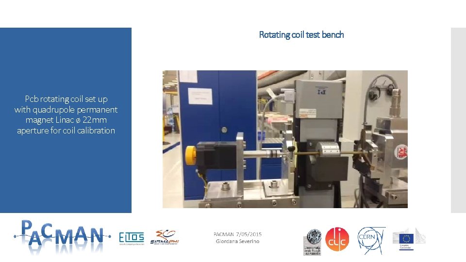
Rotating coil test bench Pcb rotating coil set up with quadrupole permanent magnet Linac ø 22 mm aperture for coil calibration
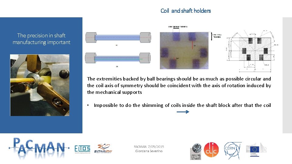
Coil and shaft holders The precision in shaft manufacturing important The extremities backed by ball bearings should be as much as possible circular and the coil axis of symmetry should be coincident with the axis of rotation induced by the mechanical supports • Impossible to do the shimming of coils inside the shaft block after that the coil
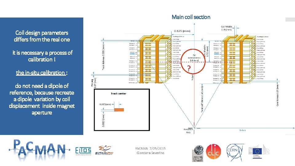
Main coil section Coil design parameters differs from the real one it is necessary a process of calibration ! the in-situ calibration : do not need a dipole of reference, because recreate a dipole variation by coil displacement inside magnet aperture ?
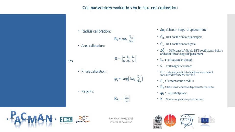
Coil parameters evaluation by in-situ coil calibration
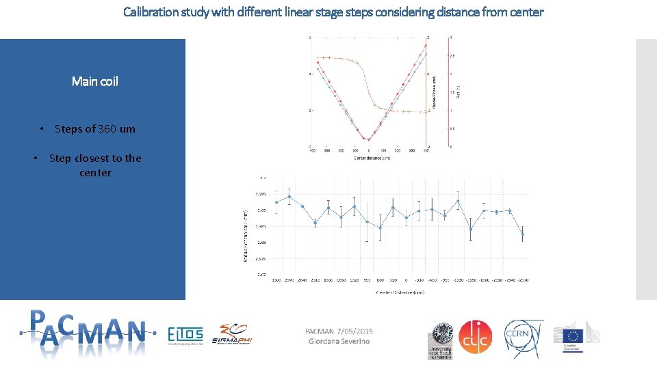
Calibration study with different linear stage steps considering distance from center Main coil • Steps of 360 um • Step closest to the center
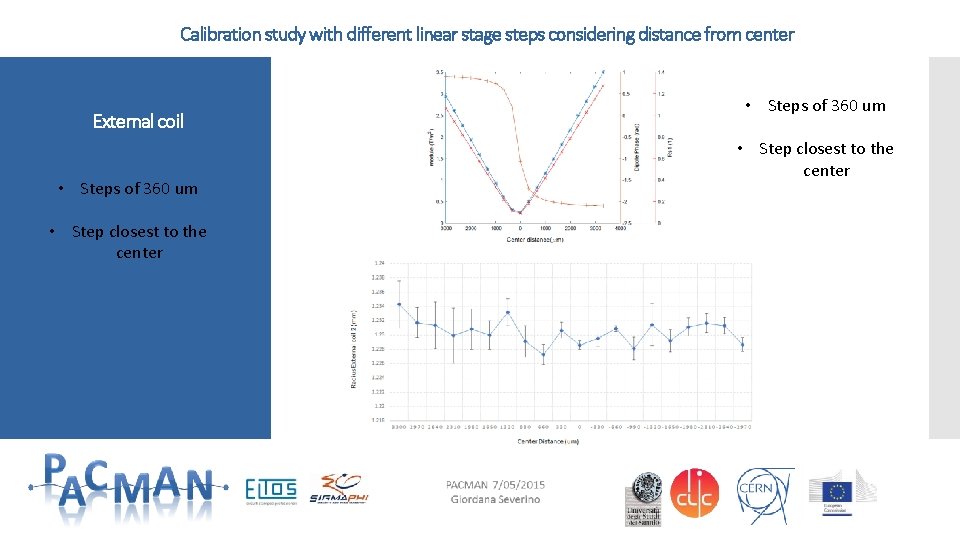
Calibration study with different linear stage steps considering distance from center External coil • Steps of 360 um • Step closest to the center
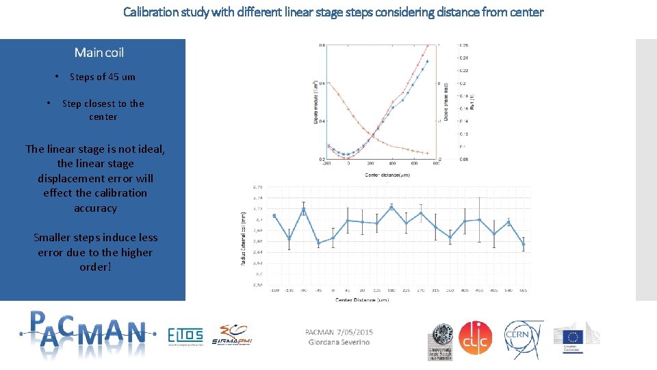
Calibration study with different linear stage steps considering distance from center • • Steps of 45 um Step closest to the center The linear stage is not ideal, the linear stage displacement error will effect the calibration accuracy Smaller steps induce less error due to the higher order!
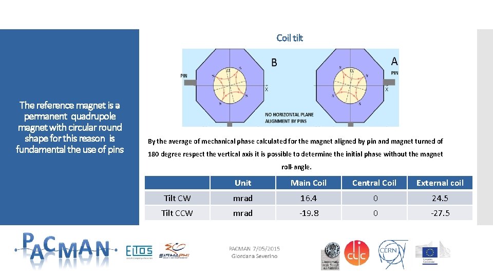
Coil tilt The reference magnet is a permanent quadrupole magnet with circular round shape for this reason is fundamental the use of pins • By the average of mechanical phase calculated for the magnet aligned by pin and magnet turned of 180 degree respect the vertical axis it is possible to determine the initial phase without the magnet roll-angle. Unit Main Coil Central Coil External coil Tilt CW mrad 16. 4 0 24. 5 Tilt CCW mrad -19. 8 0 -27. 5
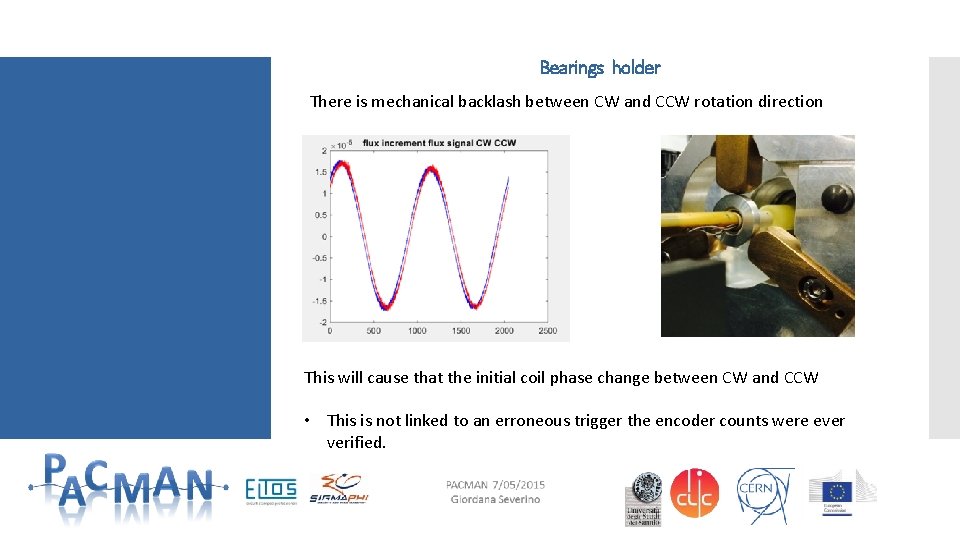
Bearings holder There is mechanical backlash between CW and CCW rotation direction This will cause that the initial coil phase change between CW and CCW • This is not linked to an erroneous trigger the encoder counts were ever verified.
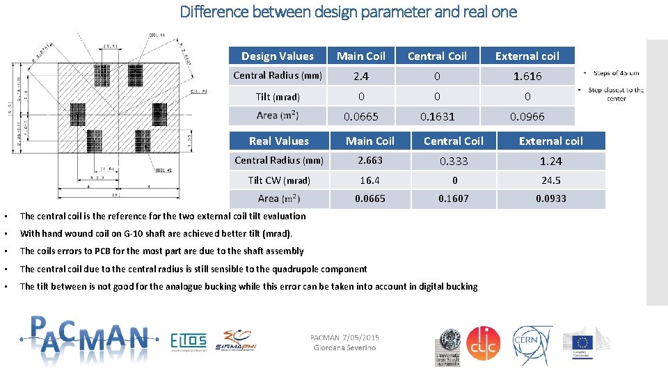
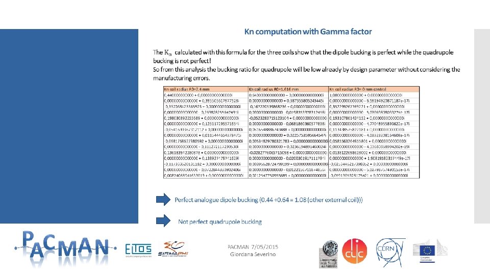
Difference between design parameter and real one Design Values Main Coil Central Coil External coil Central Radius (mm) 2. 4 0 1. 616 Tilt (mrad) 0 0. 0665 0. 1631 0. 0966 Real Values Main Coil Central Coil External coil Central Radius (mm) 2. 663 0. 333 1. 24 Tilt CW (mrad) 16. 4 0 24. 5 0. 0665 0. 1607 0. 0933 • The central coil is the reference for the two external coil tilt evaluation • With hand wound coil on G-10 shaft are achieved better tilt (mrad). • The coils errors to PCB for the most part are due to the shaft assembly • The central coil due to the central radius is still sensible to the quadrupole component • The tilt between is not good for the analogue bucking while this error can be taken into account in digital bucking
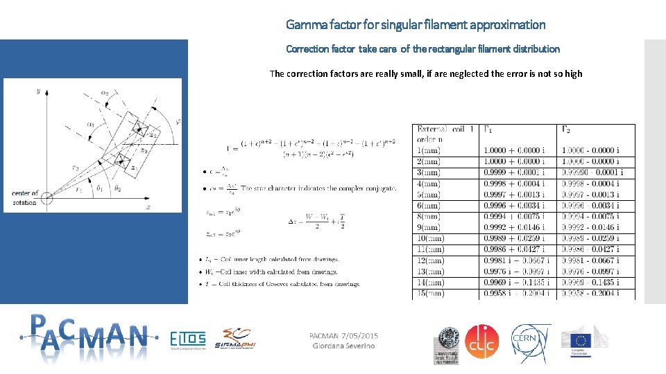
Gamma factor for singular filament approximation Correction factor take care of the rectangular filament distribution The correction factors are really small, if are neglected the error is not so high
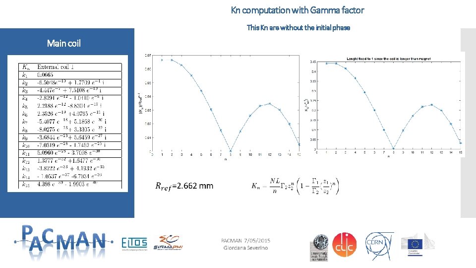
Kn computation with Gamma factor This Kn are without the initial phase Main coil
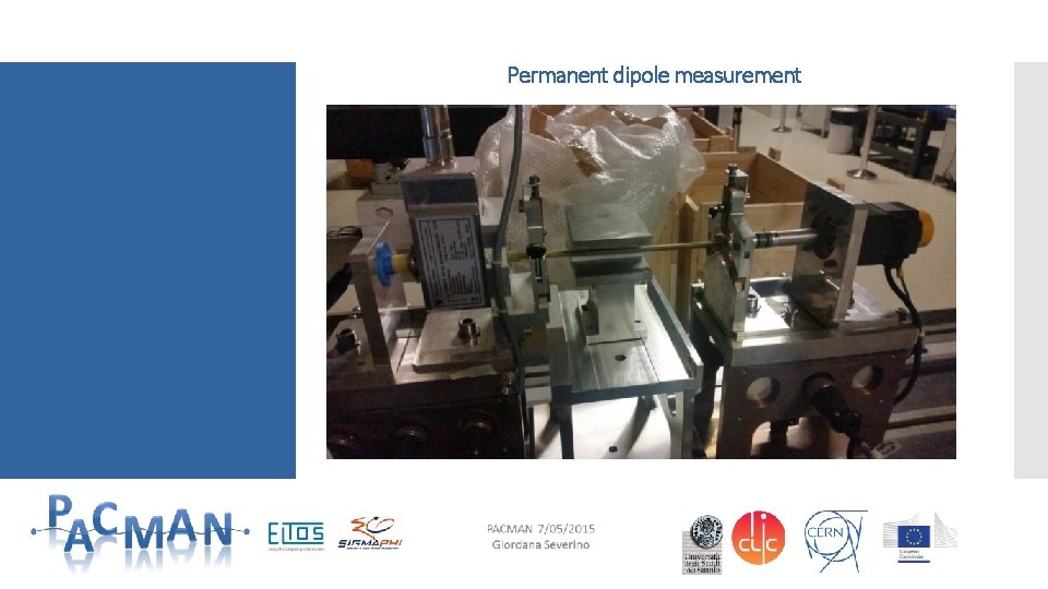
Permanent dipole measurement
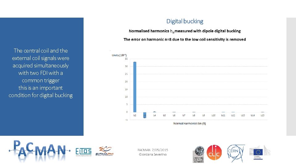
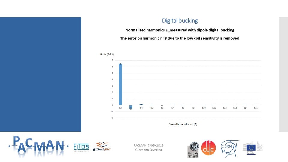
The central coil and the external coil signals were acquired simultaneously with two FDI with a common trigger this is an important condition for digital bucking
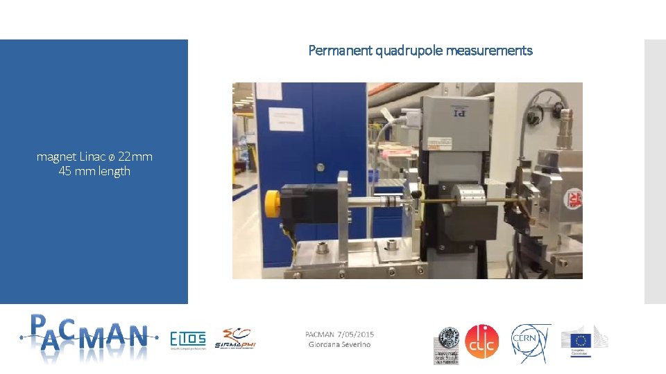
Permanent quadrupole measurements magnet Linac ø 22 mm 45 mm length
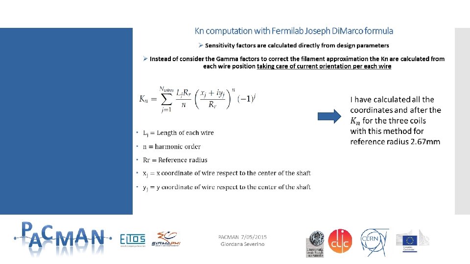
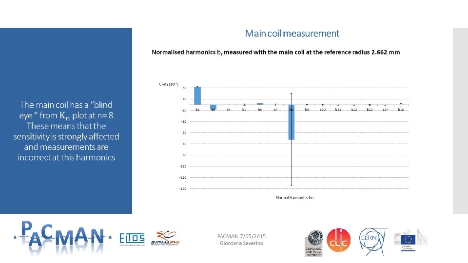
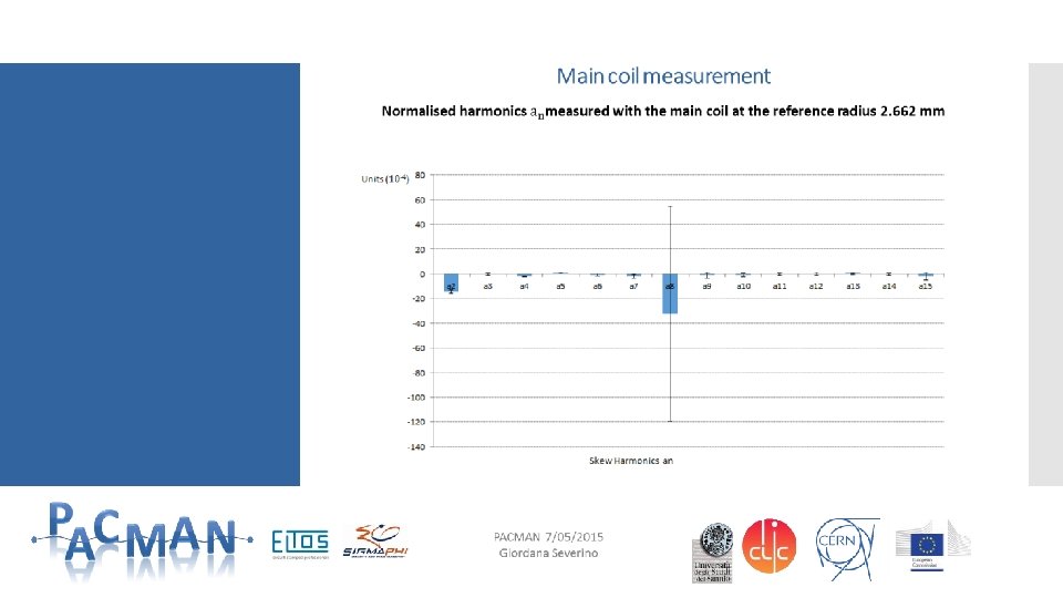
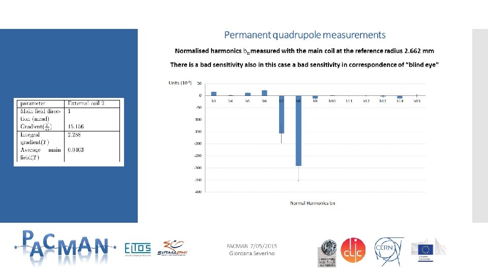
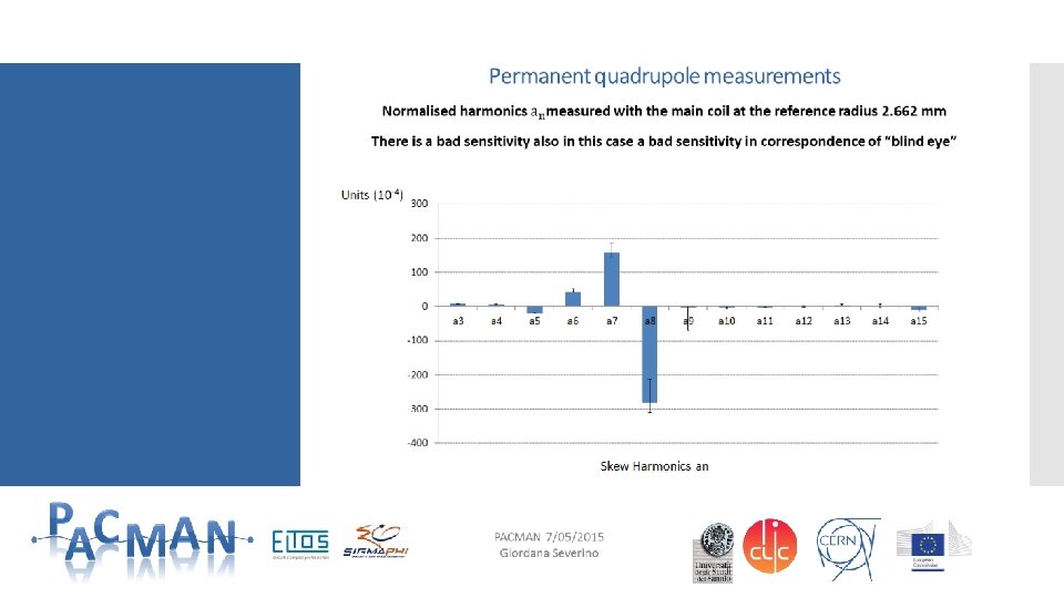
Permanent quadrupole measurements The value of the first harmonics are still to much high for the radius of reference considered so it is necessary to do the bucking to see the real values without vibration and torsion Next step will be to compare measurements done with digital bucking using three FDI To compare the results will be done the same measurement with the 20 mm shaft diameter rotating coil system and will be done an extrapolation for the values at radius of reference 2. 662 mm Compare results obtained with Kn calculated by Fermilab formula
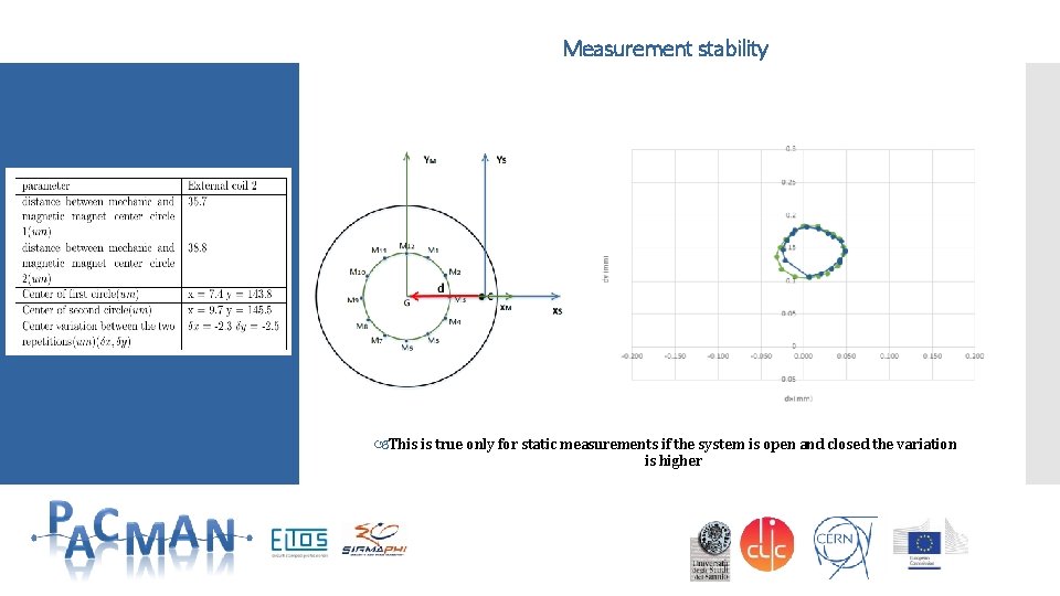
Measurement stability This is true only for static measurements if the system is open and closed the variation is higher
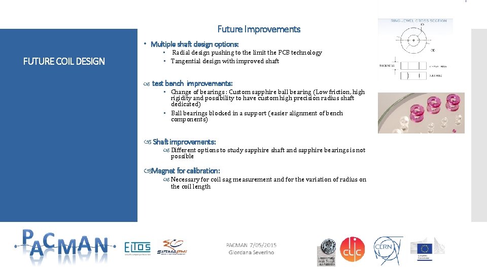
Future Improvements • Multiple shaft design options: FUTURE COIL DESIGN • Radial design pushing to the limit the PCB technology • Tangential design with improved shaft test bench improvements: • Change of bearings : Custom sapphire ball bearing (Low friction, high rigidity and possibility to have custom high precision radius shaft dedicated) • Ball bearings blocked in a support (easier alignment of bench components) Shaft improvements: Different options to study sapphire shaft and sapphire bearings is not possible Magnet for calibration: Necessary for coil sag measurement and for the variation of radius on the coil length
Thank you for your attention Presentation 7/05/2015