ELECTRONIC CIRCUIT Practical Voltage Source Practical Current Source


 A circuit containing three nodes and five branches. (b) Node 1 is redrawn")


 Series combination of N resistors. (b) Electrically equivalent circuit.")


 voltage")
 Series connected voltage sources can be replaced by a single source. (b) Parallel")

 voltage")


 Insert Figure 4. 20")


- Slides: 47
ELECTRONIC CIRCUIT
Practical Voltage Source
Practical Current Source
Circuit Topology Fundamental
Definition of a branch
Definitions of node and supernode
(a) A circuit containing three nodes and five branches. (b) Node 1 is redrawn to look like two nodes; it is still one node.
Definition of a loop Definition of a mesh
Series Circuits and Kirchhoff’s Voltage Law
Voltage Relationships: Kirchhoff’s Voltage Law • Kirchhoff’s Voltage Law – The sum of the component voltages in a series circuit must equal the source voltage 1840 – German Physicist, Gustav Kirchhoff – Actual wording – The algebraic sum of the voltages around a closed loop is zero – The following equation takes polarity into account
Kirchhoff’s Voltage Law, • Example: VS = +10 V, V 1 = +2 V, V 2 = +8 V
Series Circuit Characteristics • Series Circuit – a circuit that contains only one current path
(a) Series combination of N resistors. (b) Electrically equivalent circuit.
Series Circuit Characteristics • Total Series Resistance where RT = the total circuit resistance Rn = the highest-numbered resistor in the circuit
Series Circuit Characteristics • Current Characteristics – the current at any point in a series circuit must equal the current at every other point in the circuit Insert Figure 4. 5
Series Circuit Characteristics • Voltage Characteristics where VS = the source (or total) voltage Vn = the voltage across the highest numbered resistor in the circuit
(a) Series connected voltage sources can be replaced by a single source. (b) Parallel current sources can be replaced by a single source.
Examples of circuits with multiple sources, some of which are “illegal” as they violate Kirchhoff’s laws.
Series Circuit Characteristics • Power Characteristics where PS = the source (or total) voltage Pn = the power that is dissipated across the highest numbered resistor in the circuit
Series Circuit Characteristics Insert Figure 4. 10
Voltage References • Voltage References - Circuits have a point that serves as the 0 V reference (ground) Insert Figure 4. 12
Voltage Divider • The Voltage Divider Relationship – Voltage Divider – often used to analyze a series circuit where Rn = the resistor of interest Vn = the voltage drop across Rn (where n is the component number)
We may find v 2 by applying KVL and Ohm’s law: so An illustration of voltage division. Thus, or For a string of N series resistors, we may write:
• Source Resistance: A Practical Consideration – Ideal Voltage Source – maintains a constant output voltage regardless of the resistance of its load – Real Voltage Source – internal resistance causes a decrease in load resistance results in a decrease in the source voltage
• Source Resistance: A Practical Consideration (Continued) Insert Figure 4. 20
Maximum Power Transfer Theorem • maximum power transfer from a voltage source to its load occurs when the load resistance is equal to the source resistance
Series-Connected Voltage Sources • Series-Aiding Voltage Sources – the total voltage equals the sum of the voltages • Series-Opposing Voltage Sources – the total voltage equals the difference of the voltages
Earth Ground Versus Chassis Ground Insert Figure 4. 28
Parallel Circuits and Kirchholf’s Current Law
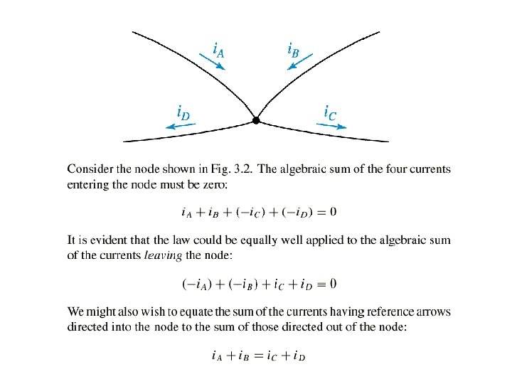
Current Relationships: Kirchhoff’s Current • Kirchhoff’s Current Law: Law – The algebraic sum of the currents entering and leaving a point must equal zero – In other words, the total current leaving a point must equal the total current entering that point i 2 i 1 i 3
Parallel Circuit Characteristics • Parallel Circuit – a circuit that provides more than one current path between any two points Insert Figure 5. 1
Parallel Circuit Characteristics • Current Characteristics where In = the current through the highest-numbered branch in the circuit
Parallel Circuit Characteristics • Voltage and Current Values – Voltage across each component is equal – Current through each branch is determined by the source voltage and the resistance of the branch.
Parallel Circuit Characteristics • Resistance Characteristics – the total circuit resistance is always lower than any of the branch resistance values Insert Figure 5. 5
Parallel Circuit Characteristics • Power Characteristics – Total Power – sum of the power dissipation values for the individual components – The lower value of the branch resistance, the higher percentage of the total power it dissipates (opposite that of series circuits)
Parallel Circuit Characteristics Insert Figure 5. 6
Example: Beginning with a simple KCL equation, or Thus, A special case worth remembering is (a) A circuit with N resistors in parallel. (b) Equivalent circuit.
Parallel Resistance Relationships • Calculating Total Resistance: The Product. Over-Sum Method
Current Sources • a source that is designed to provide an output current value that remains relatively constant over a wide range of load resistance values Insert Figure 5. 12
Current Dividers • Current Dividers – the source current is divided among the branches
The current flowing through R 2 is or An illustration of current division. For a parallel combination of N resistors, the current through Rk is
Practical Current Sources: • The Effects of Source Resistance – Ideal Current Source – constant current and infinite internal resistance – Real Current Source – current varies for a change in load resistance and internal resistance is not infinite – Internal resistance is usually much greater than the load resistance
Series-Parallel Circuits
Series-Parallel Circuits • Connecting Series Circuits in Parallel Insert Figure 6. 3
Series-Parallel Circuits • Connecting Parallel Circuits in Series Insert Figure 6. 5
Analyzing Series-Parallel Circuits