Introduction qa voltage controlled voltage source with very


 Inverting amplifier (c) Differential amplifier (b) Non-inverting amplifier (d) Summing")


- Slides: 18
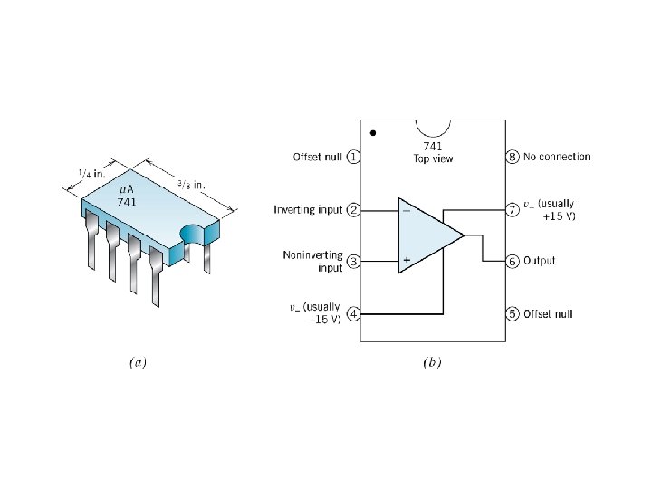
Introduction qa voltage controlled voltage source with very high gain. qfive terminals four ports active element. q. In+Ip+Ic++Ic-+Io=0 Equivalent circuit model of op-amp Vi=Vp-Vn. Ri is the input resistance Ro is the output resistance Vo=AVi=A(Vp-Vn)
Voltage Transfer Curve In reality A, Ri are finite and Ro>0 The output is limited by power source For a 741 op-amp powered with VCC= +10 V and VEE= -10 V, Vo will saturate (reach the maximum output voltage range) at about ± 10 V. With an A=200, 000 V/V saturation occurs with an input differential voltage of 10/200, 000 = 50μV, a very small voltage. How to use it in circuits?
Negative Feedback
Ideal op-amp model Ideal op-amp conditions: Ip=In=0 No current into the terminals Ri=∞ Infinite input resistance Ro=0 Zero output resistance A ∞ Infinite open loop gain Ip=In=0 and Ri=∞ makes no power demands on the input signal source. Ro=0 makes the output voltage independent of the load. Even though the ideal op-amp model deviates much from the real op-amps, the ideal conditions in the ideal op-amp model are very useful in the design and analysis of circuits.
Fundamental Amplifier Configurations (a) Inverting amplifier (c) Differential amplifier (b) Non-inverting amplifier (d) Summing amplifier
Inverting Amplifier— Ideal op-amp circuit analysis Ideal op-amp conditions: Ip=In=0 Ri=∞ Ro=0 A ∞ No current into the terminals Infinite input resistance Zero output resistance Infinite open loop gain
Non-Inverting Amplifier: Ideal op-amp circuit analysis Ideal op-amp conditions: Ip=In=0 Ri=∞ Ro=0 A ∞ No current into the terminals Infinite input resistance Zero output resistance Infinite open loop gain
The Voltage Follower Purpose ?
Inverting Amplifier — Effect of Finite Open-Loop Gain The current through R 1 is now Considering I 1=I 2, the output voltage Vo can thus be determined from
Inverting Amplifier — Effect of Finite Open-Loop Gain Let’s consider an inverting amplifier design with R 1=10 kΩ and R 2=100 kΩ. In this case, the ideal voltage gain is -10. By assuming that A ranges in values from 1, 000 V/V to 10, 000 V/V, Table I shows the real gain and the resulting deviation in % from the ideal case
Non-Inverting Amplifier — Effect of Finite Open-Loop Gain Since In=Ip=0, we have I 1=I 2 and therefore Since the voltage Vi = Vp-Vn = Vin-Vn, the output voltage is given by
Differential Amplifier: Ideal op-amp circuit analysis The output voltage is In order to obtain Vout=0 when Vin 1=Vin 2 only if System is linear and so we may apply superposition Which holds only if The contribution of the signal Vin 2 to the output is The output voltage is now The contribution of the signal Vin 1 to the output is
Real Op-Amp Frequency Response Real Op amps have a frequency dependant open loop gain Where
Real Op-Amp Frequency Response If the open loop bandwidth is so small, how can the op amp be useful?
Real Op-Amp Frequency Response Closed loop band width:
Real Op-Amp Frequency Response
Real Op-Amp Frequency Response Closed loop band width: