ELECTROCHEMICAL SYSTEMS FOR ELECTRIC POWER GENERATION Dzmitry Malevich

- Slides: 29
ELECTROCHEMICAL SYSTEMS FOR ELECTRIC POWER GENERATION Dzmitry Malevich Depatrment of Chemistry and Biochemistry University of Guelph
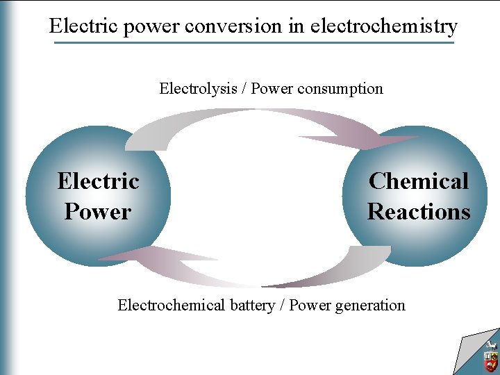
Electric power conversion in electrochemistry Electrolysis / Power consumption Electric Power Chemical Reactions Electrochemical battery / Power generation
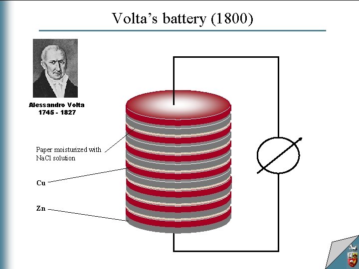
Volta’s battery (1800) Alessandro Volta 1745 - 1827 Paper moisturized with Na. Cl solution Cu Zn
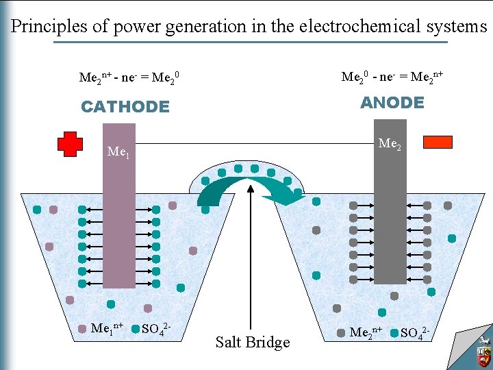
Principles of power generation in the electrochemical systems Me 20 - ne- = Me 2 n+ - ne- = Me 20 ANODE CATHODE Me 2 Me 1 n+ SO 42 - Salt Bridge Me 2 n+ SO 42 -
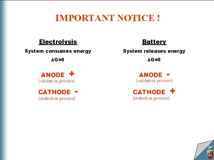
IMPORTANT NOTICE ! Electrolysis Battery System consumes energy System releases energy G>0 G<0 ANODE + (oxidation process) CATHODE - (reduction process) ANODE - (oxidation process) CATHODE + (reduction process)
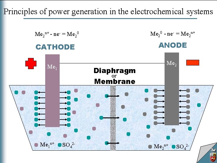
Principles of power generation in the electrochemical systems Me 20 - ne- = Me 2 n+ - ne- = Me 20 ANODE CATHODE Me 1 n+ Diaphragm or Membrane SO 42 - Me 2 n+ SO 42 -
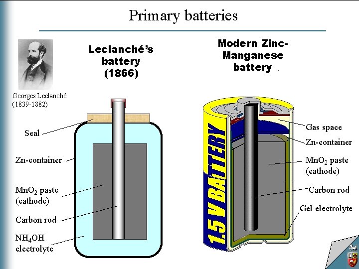
Primary batteries Modern Zinc. Manganese battery Leclanché’s battery (1866) Georges Leclanché (1839 -1882) Seal Zn-container Mn. O 2 paste (cathode) Carbon rod NH 4 OH electrolyte Anode: Zn 2+ + 2 e. Cathode: 2 Mn. O 2 + 2 H 2 O +2 e- 2 Mn. OOH + 2 OH- Gas space Electrolyte: Zn 2+ 2 NH 4 Cl +2 OH- Zn(NH 3)Cl 2 + 2 H 2 O Zn-container 2 Mn. O 2 + Zn + 2 NH 4 Cl 2 Mn. OOH + Zn(NH 3)Cl 2 Mn. O 2 paste (cathode) Carbon rod Gel electrolyte
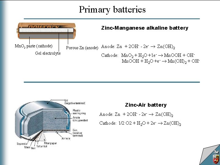
Primary batteries Zinc-Manganese alkaline battery Mn. O 2 paste (cathode) Gel electrolyte Porous Zn (anode) Anode: Zn + 2 OH - 2 e Zn(OH)2 Cathode: Mn. O 2 + H 2 O +1 e- Mn. OOH + OHaaaaa Mn. OOH + H 2 O +e- Mn(OH)2 + OH- Zinc-Air battery Anode: Zn + 2 OH- - 2 e- Zn(OH)2 Cathode: 1/2 O 2 + H 2 O + 2 e- Zn(OH)2
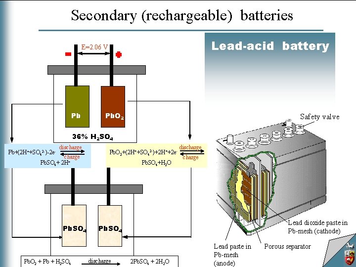
Secondary (rechargeable) batteries Lead-acid battery Lead-acid E=2. 06 V Pb Pb. O 2 Safety valve 36% H 2 SO 4 Pb+(2 H++SO 42 -)-2 e- discharge Pb. SO 4+ 2 H+ Pb. SO 4 Pb. O 2 + Pb + H 2 SO 4 Pb. O 2+(2 H++SO 42 -)+2 H++2 e. Pb. SO 4+H 2 O discharge Lead dioxide paste in Pb-mesh (cathode) Pb. SO 4 discharge 2 Pb. SO 4 + 2 H 2 O Lead paste in Pb-mesh (anode) Porous separator
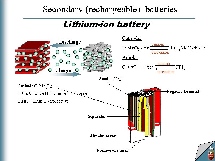
Secondary (rechargeable) batteries Lithium-ion battery Cathode: Discharge Li. Me. O 2 - xe- CHARGE DISCHARGE Li 1 -x. Me. O 2 + x. Li+ Anode: C + x. Li+ + xe- Charge CHARGE DISCHARGE CLix Anode (CLix) Cathode (Li. Mex. Oy) Negative terminal Li. Co. O 2 -utilized for commercial batteries Li. Ni. O 2, Li. Mn 2 O 4 -prospective Separator Aluminum can Positive terminal
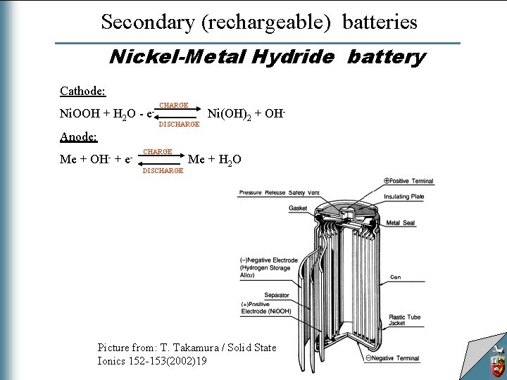
Secondary (rechargeable) batteries Nickel-Metal Hydride battery Cathode: Ni. OOH + H 2 O - e- CHARGE DISCHARGE Ni(OH)2 + OH- Anode: Me + OH- + e- CHARGE DISCHARGE Me + H 2 O Picture from: T. Takamura / Solid State Ionics 152 -153(2002)19
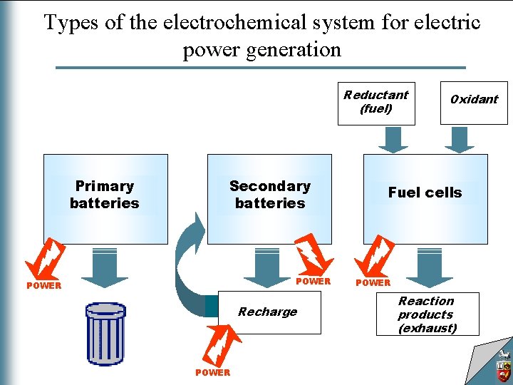
Types of the electrochemical system for electric power generation Reductant (fuel) Primary batteries Secondary batteries POWER Recharge POWER Oxidant Fuel cells POWER Reaction products (exhaust)
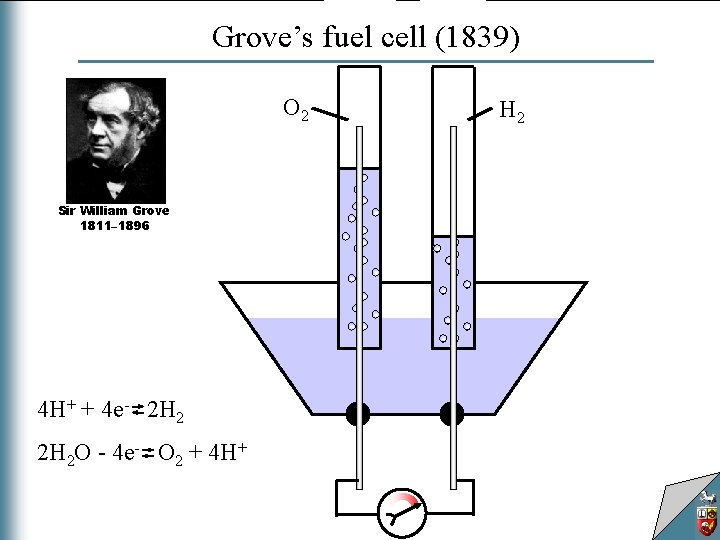
Grove’s fuel cell (1839) O 2 Sir William Grove 1811– 1896 4 H+ + 4 e- 2 H 2 O - 4 e- O 2 + 4 H+ H 2
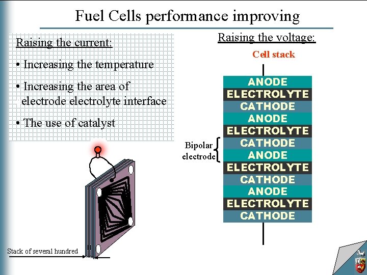
Fuel Cells performance improving Raising the voltage: Raising the current: Connection of cells Cell stackin series • Increasing the temperature • Increasing the area of eelectrode electrolyte interface • The use of catalyst Cathode catalyst Anode catalyst Bipolar electrode H 2 O 2 Stack of several hundred Electrolyte frame Bipolar plate ANODE ELECTROLYTE CATHODE ANODE ELECTROLYTE ANODE CATHODE ELECTROLYTE CATHODE ANODE ELECTROLYTE CATHODE
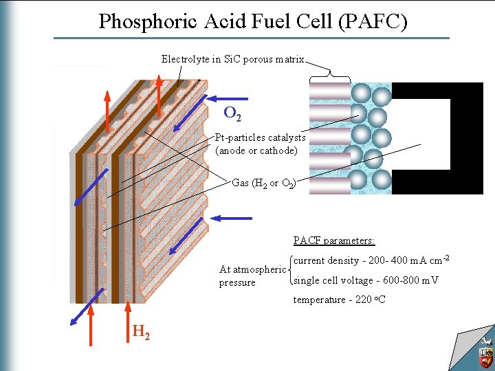
Phosphoric Acid Fuel Cell (PAFC) Electrolyte in Si. C porous matrix O 2 Pt-particles catalysts (anode or cathode) Gas (H 2 or O 2) PACF parameters: current density - 200 - 400 m. A cm-2 At atmospheric single cell voltage - 600 -800 m. V pressure temperature - 220 o. C H 2
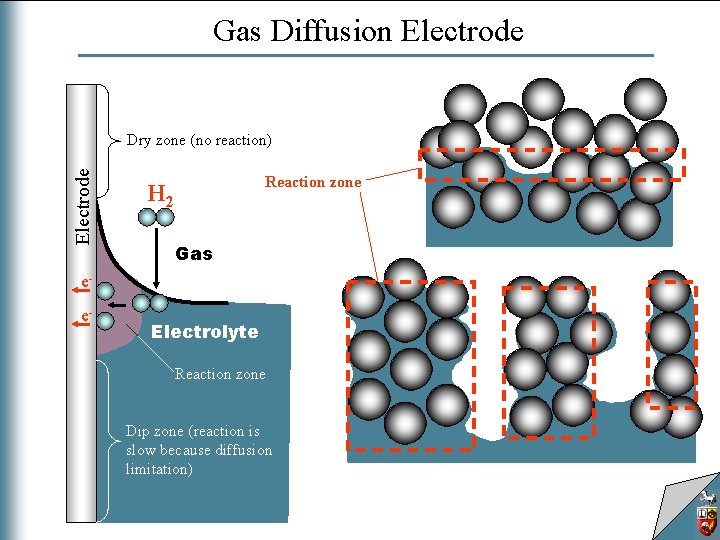
Gas Diffusion Electrode Dry zone (no reaction) Reaction zone H 2 Gas ee- Electrolyte Reaction zone Dip zone (reaction is slow because diffusion limitation)
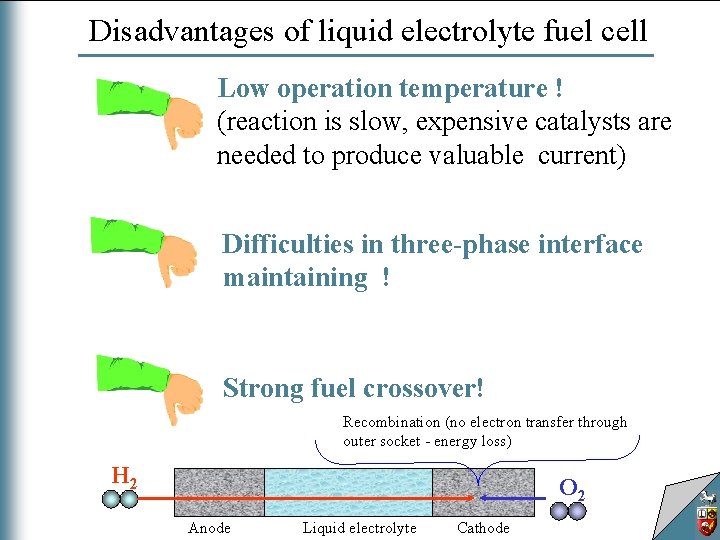
Disadvantages of liquid electrolyte fuel cell Low operation temperature ! (reaction is slow, expensive catalysts are needed to produce valuable current) Difficulties in three-phase interface maintaining ! Strong fuel crossover! Recombination (no electron transfer through outer socket - energy loss) H 2 O 2 Anode Liquid electrolyte Cathode
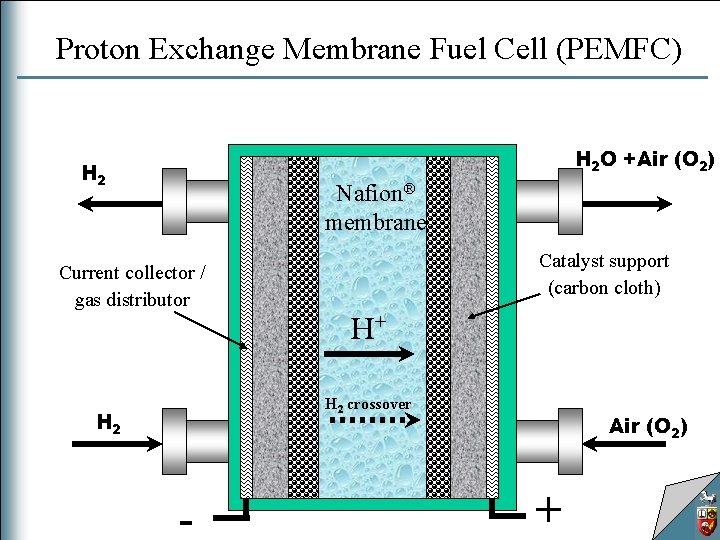
Proton Exchange Membrane Fuel Cell (PEMFC) H 2 O +Air (O 2) H 2 Nafion® membrane Current collector / gas distributor Catalyst support (carbon cloth) H+ H 2 crossover H 2 - Air (O 2) +
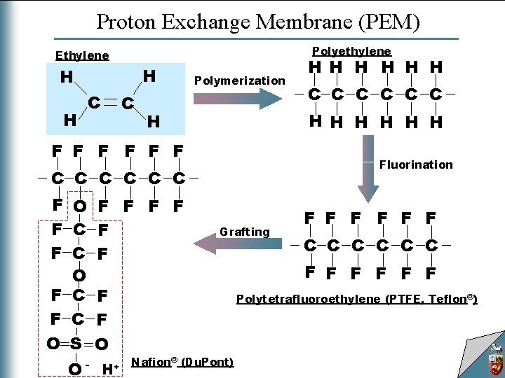
Proton Exchange Membrane (PEM) Polyethylene Ethylene H H H C C Polymerization F F F Fluorination C C C O - H+ C C C H H H H F O F F F C F O S O H H H Grafting Nafion® (Du. Pont) F F F C C C F F F Polytetrafluoroethylene (PTFE, Teflon®)
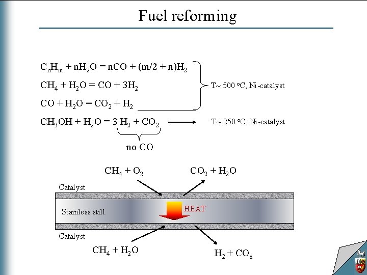
Fuel reforming Cn. Hm + n. H 2 O = n. CO + (m/2 + n)H 2 CH 4 + H 2 O = CO + 3 H 2 T~ 500 o. C, Ni-catalyst CO + H 2 O = CO 2 + H 2 CH 3 OH + H 2 O = 3 H 2 + CO 2 T~ 250 o. C, Ni-catalyst no CO CH 4 + O 2 CO 2 + H 2 O Catalyst Stainless still HEAT Catalyst CH 4 + H 2 O H 2 + COx
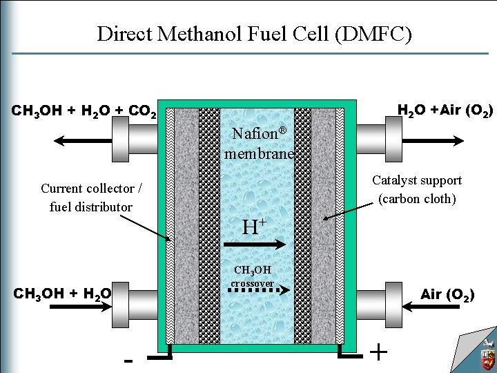
Direct Methanol Fuel Cell (DMFC) H 2 O +Air (O 2) CH 3 OH + H 2 O + CO 2 Nafion® membrane Current collector / fuel distributor Catalyst support (carbon cloth) H+ CH 3 OH crossover CH 3 OH + H 2 O - Air (O 2) +
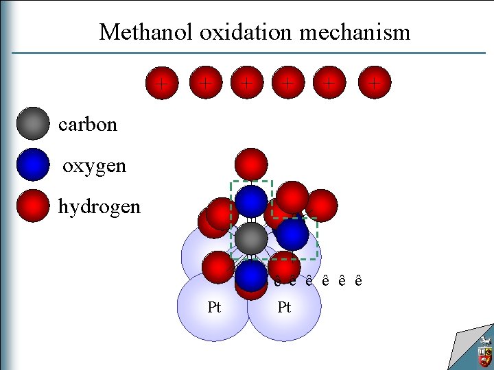
Methanol oxidation mechanism + + + carbon oxygen hydrogen ê ê ê Pt Pt +
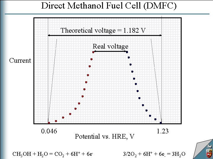
Direct Methanol Fuel Cell (DMFC) Theoretical voltage = 1. 182 V Real voltage Current 0. 046 Potential vs. HRE, V CH 3 OH + H 2 O = CO 2 + 6 H+ + 6 e- 1. 23 3/2 O 2 + 6 H+ + 6 e- = 3 H 2 O
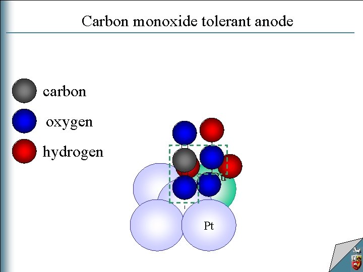
Carbon monoxide tolerant anode carbon oxygen hydrogen Ru Pt
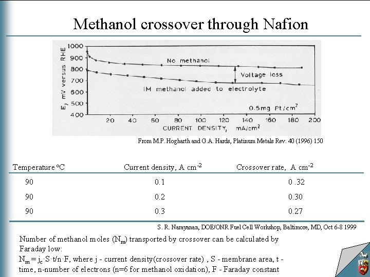
Methanol crossover through Nafion From M. P. Hogharth and G. A. Hards, Platinum Metals Rev. 40 (1996) 150 Temperature o. C Current density, A cm-2 Crossover rate, A cm-2 90 0. 1 0. 32 90 0. 2 0. 30 90 0. 3 0. 27 S. R. Narayanan, DOE/ONR Fuel Cell Workshop, Baltimore, MD, Oct 6 -8 1999 Number of methanol moles (Nm) transported by crossover can be calculated by Faraday low: Nm = jc·S·t/n·F, where j - current density(crossover rate) , S - membrane area, t time, n-number of electrons (n=6 for methanol oxidation), F - Faraday constant
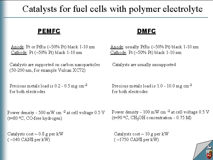
Catalysts for fuel cells with polymer electrolyte PEMFC Anode: Pt or Pt. Ru (~50% Pt) black 1 -10 nm Cathode: Pt (~50% Pt) black 1 -10 nm DMFC Anode: usually Pt. Ru (~50% Pt) black 1 -10 nm Cathode: Pt (~50% Pt) black 1 -10 nm Catalysts are supported on carbon nanoparticles (50 -200 nm, for example Vulcan XC 72) Catalysts are usually unsupported Precious metals load is 0. 2 - 0. 5 mg cm-2 for both electrodes Precious metals load is 1. 0 - 10. 0 mg cm-2 for both electrodes Power density - 500 m. W cm -2 at cell voltage 0. 5 V (t=80 o. C, CO-free hydrogen) Catalysts cost ~ 0. 8 g per k. W ( ~140 CAN$ per k. W) Power density - 100 m. W cm -2 at cell voltage 0. 5 V (t=90 o. C, CH 3 OH concentration - 0. 75 M) Catalysts cost ~ 10 g per k. W ( ~1750 CAN$ per k. W)
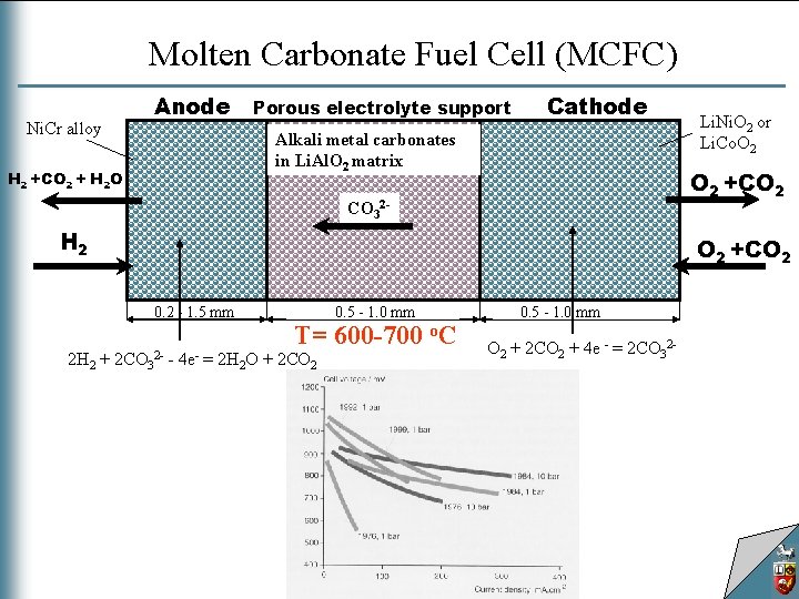
Molten Carbonate Fuel Cell (MCFC) Anode Ni. Cr alloy Porous electrolyte support Cathode Alkali metal carbonates in Li. Al. O 2 matrix H 2 +CO 2 + H 2 O O 2 +CO 2 CO 32 - H 2 O 2 +CO 2 0. 2 - 1. 5 mm 2 H 2 + Li. Ni. O 2 or Li. Co. O 2 2 CO 32 - - 4 e- 0. 5 - 1. 0 mm T= 600 -700 o. C = 2 H 2 O + 2 CO 2 0. 5 - 1. 0 mm O 2 + 2 CO 2 + 4 e - = 2 CO 32 -
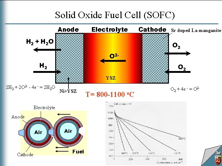
Solid Oxide Fuel Cell (SOFC) Anode Electrolyte H 2 + H 2 O Cathode Sr doped La-manganite O 2 - H 2 O 2 YSZ 2 H 2 + 2 O 2 - - 4 e - = 2 H 2 O Ni+YSZ Electrolyte Anode Air Cathode Air Fuel T= 800 -1100 o. C O 2 + 4 e - = O 2 -
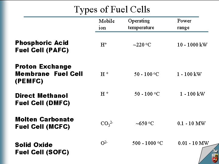
Types of Fuel Cells Mobile ion Operating temperature Power range Phosphoric Acid Fuel Cell (PAFC) H+ ~220 o. C 10 - 1000 k. W Proton Exchange Membrane Fuel Cell (PEMFC) H+ 50 - 100 o. C 1 - 100 k. W H+ 50 - 100 o. C CO 32 - ~650 o. C Direct Methanol Fuel Cell (DMFC) Molten Carbonate Fuel Cell (MCFC) Solid Oxide Fuel Cell (SOFC) O 2 - 500 - 1000 o. C 1 - 100 k. W 0. 1 - 10 MW 0. 01 - 10 MW