E 85 Digital Design Computer Engineering Lecture 20
- Slides: 52
E 85 Digital Design & Computer Engineering Lecture 20: Single Cycle Processor Controller
Lecture 20 • Single Cycle Processor Controller Digital Design and Computer Architecture: ARM® Edition © 2015 Lecture 20 <2>
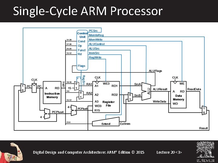
Single-Cycle ARM Processor Digital Design and Computer Architecture: ARM® Edition © 2015 Lecture 20 <3>
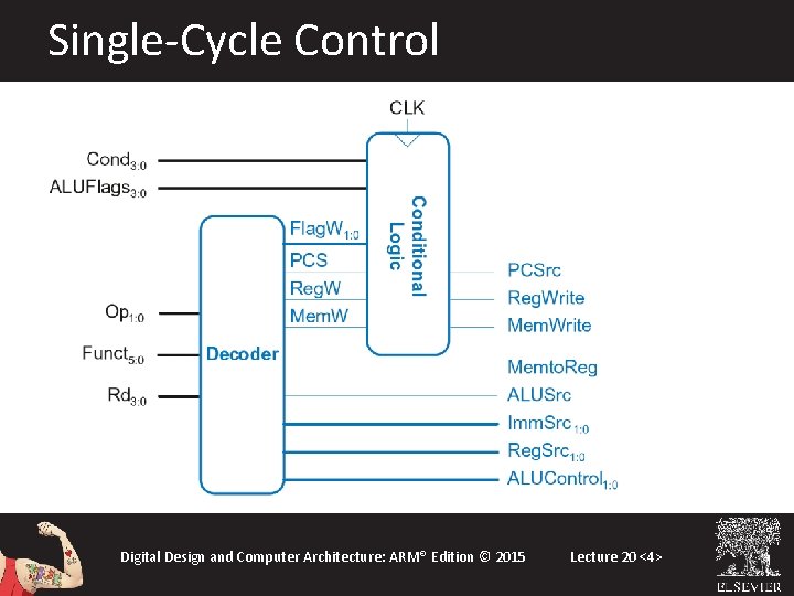
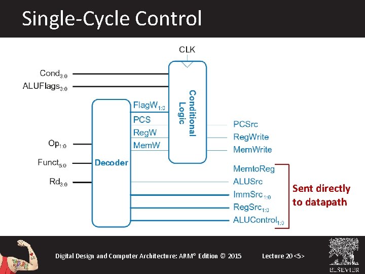
Single-Cycle Control Digital Design and Computer Architecture: ARM® Edition © 2015 Lecture 20 <4>
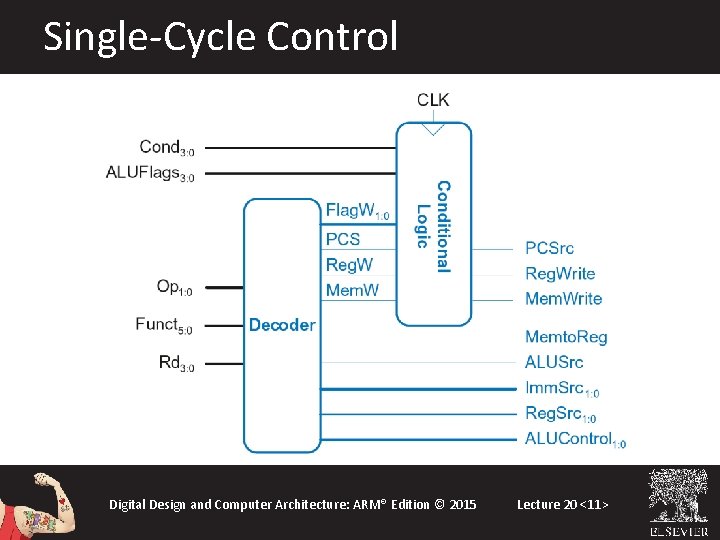
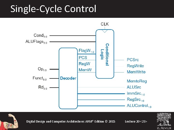
Single-Cycle Control Sent directly to datapath Digital Design and Computer Architecture: ARM® Edition © 2015 Lecture 20 <5>
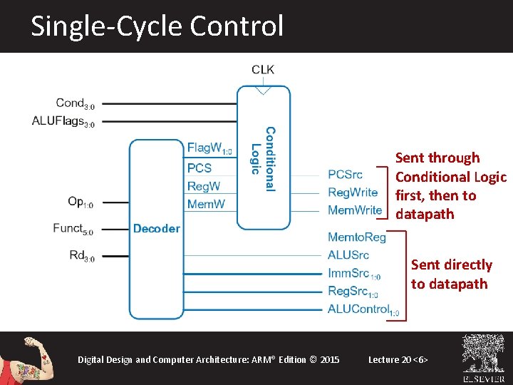
Single-Cycle Control Sent through Conditional Logic first, then to datapath Sent directly to datapath Digital Design and Computer Architecture: ARM® Edition © 2015 Lecture 20 <6>
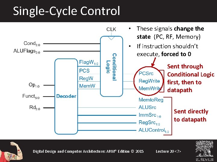
Single-Cycle Control • These signals change the state (PC, RF, Memory) • If instruction shouldn’t execute, forced to 0 Sent through Conditional Logic first, then to datapath Sent directly to datapath Digital Design and Computer Architecture: ARM® Edition © 2015 Lecture 20 <7>
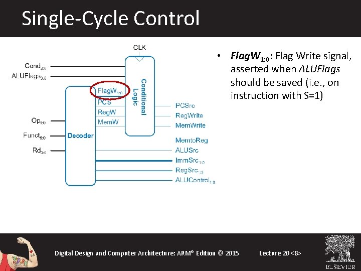
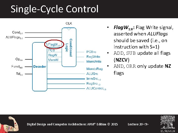
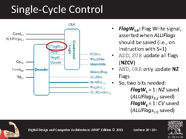
Single-Cycle Control • Flag. W 1: 0: Flag Write signal, asserted when ALUFlags should be saved (i. e. , on instruction with S=1) Digital Design and Computer Architecture: ARM® Edition © 2015 Lecture 20 <8>
Single-Cycle Control • Flag. W 1: 0: Flag Write signal, asserted when ALUFlags should be saved (i. e. , on instruction with S=1) • ADD, SUB update all flags (NZCV) • AND, ORR only update NZ flags Digital Design and Computer Architecture: ARM® Edition © 2015 Lecture 20 <9>
Single-Cycle Control • Flag. W 1: 0: Flag Write signal, asserted when ALUFlags should be saved (i. e. , on instruction with S=1) • ADD, SUB update all flags (NZCV) • AND, ORR only update NZ flags • So, two bits needed: Flag. W 1 = 1: NZ saved (ALUFlags 3: 2 saved) Flag. W 0 = 1: CV saved (ALUFlags 1: 0 saved) Digital Design and Computer Architecture: ARM® Edition © 2015 Lecture 20 <10>
Single-Cycle Control Digital Design and Computer Architecture: ARM® Edition © 2015 Lecture 20 <11>
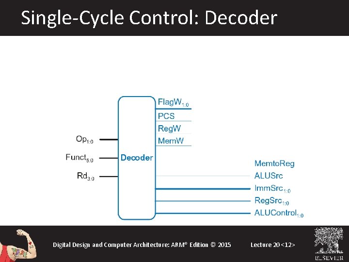
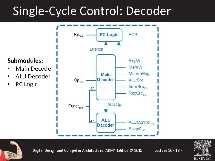
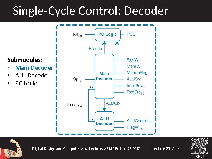
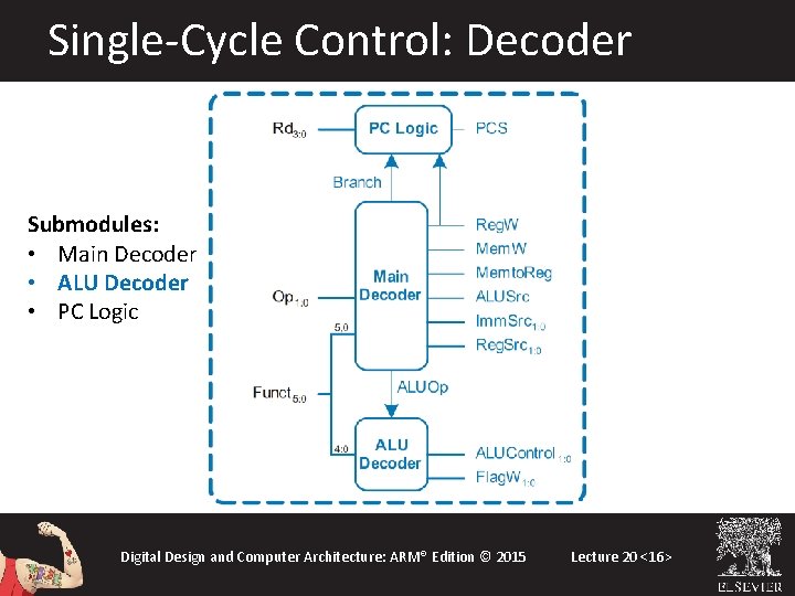
Single-Cycle Control: Decoder Digital Design and Computer Architecture: ARM® Edition © 2015 Lecture 20 <12>
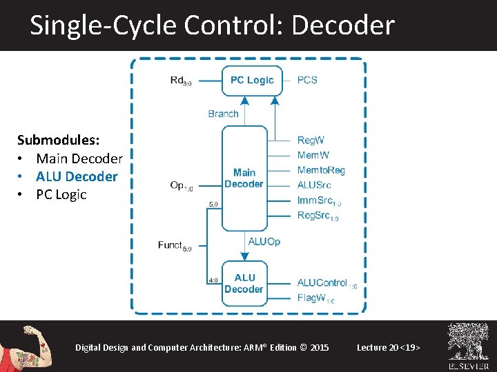
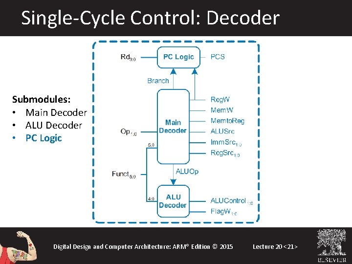
Single-Cycle Control: Decoder Submodules: • Main Decoder • ALU Decoder • PC Logic Digital Design and Computer Architecture: ARM® Edition © 2015 Lecture 20 <13>
Single-Cycle Control: Decoder Submodules: • Main Decoder • ALU Decoder • PC Logic Digital Design and Computer Architecture: ARM® Edition © 2015 Lecture 20 <14>
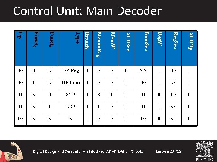
Control Unit: Main Decoder Mem. W ALUSrc X DP Reg 0 0 XX 1 00 1 X DP Imm 0 0 0 1 00 1 X 0 1 01 X 0 STR 0 X 1 1 01 0 10 0 01 X 1 LDR 0 1 01 1 X 0 0 10 X X B 1 0 0 1 10 0 X 1 0 Lecture 20 <15> ALUOp Memto. Reg. Src Branch 0 Digital Design and Computer Architecture: ARM® Edition © 2015 Reg. W Funct 0 Imm. Src Funct 5 Type Op 00
Single-Cycle Control: Decoder Submodules: • Main Decoder • ALU Decoder • PC Logic Digital Design and Computer Architecture: ARM® Edition © 2015 Lecture 20 <16>
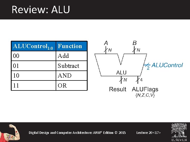
Review: ALUControl 1: 0 Function 00 Add 01 Subtract 10 AND 11 OR Digital Design and Computer Architecture: ARM® Edition © 2015 Lecture 20 <17>
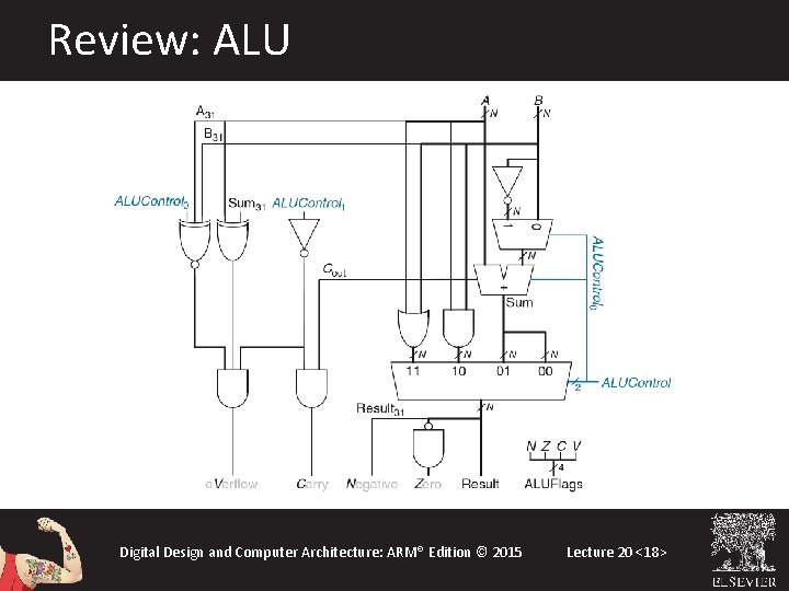
Review: ALU Digital Design and Computer Architecture: ARM® Edition © 2015 Lecture 20 <18>
Single-Cycle Control: Decoder Submodules: • Main Decoder • ALU Decoder • PC Logic Digital Design and Computer Architecture: ARM® Edition © 2015 Lecture 20 <19>
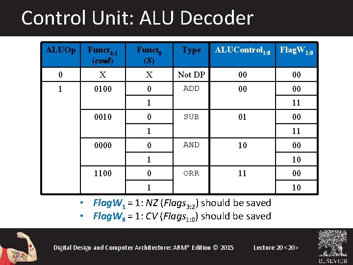
Control Unit: ALU Decoder ALUOp Funct 4: 1 (cmd) Funct 0 (S) Type ALUControl 1: 0 Flag. W 1: 0 0 X X Not DP 00 00 1 0100 0 ADD 00 00 1 0010 0 11 SUB 01 0000 0 11 AND 10 00 1 1100 0 10 ORR 11 00 1 10 • Flag. W 1 = 1: NZ (Flags 3: 2) should be saved • Flag. W 0 = 1: CV (Flags 1: 0) should be saved Digital Design and Computer Architecture: ARM® Edition © 2015 Lecture 20 <20>
Single-Cycle Control: Decoder Submodules: • Main Decoder • ALU Decoder • PC Logic Digital Design and Computer Architecture: ARM® Edition © 2015 Lecture 20 <21>
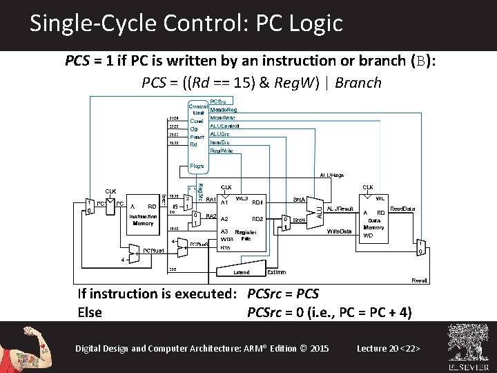
Single-Cycle Control: PC Logic PCS = 1 if PC is written by an instruction or branch (B): PCS = ((Rd == 15) & Reg. W) | Branch If instruction is executed: PCSrc = PCS Else PCSrc = 0 (i. e. , PC = PC + 4) Digital Design and Computer Architecture: ARM® Edition © 2015 Lecture 20 <22>
Single-Cycle Control Digital Design and Computer Architecture: ARM® Edition © 2015 Lecture 20 <23>
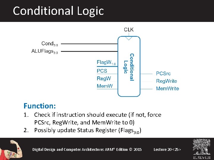
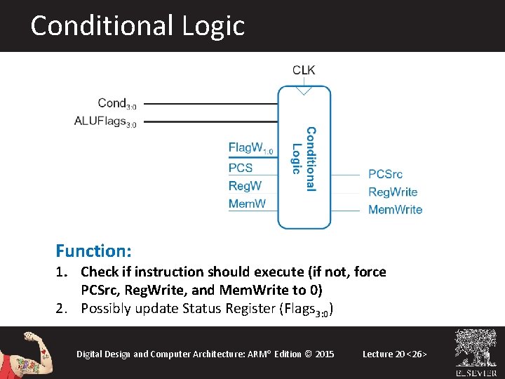
Single-Cycle Control: Cond. Logic Digital Design and Computer Architecture: ARM® Edition © 2015 Lecture 20 <24>
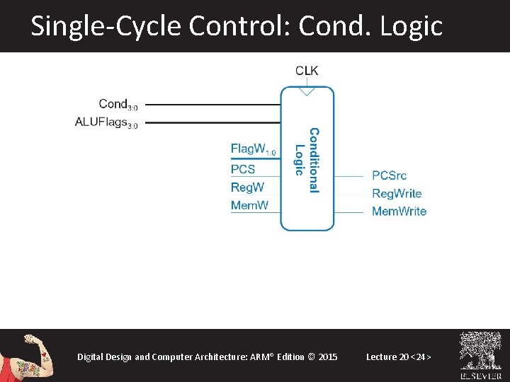
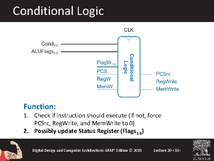
Conditional Logic Function: 1. Check if instruction should execute (if not, force PCSrc, Reg. Write, and Mem. Write to 0) 2. Possibly update Status Register (Flags 3: 0) Digital Design and Computer Architecture: ARM® Edition © 2015 Lecture 20 <25>
Conditional Logic Function: 1. Check if instruction should execute (if not, force PCSrc, Reg. Write, and Mem. Write to 0) 2. Possibly update Status Register (Flags 3: 0) Digital Design and Computer Architecture: ARM® Edition © 2015 Lecture 20 <26>
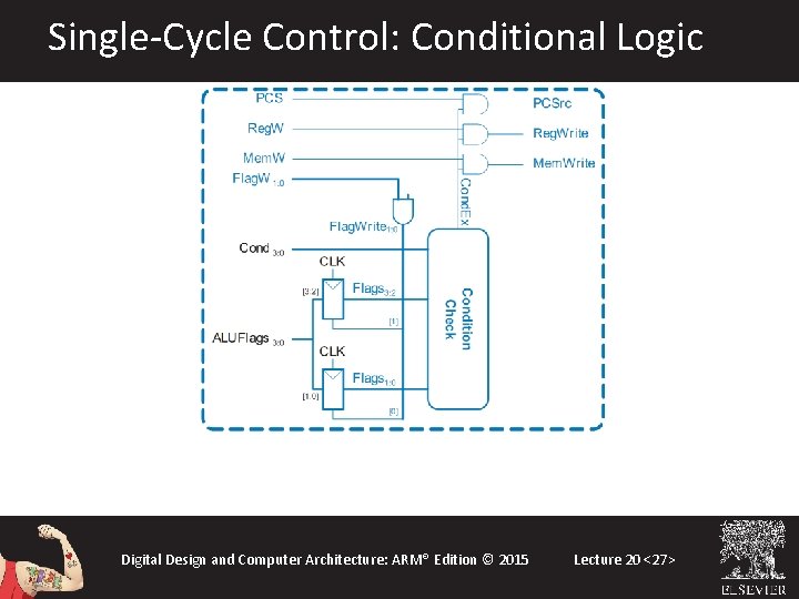
Single-Cycle Control: Conditional Logic Digital Design and Computer Architecture: ARM® Edition © 2015 Lecture 20 <27>
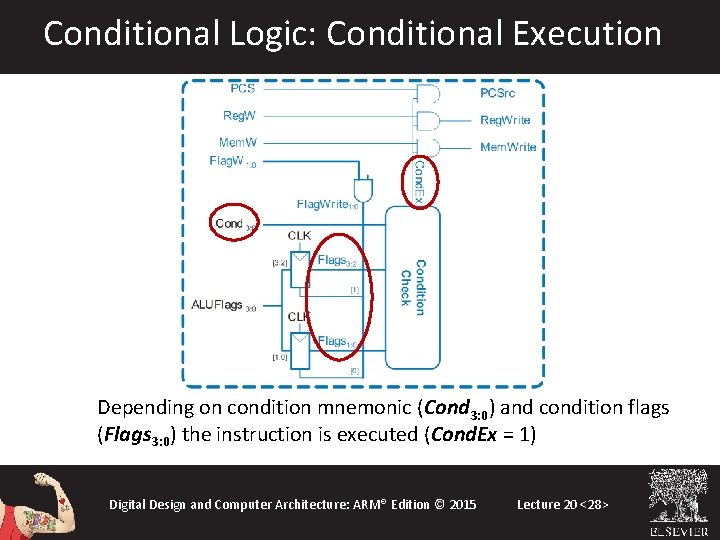
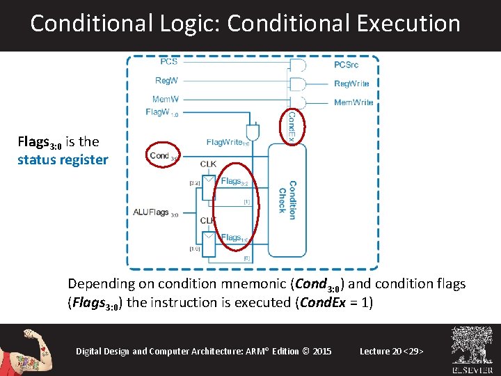
Conditional Logic: Conditional Execution Depending on condition mnemonic (Cond 3: 0) and condition flags (Flags 3: 0) the instruction is executed (Cond. Ex = 1) Digital Design and Computer Architecture: ARM® Edition © 2015 Lecture 20 <28>
Conditional Logic: Conditional Execution Flags 3: 0 is the status register Depending on condition mnemonic (Cond 3: 0) and condition flags (Flags 3: 0) the instruction is executed (Cond. Ex = 1) Digital Design and Computer Architecture: ARM® Edition © 2015 Lecture 20 <29>
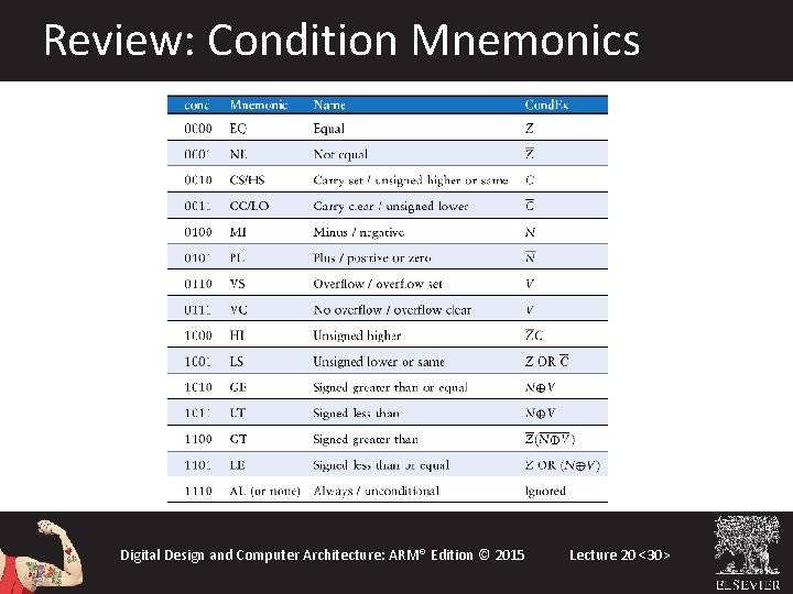
Review: Condition Mnemonics Digital Design and Computer Architecture: ARM® Edition © 2015 Lecture 20 <30>
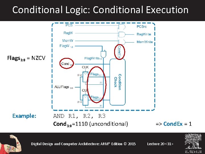
Conditional Logic: Conditional Execution Flags 3: 0 = NZCV Example: AND R 1, R 2, R 3 Cond 3: 0=1110 (unconditional) Digital Design and Computer Architecture: ARM® Edition © 2015 => Cond. Ex = 1 Lecture 20 <31>
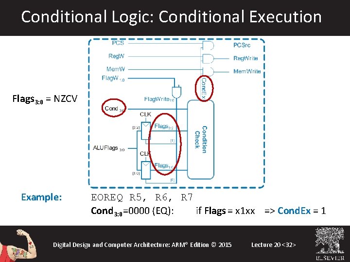
Conditional Logic: Conditional Execution Flags 3: 0 = NZCV Example: EOREQ R 5, R 6, R 7 Cond 3: 0=0000 (EQ): if Flags = x 1 xx => Cond. Ex = 1 Digital Design and Computer Architecture: ARM® Edition © 2015 Lecture 20 <32>
Conditional Logic Function: 1. Check if instruction should execute (if not, force PCSrc, Reg. Write, and Mem. Write to 0) 2. Possibly update Status Register (Flags 3: 0) Digital Design and Computer Architecture: ARM® Edition © 2015 Lecture 20 <33>
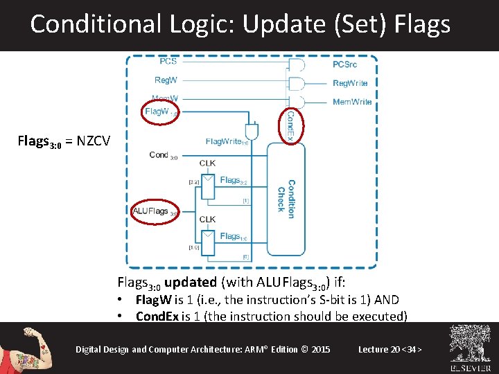
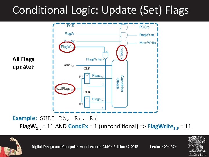
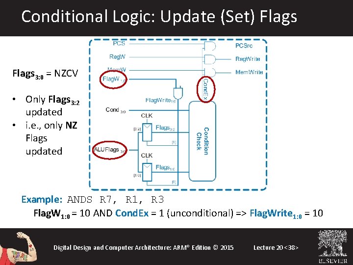
Conditional Logic: Update (Set) Flags 3: 0 = NZCV Flags 3: 0 updated (with ALUFlags 3: 0) if: • Flag. W is 1 (i. e. , the instruction’s S-bit is 1) AND • Cond. Ex is 1 (the instruction should be executed) Digital Design and Computer Architecture: ARM® Edition © 2015 Lecture 20 <34>
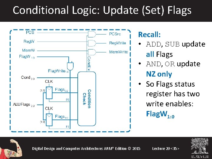
Conditional Logic: Update (Set) Flags Recall: • ADD, SUB update all Flags • AND, OR update NZ only • So Flags status register has two write enables: Flag. W 1: 0 Digital Design and Computer Architecture: ARM® Edition © 2015 Lecture 20 <35>
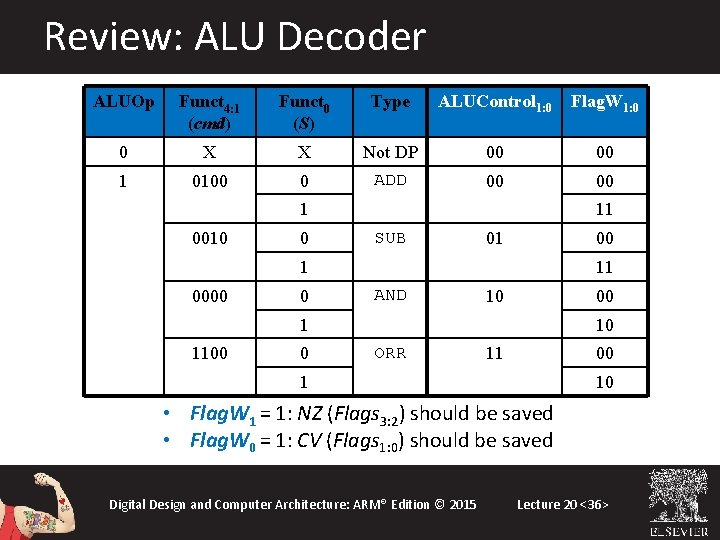
Review: ALU Decoder ALUOp Funct 4: 1 (cmd) Funct 0 (S) Type ALUControl 1: 0 Flag. W 1: 0 0 X X Not DP 00 00 1 0100 0 ADD 00 00 1 0010 0 11 SUB 01 0000 0 11 AND 10 00 1 1100 0 10 ORR 11 00 1 10 • Flag. W 1 = 1: NZ (Flags 3: 2) should be saved • Flag. W 0 = 1: CV (Flags 1: 0) should be saved Digital Design and Computer Architecture: ARM® Edition © 2015 Lecture 20 <36>
Conditional Logic: Update (Set) Flags All Flags updated Example: SUBS R 5, R 6, R 7 Flag. W 1: 0 = 11 AND Cond. Ex = 1 (unconditional) => Flag. Write 1: 0 = 11 Digital Design and Computer Architecture: ARM® Edition © 2015 Lecture 20 <37>
Conditional Logic: Update (Set) Flags 3: 0 = NZCV • Only Flags 3: 2 updated • i. e. , only NZ Flags updated Example: ANDS R 7, R 1, R 3 Flag. W 1: 0 = 10 AND Cond. Ex = 1 (unconditional) => Flag. Write 1: 0 = 10 Digital Design and Computer Architecture: ARM® Edition © 2015 Lecture 20 <38>
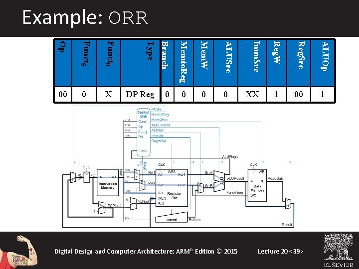
Example: ORR 0 0 Digital Design and Computer Architecture: ARM® Edition © 2015 XX ALUOp 0 Reg. Src ALUSrc 0 Reg. W Mem. W DP Reg Imm. Src Memto. Reg Funct 0 X Branch Funct 5 0 Type Op 00 1 Lecture 20 <39>
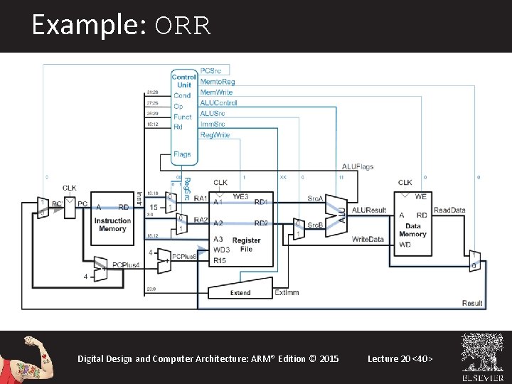
Example: ORR Digital Design and Computer Architecture: ARM® Edition © 2015 Lecture 20 <40>
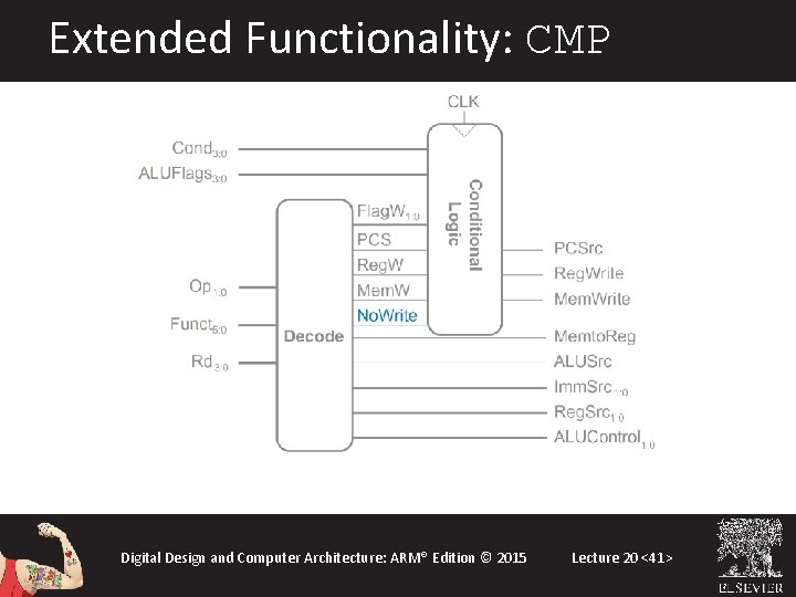
Extended Functionality: CMP Digital Design and Computer Architecture: ARM® Edition © 2015 Lecture 20 <41>
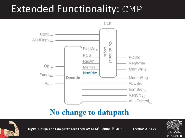
Extended Functionality: CMP No change to datapath Digital Design and Computer Architecture: ARM® Edition © 2015 Lecture 20 <42>
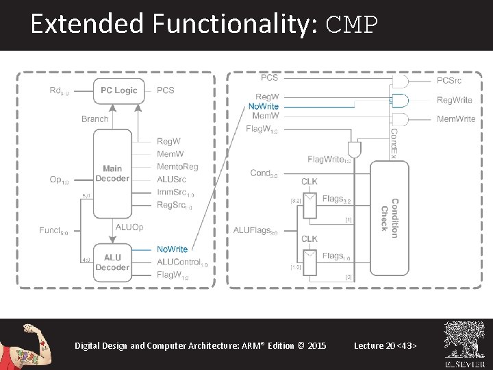
Extended Functionality: CMP Digital Design and Computer Architecture: ARM® Edition © 2015 Lecture 20 <43>
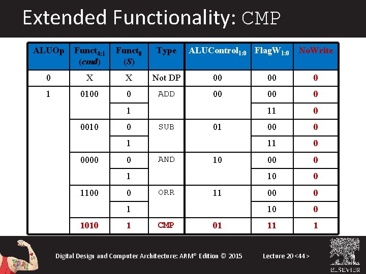
Extended Functionality: CMP ALUOp Funct 4: 1 (cmd) Funct 0 (S) Type ALUControl 1: 0 Flag. W 1: 0 0 X X Not DP 00 00 0 1 0100 0 ADD 00 00 0 11 0 00 0 10 0 11 1 1 0010 0 SUB 01 1 0000 0 AND 10 1 1100 0 ORR 11 1 1010 1 CMP 01 Digital Design and Computer Architecture: ARM® Edition © 2015 No. Write Lecture 20 <44>
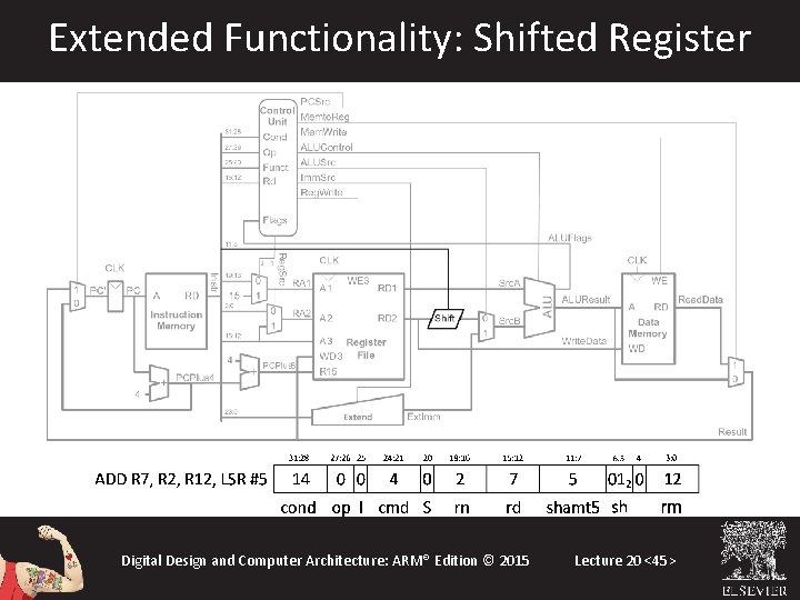
Extended Functionality: Shifted Register Digital Design and Computer Architecture: ARM® Edition © 2015 Lecture 20 <45>
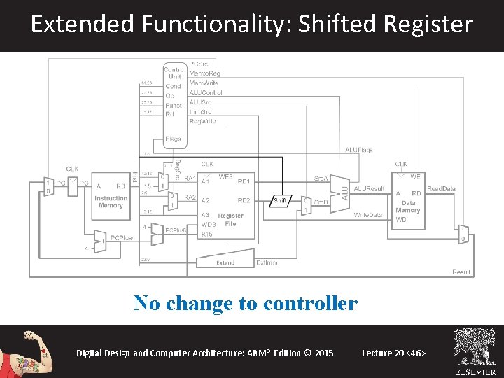
Extended Functionality: Shifted Register No change to controller Digital Design and Computer Architecture: ARM® Edition © 2015 Lecture 20 <46>
Review: Processor Performance Program Execution Time = (#instructions)(cycles/instruction)(seconds/cycle) = # instructions x CPI x TC Digital Design and Computer Architecture: ARM® Edition © 2015 Lecture 20 <47>
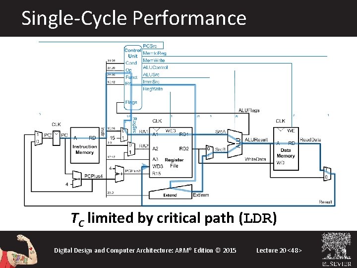
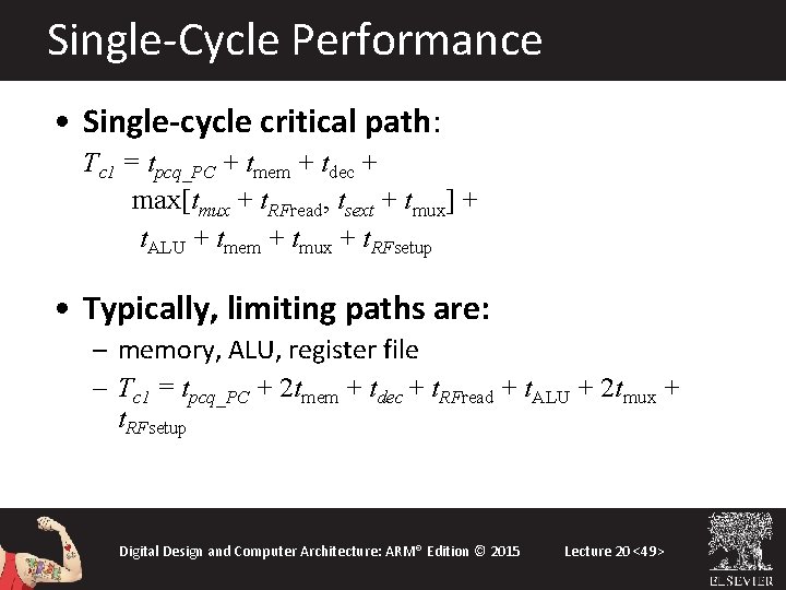
Single-Cycle Performance TC limited by critical path (LDR) Digital Design and Computer Architecture: ARM® Edition © 2015 Lecture 20 <48>
Single-Cycle Performance • Single-cycle critical path: Tc 1 = tpcq_PC + tmem + tdec + max[tmux + t. RFread, tsext + tmux] + t. ALU + tmem + tmux + t. RFsetup • Typically, limiting paths are: – memory, ALU, register file – Tc 1 = tpcq_PC + 2 tmem + tdec + t. RFread + t. ALU + 2 tmux + t. RFsetup Digital Design and Computer Architecture: ARM® Edition © 2015 Lecture 20 <49>
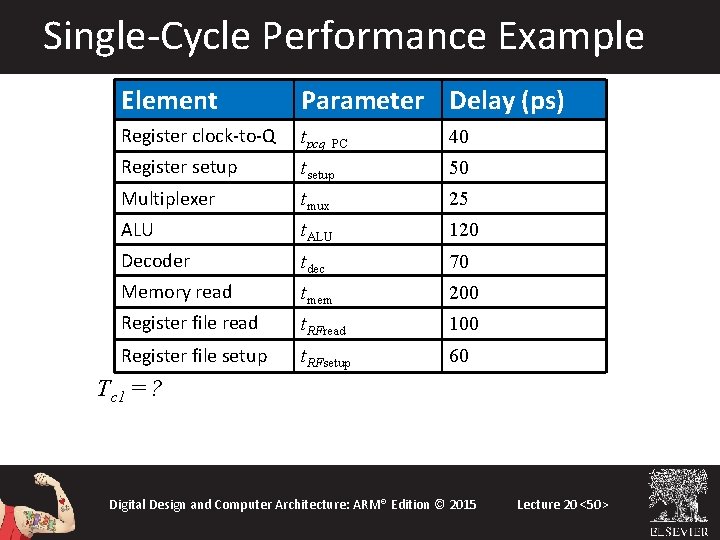
Single-Cycle Performance Example Element Parameter Delay (ps) Register clock-to-Q tpcq_PC 40 Register setup tsetup 50 Multiplexer tmux 25 ALU t. ALU 120 Decoder tdec 70 Memory read tmem 200 Register file read t. RFread 100 Register file setup t. RFsetup 60 Tc 1 = ? Digital Design and Computer Architecture: ARM® Edition © 2015 Lecture 20 <50>
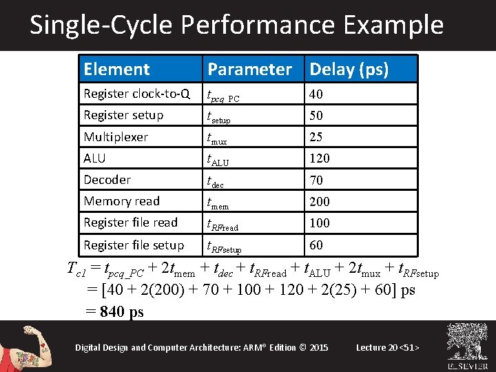
Single-Cycle Performance Example Element Parameter Delay (ps) Register clock-to-Q tpcq_PC 40 Register setup tsetup 50 Multiplexer tmux 25 ALU t. ALU 120 Decoder tdec 70 Memory read tmem 200 Register file read t. RFread 100 Register file setup t. RFsetup 60 Tc 1 = tpcq_PC + 2 tmem + tdec + t. RFread + t. ALU + 2 tmux + t. RFsetup = [40 + 2(200) + 70 + 100 + 120 + 2(25) + 60] ps = 840 ps Digital Design and Computer Architecture: ARM® Edition © 2015 Lecture 20 <51>
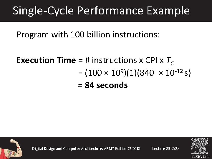
Single-Cycle Performance Example Program with 100 billion instructions: Execution Time = # instructions x CPI x TC = (100 × 109)(1)(840 × 10 -12 s) = 84 seconds Digital Design and Computer Architecture: ARM® Edition © 2015 Lecture 20 <52>