Design Codes Standards tolerances fits Codes Code A


 � � IT grade is a group of tolerances. Each")


- Slides: 28
Design Codes & Standards, tolerances, fits
Codes �Code: A code is a set of specifications for the analysis, design, manufacture and construction of something. The purpose of a code is to achieve a specified degree of safety, efficiency, and performance or quality.
What are standards? �Standards are an important part of our society, serving as rules to measure or judge capacity, quantity, content, extent, value and quality. Some standards take the form of an actual item such as the atomic clock which serves as the reference for measuring time throughout the world. Others set criteria for use and practice in industry and for products used in everyday life. This introduction, however, deals primarily with standards that set a level of adequacy for structures and machines. It is these standards, above all others, which must be addressed before any engineering design project can be started
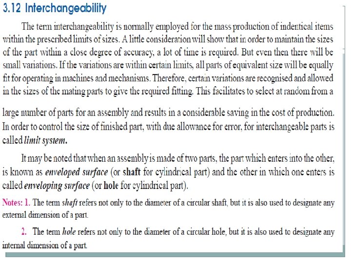
Important terms used in Limit system � 1. Nominal size. It has no specified limits or accuracy but indicates a close approximation to some standard size. For eg. a half inch nut will fit into a half inch bolt. � 2. Basic size: It is the exact theoretical size from which the limits are established through the applications of allowances and tolerances � 3. Actual size. � It is the actual measured dimension of the part. The difference between the basic size and the actual size should not exceed a certain limit, otherwise it will interfere with the inter changeability of the mating parts. � 4. Limits of sizes. There are two extreme permissible sizes for a dimension of the part as shown in Fig. 3. 1. The largest permissible size for a dimension of the part is called upper or high or maximum limit, whereas the smallest size of the part is known as lower or minimum limit.
� 5. Allowance. It is the difference between the basic dimensions of the mating parts. The �allowance may be positive or negative. When the shaft size is less than the hole size, then the allowance is positive and when the shaft size is greater than the hole size, then the allowance is negative.
� 6. Tolerance. � It is the difference between the upper limit and lower limit of a dimension. In other words, it is the maximum permissible variation in a dimension. The tolerance may be unilateral or bilateral. When all the tolerance is allowed on one side of the nominal size, e. g. 0. 000 20– 0. 004 + , then it is said to be unilateral system of tolerance. The unilateral system is mostly used in industries as it permits changing the tolerance value while still retaining the same allowance or type of fit. bilateral system of tolerance. In this case + 0. 002 is the upper limit and – 0. 002 is the lower limit. � The method of assigning unilateral and bilateral tolerance is shown in Fig. 3. 2 (a) and � (b) respectively.
� 7. Tolerance zone. It is the zone between the maximum and minimum limit size, as shown in � Fig. 3. 3.
. Zero line. It is a straight line corresponding to the basic size. The � 8 deviations are measured from this line. The positive and negative deviations are shown above and below the zero line respectively. � 9. Upper deviation. It is the algebraic difference between the maximum size and the basic size. The upper deviation of a hole is represented by a symbol ES (Ecart Superior) and of a shaft, it is represented by es. � 10. Lower deviation. It is the algebraic difference between the minimum size and the basic size. The lower deviation of a hole is represented by a symbol EI (Ecart Inferior) and of a shaft, it is represented by ei. � 11. Actual deviation. It is the algebraic difference between an actual size and the corresponding basic size. � 12. Mean deviation. It is the arithmetical mean between the upper and lower deviations.
� 13. Fundamental deviation. The fundamental deviation is the closest deviation to the basic size. The fundamental deviation is the smaller of the UD and the LD
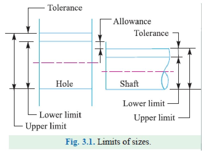
FITS � The degree of tightness or looseness between the two mating parts is known as a fit of the parts. The nature of fit is characterised by the presence and size of clearance and interference. The clearance is the amount by which the actual size of the shaft is less than the actual size of the mating hole in an assembly as shown in Fig. 3. 5 (a). In other words, the clearance is the difference between the sizes of the hole and the shaft before assembly. The difference must be positive. The interference is the amount by which the actual size of a shaft is larger than the actual finished size of the mating hole in an assembly as shown in Fig. 3. 5 (b). In other words, the interference is the arithmetical difference between the sizes of the hole and the shaft, before assembly. The difference must be negative.
� 1. Clearance fit. In this type of fit, the size limits for mating parts are so selected that clearance between them always occur, as shown in Fig. 3. 5 (a). It may be noted that in a clearance fit, the tolerance zone of the hole is entirely above the tolerance zone of the shaft. �In a clearance fit, the difference between the minimum size of the hole and the maximum size of the shaft is known as minimum clearance whereas the difference between the maximum size of the hole and minimum size of the shaft is called maximum clearance as shown in Fig. 3. 5 (a).
� 2. Interference fit. In this type of fit, the size limits for the mating parts are so selected that interference between them always occur, as shown in Fig. 3. 5 (b). It may be noted that in an interference fit, the tolerance zone of the hole is entirely below the tolerance zone of the shaft. In an interference fit, the difference between the maximum size of the hole and the minimum size of the shaft is known as minimum interference, whereas the difference between the minimum size of the hole and the maximum size of the shaft is called maximum interference, as shown in Fig. 3. 5 (b). �The interference fits may be shrink fit, heavy drive fit and light drive fit.
� 3. Transition fit. In this type of fit, the size limits for the mating parts are so selected that either a clearance or interference may occur depending upon the actual size of the mating parts, as shown in Fig. 3. 5 (c). It may be noted that in a transition fit, the tolerance zones of hole and shaft overlap. The transition fits may be force fit, tight fit and push fit. �Transition fits are a compromises between clearance and interference fits. They are used for applications where accurate location is important but either a small amount of clearance or interference is permissible. As shown in Figure 3. 3, there is overlapping of tolerance zones of the hole and shaft.
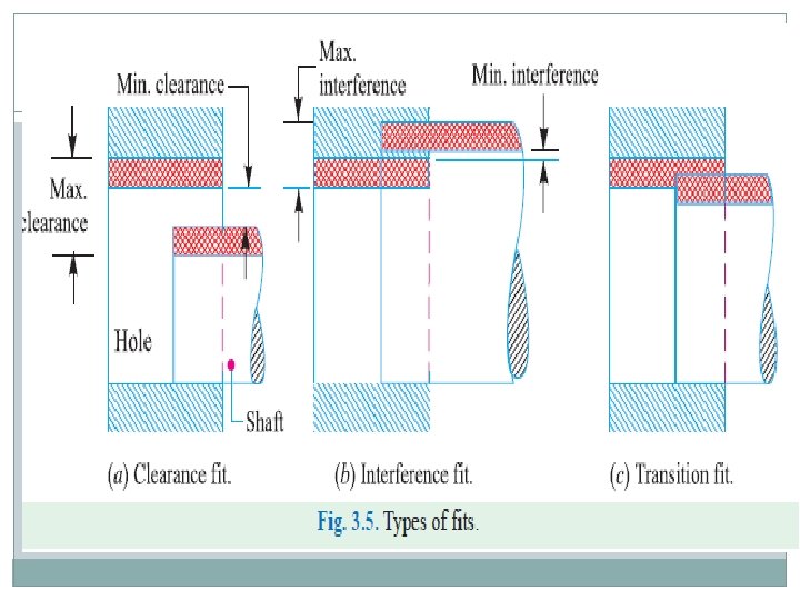
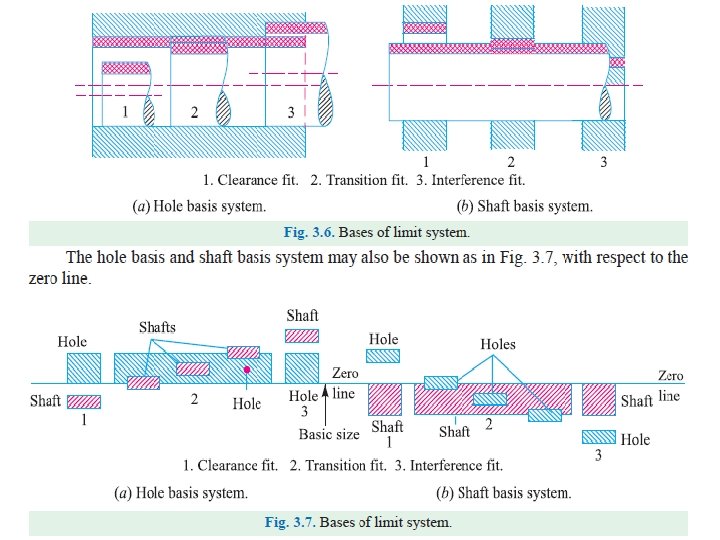
Basis Of Limit system � 1. Hole basis system. When the hole is kept as a constant member (i. e. when the lower deviation �of the hole is zero) and different fits are obtained by varying the shaft size, as shown in Fig. 3. 6 (a), �then the limit system is said to be on a hole basis. � 2. Shaft basis system. When the shaft is kept as a constant member (i. e. when the upper deviation �of the shaft is zero) and different fits are obtained by varying the hole size, as shown in Fig. 3. 6 (b), �then the limit system is said to be on a shaft basis.
International Tolerance Grade (IT) � � IT grade is a group of tolerances. Each of the tolerances of this system is marked "IT" with attached grade of accuracy (IT 01, IT 0, IT 1. . . IT 18). IT Grades reference ISO 286. The magnitude of the tolerance zone is the variation in part size. IT groups of tolerances such that tolerances for a particular IT number have the same relative level of accuracy but vary depending on the basic size. A smaller grate of IT number provides a smaller tolerance zone. The fundamental IT deviation for hole basis is designated by "H", the shaft designated by "h". Tolerance Symboles: � The tolerance symbol is established by combining the IT grade number and position letter for tolerance. Capital letter like "H" for hole, and lower case letter like "h" for shaft.
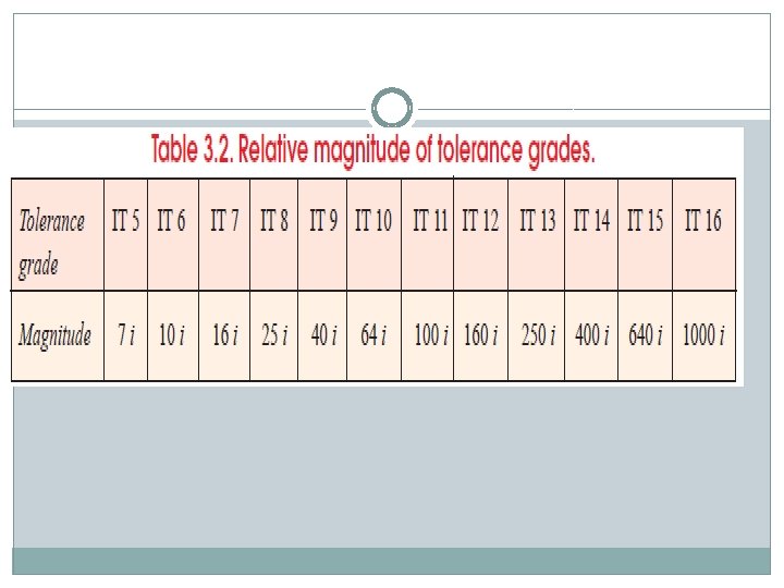
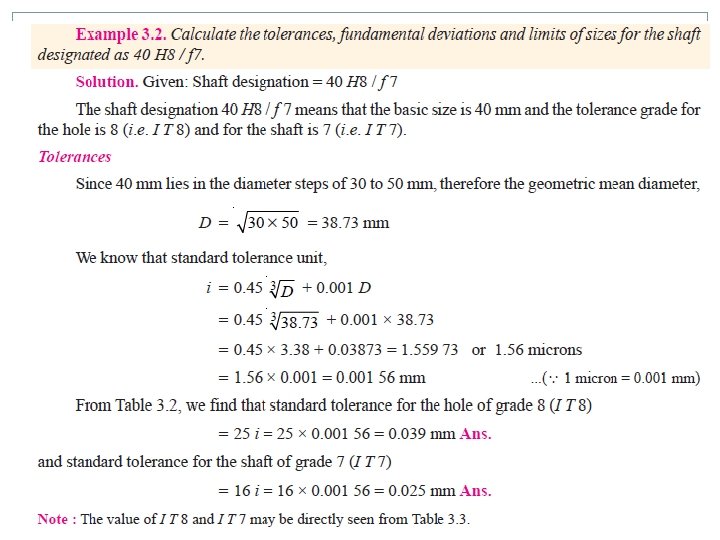
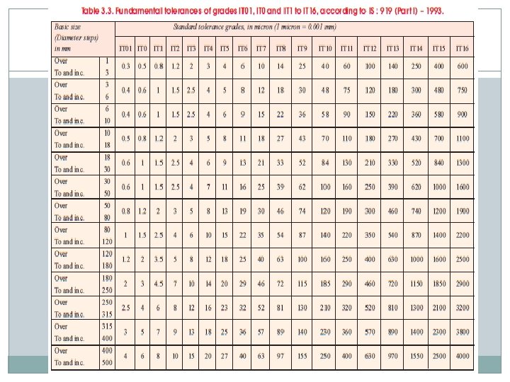
Indian Standard System of Limits and Fits � According to Indian standard [IS : 919 (Part I)-1993], the system of limits and fits comprises 18 grades of fundamental tolerances i. e. grades of accuracy of manufacture and 25 types of fundamental deviations indicated by letter symbols for both holes and shafts (capital letter A to ZC for holes and small letters a to z c for shafts) in diameter steps ranging from 1 to 500 mm. A unilateral hole basis system is recommended but if necessary a unilateral or bilateral shaft basis system may also be used. The 18 tolerance grades are designated as IT 01, IT 0 and IT 1 to IT 16. These are called standard � tolerances. � The standard tolerances for grades IT 5 to IT 7 are determined in terms of standard tolerance unit (i) in microns, where i (microns) = 0. 45 3 D + 0. 001 D, where D is the size or geometric mean diameter in mm. � The following table shows the relative magnitude for grades between IT 5 and IT 16.
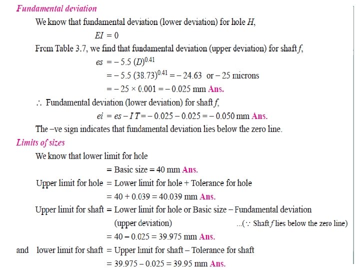
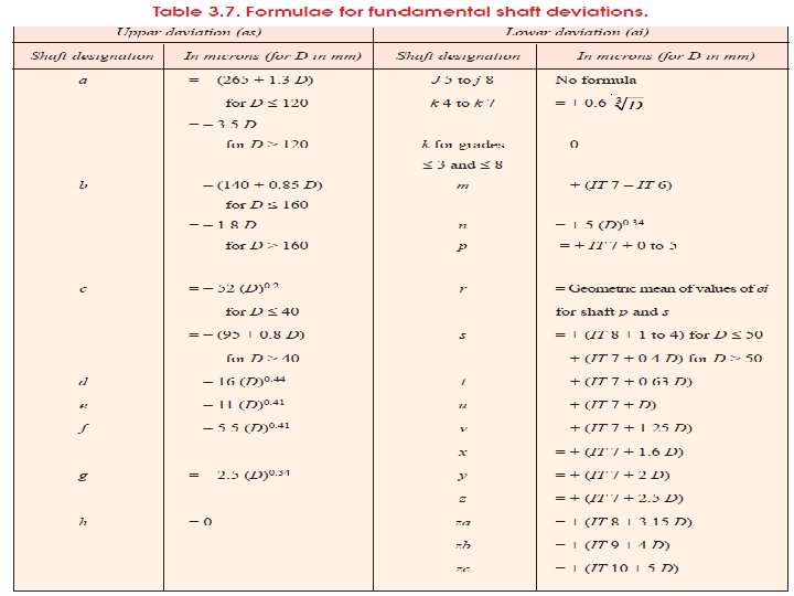
Shafts � We have already discussed that for holes, the upper deviation is denoted by ES and the lower deviation by EI. � Similarly for shafts, the upper deviation is represented by es and the lower deviation by ei. According to Indian standards, for each letter symbol, the magnitude and sign for one of the � two deviations (i. e. either upper or lower deviation), which is � known as fundamental deviation, have been determined by � means of formulae given in Table 3. 7. The other deviation may be calculated by using the absolute value of the standard tolerance (IT) from the following relation: � ei = es – IT or es = ei + IT � It may be noted for shafts a to h, the upper deviations (es) are considered whereas for shafts j to Zc, the lower deviation (ei) is to be considered.
The selection of letter freezes one limit of hole / shaft (how much away from Basic size) Representation of Tolerance 1) Letter Symbol Basic Size 45 E 8/e 7 One can have different possible combinations; eg. 45 H 6 g 7, 45 H 8 r 6, 45 E 5 p 7 E. S. – upper deviation E. I. – lower deviation H : lower deviation of hole is zero h : upper deviation of shaft is zero