Counters Discussion D 8 3 Counters Divideby8 Counter

Counters Discussion D 8. 3

Counters • Divide-by-8 Counter • Behavioral Counter in Verilog • Counter using One-Hot State Machine

Divide-by-8 Counter A state diagram for a divide by 8 counter

Divide-by-8 Counter Present state State Q 2 Q 1 Q 0 s 1 s 2 s 3 s 4 s 5 s 6 s 7 0 0 1 1 0 1 0 1 Next state D 2 D 1 D 0 0 1 1 0 A state-transition table 1 0 1 0

Divide-by-8 Counter Present state State Q 2 Q 1 Q 0 s 1 s 2 s 3 s 4 s 5 s 6 s 7 0 0 1 1 0 1 0 1 Next state D 2 D 1 D 0 0 1 1 0 1 0 1 0 D 0 Q 0 D 1 Q 1 D 2 Q 2

Divide-by-8 Counter Present state State Q 2 Q 1 Q 0 s 1 s 2 s 3 s 4 s 5 s 6 s 7 0 0 1 1 0 1 0 1 Next state D 2 D 1 D 0 0 1 1 0 1 0 1 0 Q 1 Q 0 00 Q 2 01 10 1 11 1 D 2 = ~Q 2 & Q 1 & Q 0 | Q 2 & ~Q 1 | Q 2 & ~Q 0

Divide-by-8 Counter Present state State Q 2 Q 1 Q 0 s 1 s 2 s 3 s 4 s 5 s 6 s 7 0 0 1 1 0 1 0 1 Next state D 2 D 1 D 0 0 1 1 0 1 0 1 0 Q 1 Q 0 00 Q 2 01 11 10 0 1 1 1 D 1 = ~Q 1 & Q 0 | Q 1 & ~Q 0

Divide-by-8 Counter Present state State Q 2 Q 1 Q 0 s 1 s 2 s 3 s 4 s 5 s 6 s 7 0 0 1 1 0 1 0 1 Next state D 2 D 1 D 0 0 1 1 0 1 0 1 0 Q 1 Q 0 00 Q 2 01 11 10 0 1 1 1 D 0 = ~Q 0

Divide-by-8 Counter A Divide by 8 counter Circuit using D Flip-flops
; input clk ; wire clk ; input clr")
module DFF (D, clk, clr, Q); input clk ; wire clk ; input clr ; wire clr ; input D ; wire D ; output Q ; reg Q ; always @(posedge clk or posedge clr) if(clr == 1) Q <= 0; else Q <= D; endmodule
; input clr ; wire")
module count 3 ( Q , clr , clk ); input clr ; wire clr ; input clk ; wire clk ; output [2: 0] Q ; wire [2: 0] D ; assign D[2] = ~Q[2] & Q[1] & Q[0] | Q[2] & ~Q[1] | Q[2] & ~Q[0]; assign D[1] = ~Q[1] & Q[0] | Q[1] & ~Q[0]; D 0 Q 0 D 1 Q 1 D 2 Q 2 assign D[0] = ~Q[0]; DFF U 2(. D(D[2]), . clk(clk), . clr(clr), . Q(Q[2])); DFF U 1(. D(D[1]), . clk(clk), . clr(clr), . Q(Q[1])); DFF U 0(. D(D[0]), . clk(clk), . clr(clr), . Q(Q[0])); endmodule

count 3 Simulation

Counters • Divide-by-8 Counter • Behavioral Counter in Verilog • Counter using One-Hot State Machine
 Behavior always @(posedge clk or")
3 -Bit Counter clk count 3 Q(2 downto 0) Behavior always @(posedge clk or posedge clr) begin if(clr == 1) Q <= 0; else Q <= Q + 1; end
; counter 3. v input clr ; wire")
module counter 3 (clk, clr, Q ); counter 3. v input clr ; wire clr ; input clk ; wire clk ; output [2: 0] Q ; reg [2: 0] Q ; // 3 -bit counter always @(posedge clk or posedge clr) begin Asynchronous clear if(clr == 1) Q <= 0; else Q <= Q + 1; end Output count increments endmodule on rising edge of clk

counter 3 Simulation

Recall Divide-by-8 Counter Present state State Q 2 Q 1 Q 0 s 1 s 2 s 3 s 4 s 5 s 6 s 7 0 0 1 1 0 1 0 1 Next state D 2 D 1 D 0 0 1 1 0 1 0 1 0 D 0 Q 0 D 1 Q 1 D 2 Q 2 Use Q 2, Q 1, Q 0 as inputs to a combinational circuit to produce an arbitrary waveform.

Example State Q 2 Q 1 s 0 s 1 s 2 s 3 s 4 s 5 s 6 s 7 0 0 1 1 1 0 0 1 1 0 Q 0 D 2 D 1 D 0 y 0 1 0 1 0 0 0 1 1 0 1 0 1 0 1 1 0 0 0 1 0 1 1 1 Q 0 00 Q 2 0 01 1 11 10 1 1 y = ~Q 2 & ~Q 1 | Q 2 & Q 0 0 1 0 1

Counters • Divide-by-8 Counter • Behavioral Counter in Verilog • Counter using One-Hot State Machine
 to implement")
One-Hot State Machines Instead of using the minimum number of flip-flops (3) to implement the state machine, one-hot encoding uses one flip-flop per state (8) to implement the state machine. D 0 Q 0 D 1 Q 1 D 2 Q 2
")
Why use One-Hot State Machines? Using one-hot encoding or one flip-flop per state (8) will normally simplify the combinational logic at the expense of more flip-flops. Let's see how for the 3 -bit counter

One-Hot Encoding Present state State Q 2 Q 1 Q 0 s 1 s 2 s 3 s 4 s 5 s 6 s 7 0 0 1 1 0 1 0 1 Next state D[0: 7] s 1 s 2 s 3 s 4 s 5 s 6 s 7 s 0 Think of each state as a flip-flop D[i] = s[i-1] This is just a ring counter!

3 -bit Counter State Q 2 Q 1 s 0 s 1 s 2 s 3 s 4 s 5 s 6 s 7 0 0 1 1 Q 0 0 1 0 1 Q 2 = s 4 | s 5 | s 6 | s 7 Q 1 = s 2 | s 3 | s 6 | s 7 Q 0 = s 1 | s 3 | s 5 | s 7
![module cnt 3 hot 1(clk, clr, Q); input clk; input clr; output [2: 0]](http://slidetodoc.com/presentation_image/fe24aa6f48fdd5948f692cf0130cbfe2/image-24.jpg "module cnt 3 hot 1(clk, clr, Q); input clk; input clr; output [2: 0]")
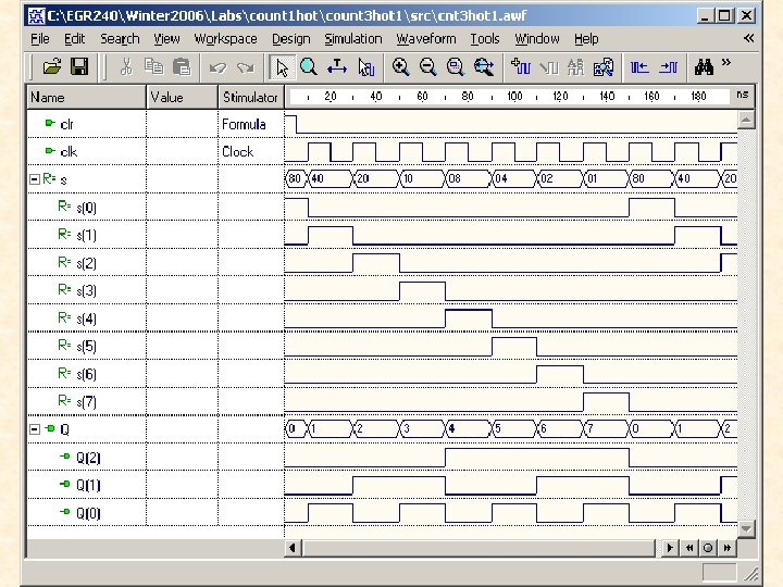
module cnt 3 hot 1(clk, clr, Q); input clk; input clr; output [2: 0] Q; wire [2: 0] Q; reg [0: 7] s; // 8 -bit Ring Counter always @(posedge clk or posedge clr) begin if(clr == 1) s <= 8'b 10000000; else begin s[0] <= s[7]; s[1: 7] <= s[0: 6]; end // assign 3 -bit counter Q[2] = s[4] | s[5] | s[6] | s[7]; Q[1] = s[2] | s[3] | s[6] | s[7]; Q[0] = s[1] | s[3] | s[5] | s[7]; endmodule
- Slides: 25