UPDOWN SYNCHRONOUS COUNTERS An updown counter is one


- Slides: 7
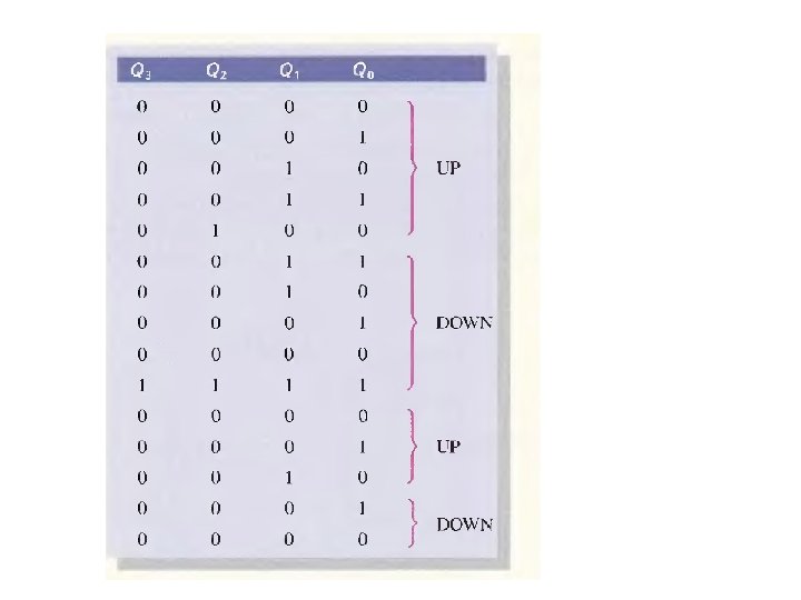
UP/DOWN SYNCHRONOUS COUNTERS An up/down counter is one that is capable of progressing in either direction through a certain sequence. An up/down counter, sometimes called a bidirectional counter, can have any specified sequence of states. A 3 -bit binary counter that advances upward through its sequence (0, I, 2, 3, 4, 5, 6, 7) and then can be reversed so that it goes through the sequence in the opposite direction (7, 6, 5, 4, 3, 2, 1, 0) is an illustration of up/down sequential operation. In general, most up/down counters can be reversed at any point in their sequence. For instance, the 3 -bit binary counter can be made to go through the following sequence: Table below shows the complete up/down sequence for a 3 -bit binary counter. The arrows indicate the state-to-state movement of the counter for both its UP and its DOWN modes of operation. An examination of Qo for both the up and down sequences shows that FFO toggles on each clock pulse. Thus, the J 0 and Ko inputs of FFO are
For the up sequence, Q 1 changes state on the next clock pulse when Qo = 1. For the down sequence, Q 1 changes on the next clock pulse when Qo = O. Thus, the J 1 and K 1 inputs of FF 1 must equal I under the conditions expressed by the following equation: Up/Down sequence for a 3 -bit binary counter.
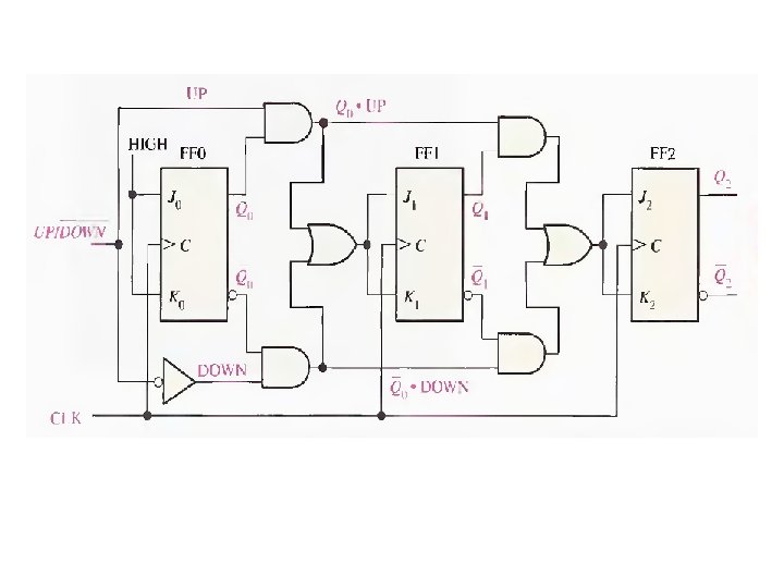
For the up sequence, Q 2 changes state on the next clock pulse when Qo = QJ = I. For the down sequence, Q 2 changes on the next clock pulse when Qo = Q 1 = O. Thus, the j 2 and K 2 inputs of FF 2 must equal I under the conditions expressed by the following equation: Each of the conditions for the J and K inputs of each flip-flop produces a toggle at the appropriate point in the counter sequence. Figure below shows a basic implementation of a 3 -bit up/down binary counter using the logic equations just developed for the 1 and K inputs of each flip-flop Notice that the UP/ DOWN control input is HIGH for UP and LOW for DOWN.
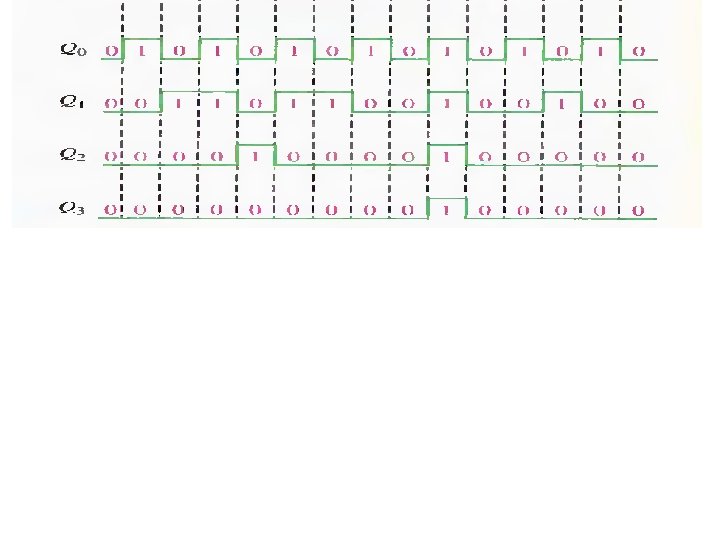
Example: show the timing diagram and determine the sequence of a 4 -bit synchronous binary up/down counter if the clock and UP/DOWN control inputs have waveforms as shown in figure. The counter starts in the all Os state and is positive edge-triggered. Solution: the timing diagram showing the Q outputs is shown in figure.