CHAPTER 8 IDEAL OPERATIONAL AMPLIFIER AND OPAMP CIRCUITS


 = voltage")
 = -(150/12) =")

 = voltage at node 2")


- Slides: 23
CHAPTER 8 IDEAL OPERATIONAL AMPLIFIER AND OP-AMP CIRCUITS
inverting output non-inverting Op-amp circuit symbol • Open loop mode • Vo = Aod ( v 2 – v 1) – Aod is referred to as the open loop gain. – Notice that is v 2 = v 1, the open loop gain equals to
Final Exam SEM II 2012/2013 An ideal op-amp, was measured in a lab experiment in open-loop mode. Determine the open loop gain (Aod) and complete the table below which shows the results of the experiment. V 1 (1) -1 m. V -0. 5 V 0. 99 V V 2 (2) +1 m. V V -0. 506 1 V Vo (3) 1 V -3 V 5 V
• Op amp can be configured to be used for different type of circuit applications: – Inverting Amplifier – Non – inverting Amplifier – Summing Amplifier – Integrator – Differentiator
• Two main characteristics: • We want the open loop gain to be equal to which means that v 2 = v 1 0 0 • We also want the input resistance to be equal to , hence there is no current going into the op-amp
Inverting Amplifier Op-amp as an inverting amplifier Voltage at node 1 (inverting) = voltage at node 2 (non-inverting ) KCL at node 1: (Vi – 0) / R 1 = (0 – Vo) / R 2 Vi / R 1 = - Vo / R 2 Vo = - R 2 Vi R 1
Exercise 8. 3 Gain = - (R 2 / R 1) = -(150/12) = -12. 5
Can the voltage gain be calculated using the same formula? Try and use the same method in deriving Vo/Vi
Non - Inverting Amplifier Voltage at node 1 (inverting) = voltage at node 2 (non-inverting ) KCL at node 1: (0– Vi) / R 1 = (Vi – Vo) / R 2 -(Vi / R 1) = (Vi / R 2) – (Vo / R 2) Vo / R 2 = (Vi / R 2) + (Vi / R 1) = Vi 1 + 1 R 2 Vo / Vi = R 2 1 + 1 R 2 R 1 Noninverting amplifier
Voltage Follower / Buffer Amplifier Vo = Vi Hence, gain = 1
Summing Amplifier Similarly, i 1 + i 2 + i 3 – i 4 – 0 = 0 Example 8. 2 Design a summing amplifier as shown in figure to produce a specific output signal, such that vo = 1. 25 – 2. 5 cos t volt. Assume the input signals are v. I 1 = -1. 0 V, v. I 2 = 0. 5 cos t volt. Assume the feedback resistance RF = 10 k
Solution: output voltage
Other Op-Amp Applications
Integrator Integrator circuit
Differentiator EXAMPLE 8. 4 Differentiator circuit
Calculating Gain and Design Questions NON - INVERTING Calculating Output and Design Questions SUMMING AMPLIFIER DIFFERENTIATOR AMPLIFIER INTEGRATOR AMPLIFIER
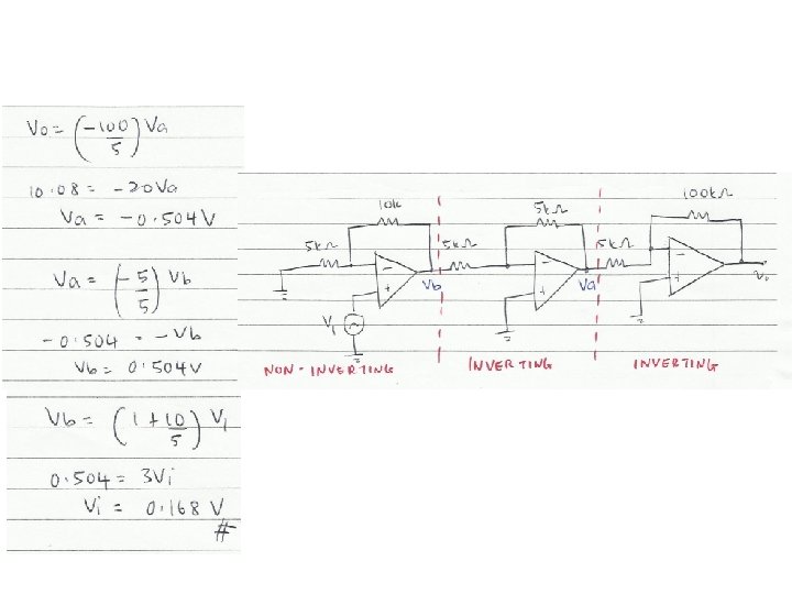
Calculate the input voltage if the final output, VO is 10. 08 V.
What is the value of Vin 1 from the figure above?
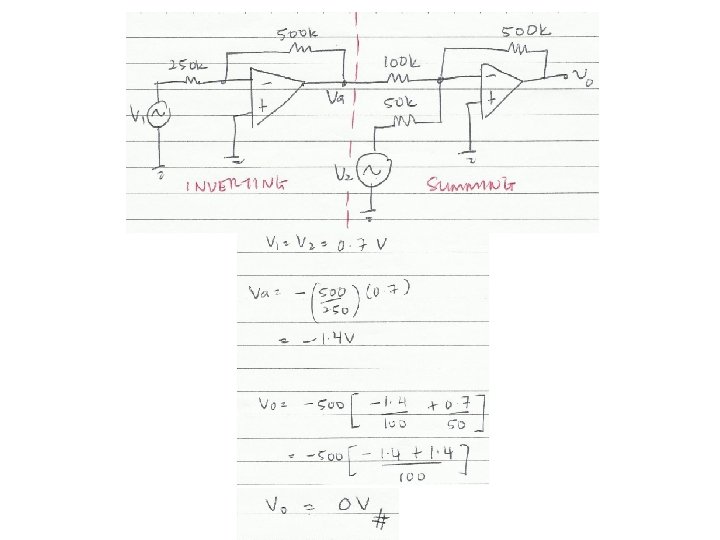
Calculate the output voltage, VO if V 1 = V 2 = 700 m. V
IDQ
Answering the questions • There are 5 questions. Answer all. • Chapter 1 & 2 will not be in the final exam • Organize your thoughts. When it is organized, so will your workflow. – Messy work will make the lecturers feel annoyed as they have to look for your answers – bear in mind that lecturer handling one section = 50 -60 students – each paper has 5 questions – TOTAL – 250 to 300 questions to mark • Don’t leave a question blank – just write down anything you know that might be related • Study smart, pray and tawakal.