Chap 5 The Operational Amplifier Contents 5 1

。 Input Current")
 Calculate vo if va =")


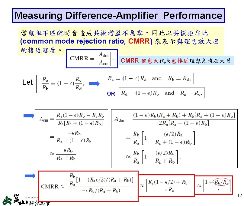
 和共模(common mode) 電壓輸入。 vo in terms of")


- Slides: 15
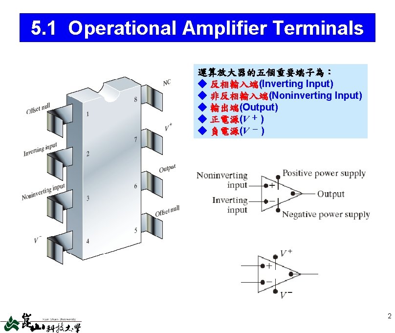
Chap. 5 The Operational Amplifier Contents 5. 1 5. 2 5. 3 5. 4 5. 5 5. 6 5. 7 Operational Amplifier Terminals Terminal Voltages and Currents The Inverting-Amplifier Circuit The Summing-Amplifier Circuit The Noninverting-Amplifier Circuit The Difference-Amplifier Circuit A More Realistic Model for the OP Amplifier Objectives 1. 能指明和描述運算放大器的五個端子,並應用電壓和 2. 電流的限制予以簡化,導出一理想運算放大器。 2. 能分析包含理想放大器的簡單電路,並分辨下列運算 放大器電路:反相放大器、和值放大器、非反相放大器 與差值放大器。 3. 了解比較實際的運算放大器模型,並能利用它來分析包 含這些放大器的簡單電路。 1
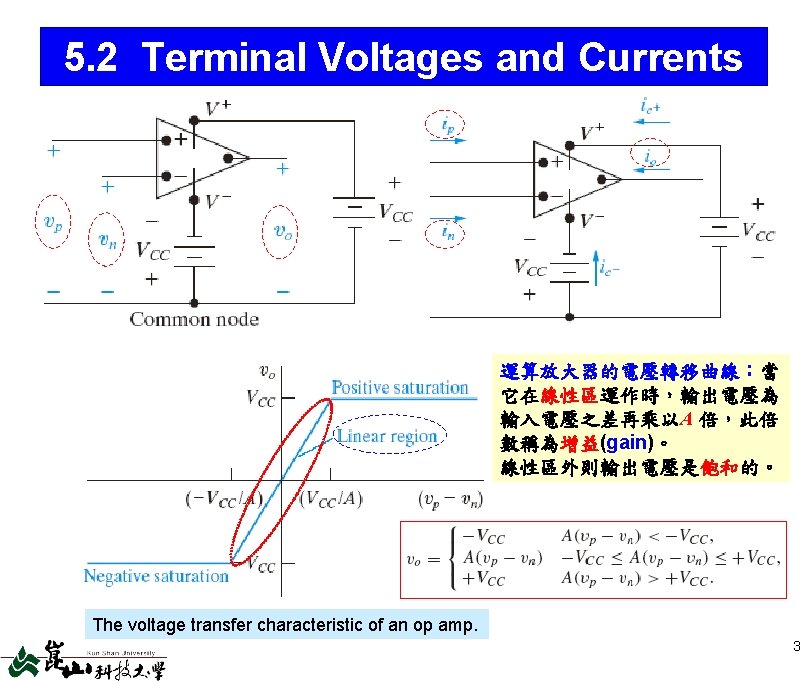
Input Voltage Constraint For Ideal Op Amp 理想運算放大器的輸入電壓限制條件: 在線性區時,因增益無限大,所以vp = vn,亦稱為虛短路(virtual short)。 Input Current Constraint For Ideal Op Amp 理想運算放大器的輸入電流限制條件: 因等效輸入電阻無限大,所以ip = in = 0。 From KCL, Symbol without the power supply terminals. 4
EX 5. 1 Analyzing an Op Amp Circuit a) Calculate vo if va = 1 V and vb = 0 V. b) Repeat (a) for va = 1 V and vb = 2 V. c) If va = 1. 5 V, specify the range of vb that avoids amplifier saturation. Ideal Negative feedback linear region No negative feedback saturation Then analyze and check! a) Because vo lies between ± VCC, the op amp is in its linear region. b) c) 5
5. 3 The Inverting-Amplifier Circuit Ideal Note: 6
Open-Loop Operation of an Inverting Amp Open-Loop Gain of the Op Amp Ideal Note: The op amp can operate open loop in the linear mode only if Also note that : 7
5. 4 The Summing-Amplifier Circuit Ideal @inverting input terminal: & 8
5. 5 The Noninverting-Amplifier Circuit Ideal & & 9
5. 6 The Difference-Amplifier Circuit Ideal @inverting input terminal: If 簡化的差值放大器 輸入電壓與輸出電壓關係 10
The Difference Amplifier-Another Perspective 重新定義輸入電壓: 差模(differential mode) 和共模(common mode) 電壓輸入。 vo in terms of vcm & vdm If 只放大輸入電壓的差模部分, 而消除共模部分。 11
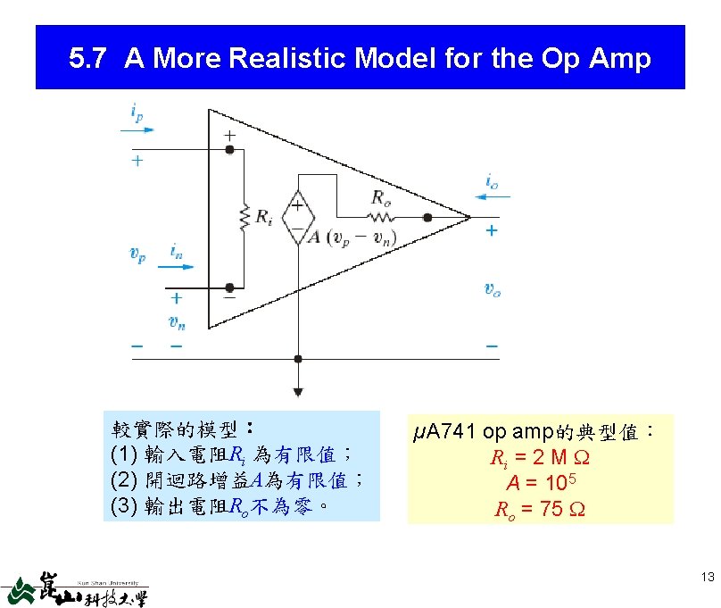
Analysis of an Inverting-Amplifier Circuit Using the More Realistic Op Amp Model 14
Analysis of a Noninverting-Amplifier Circuit Using the More Realistic Op Amp Model where What if Ro 0, A , and Ri ? 15