Operational Amp Pengertian Penguat operasional bahasa Inggris operational

Operational Amp
 atau yang biasa disebut op-amp")
Pengertian • • Penguat operasional (bahasa Inggris: operational amplifier) atau yang biasa disebut op-amp merupakan suatu komponen elektronika berupa integrated circuit (IC). Mempunyai penguatan yang sangat tinggi sehingga, bagian output Op-amp ini biasanya dikendalikan dengan umpan balik negatif (negative feedback).
, Inverting Amplifier, •")
Fungsi dari Op-amp : • Amplifier atau penguat biasa (non-Inverting Amplifier), Inverting Amplifier, • Komputer analog (operasi jumlah, kurang, integrasi, dan diferensiasi), • Pengubah tegangan, osilator, filter dll.

Simbol Op Amp
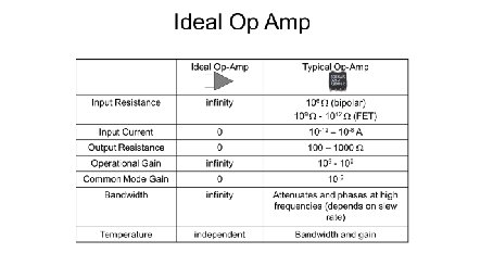
 ∞ 2.")
Karakteristik Parameter Ideal LM 741 LF 347 LM 318 Open-loop Gain (AOL) ∞ 2. 105 Input Resistance (Rin) ∞Ω 2 MΩ 1012 Ω 3 MΩ Output Resistance (Ro) 0Ω 75 Ω Gain Bandwidth Product ∞ Hz 1 MHz 4 MHz 15 MHz CMRR ∞ 90 d. B 100 d. B common-mode rejection ratio (CMRR) adalah kecenderungan dari perangkat untuk menolak input sinyal sama untuk kedua lead masukan

Op-Amp 741 VCC Q 8 Q 12 Q 13 Q 14 Q 9 Q 15 R 6 Symbol Q 2 Q 1 R 7 Q 19 R 5 CC Q 3 Q 18 OUT R 10 Q 4 VCC Q 21 −V E E Q 20 Q 23 Q 7 Q 16 Q 10 Q 5 Q 6 Q 17 R 9 Q 11 R 4 R 8 R 1 R 3 R 2 Q 24 −V E E offset adjust M. B. Patil, IIT Bombay

Op-amp: equivalent circuit OUT VCC OUT Ro Vi OUT Ri A V Vi Vo Vi A V Vi Vo −V E E * The external resistances (∼ a few kΩ) are generally much larger than Ro and much smaller than Ri → we can assume Ri → ∞ , Ro → 0 without significantly affecting the analysis. * VCC and −VEE (∼ ± 5 V to ± 15 V ) must be supplied; an op-amp will not work without them! In opamp circuits, the supply voltages are often not shown explicitly. * Parameter Ideal Op-Amp 741 AV Ri Ro ∞ ∞ 0 105 (100 d. B) 2 MΩ 75 Ω M. B. Patil, IIT Bombay

Op-Amp: equivalent circuit OUT V CC OUT Ro Vi OUT Ri Vi Vo A V Vi Vo − V EE saturation linear saturation Vsat 10 10 0 − 5 slope=A V −V sat − 0. 1 0 0 − 5 − 10 − 0. 2 sat uratio n 5 V o (V) 5 0. 1 0. 2 linear satur ation − 10 − 5 Vi (m. V) 0 5 Vi (V) * The output voltage Vo is limited to ±Vsat, where Vsat ∼ 1. 5 V less than VCC. * For −Vsat < Vo < Vsat, Vi = V+ − V − = Vo /AV , which is very small → V+ and V − are virtually the same. M. B. Patil, IIT Bombay
 Vi Vsat")
Op-amp circuits Ro Ri A V Vi saturation 5 Vo Vo (V) Vi Vsat 10 OUT 0 − 5 linear saturation −V sat − 10 − 5 0 5 Vi (V) * Broadly, op-amp circuits can be divided into two categories: - op-amp operating in the linear region - op-amp operating in the saturation region * Whether an op-amp in a given circuit will operate in linear or saturation region depends on - input voltage magnitude - type of feedback (negative or positive) (We will take a qualitative look at feedback later. ) M. B. Patil, IIT Bombay
 Ro Ri A V Vi saturation 5 Vo Vo (V)")
Op-amp circuits (linear region) Ro Ri A V Vi saturation 5 Vo Vo (V) Vi Vsat 10 OUT 0 − 5 linear saturation −V sat − 10 − 5 0 5 Vi (V) In the linear region, * Vo = AV (V+ − V − ), i. e. , V+ − V − = Vo /AV , which is very small → V+ ≈ V − * Since Ri is typically much larger than other resistances in the circuit, we can assume Ri → ∞. → iin ≈ 0 M. B. Patil, IIT Bombay
 iin VCC −V E E Ro Vi Ri A V")
Op-amp circuits (linear region) iin VCC −V E E Ro Vi Ri A V Vi saturation 5 Vo Vo (V) OUT Vsat 10 OUT 0 − 5 linear saturation −V sat − 10 − 5 In the linear region, 0 5 Vi (V) * Vo = AV (V+ − V − ), i. e. , V+ − V − = Vo /AV , which is very small → V+ ≈ V − * Since Ri is typically much larger than other resistances in the circuit, we can assume Ri → ∞. → iin ≈ 0 These two “golden rules” enable us to understand several op-amp circuits. M. B. Patil, IIT Bombay
 R 2 Vi R 1 ii Vo RL")
Op-amp circuits (linear region) R 2 Vi R 1 ii Vo RL
 R 2 i 1 Vi R 1 ii Vo RL")
Op-amp circuits (linear region) R 2 i 1 Vi R 1 ii Vo RL Since V+ ≈ V − , V − ≈ 0 V → i 1 = (Vi − 0)/R 1 = Vi/R 1. (The non-inverting input is at real ground here, and the inverting input is at virtual ground. )
 R 2 i 1 Vi R 1 ii Vo RL")
Op-amp circuits (linear region) R 2 i 1 Vi R 1 ii Vo RL Since V+ ≈ V − , V − ≈ 0 V → i 1 = (Vi − 0)/R 1 = Vi/R 1. (The non-inverting input is at real ground here, and the inverting input is at virtual ground. ) Since ii (current entering the op-amp) is zero, i 1 goes through R 2.
 R 2 i 1 Vi R 1 R 2 i")
Op-amp circuits (linear region) R 2 i 1 Vi R 1 R 2 i 1 ii Vo RL Vi 0. 1 V R 1 − 1 V Vo RL M. B. Patil, IIT Bombay

Op-amp circuits: inverting amplifier * The gain of the inverting amplifier is −R 2/R 1. It is called the “closed-loop gain” (to distinguish it from the “open-loop gain” of the op-amp which is ∼ 105). * The gain can be adjusted simply by changing R 1 or R 2 ! * For the common-emitter amplifier, on the other hand, the gain −gm (RC ǁ RL) depends on how the BJT is biased (since gm depends on IC). (SEQUEL file: ee 101 inv amp 1. sqproj) M. B. Patil, IIT Bombay

Op-amp circuits: inverting amplifier * The output voltage is limited to ±Vsat. * Vsat is ∼ 1. 5 V less than the supply voltage VCC. M. B. Patil, IIT Bombay

Op-amp circuits: inverting amplifier * If the signal frequency is too high, a practical op-amp cannot keep up with the input due to its “slew rate” limitation. * The slew rate of an op-amp is the maximum rate at which the op-amp output can rise (or fall). * For the 741, the slew rate is 0. 5 V /µsec. M. B. Patil, IIT Bombay

Op-amp circuits: inverting amplifier R 2 Vi R 2 R 1 Vo Vi R 1 Vo RL Circuit 1 RL Circuit 2 M. B. Patil, IIT Bombay
 M. B. Patil, IIT Bombay")
Op-amp circuits (linear region) M. B. Patil, IIT Bombay

Inverting or non-inverting? M. B. Patil, IIT Bombay

Inverting and non-inverting amplifiers: summary M. B. Patil, IIT Bombay

Non-inverting amplifier Vi R 2 Vo R 1 Vo Vi R 1 Vi Vo R 2 R 2 R 1 M. B. Patil, IIT Bombay

Non-inverting amplifier M. B. Patil, IIT Bombay
- Slides: 26