Chapter 6 Analysis of Sequential Systems Sequential Memory


")

 Characteristic Table Excitation Table Characteristic Eq. Symbol Circuit")


- Slides: 35
Chapter 6 Analysis of Sequential Systems Sequential Memory Feedback
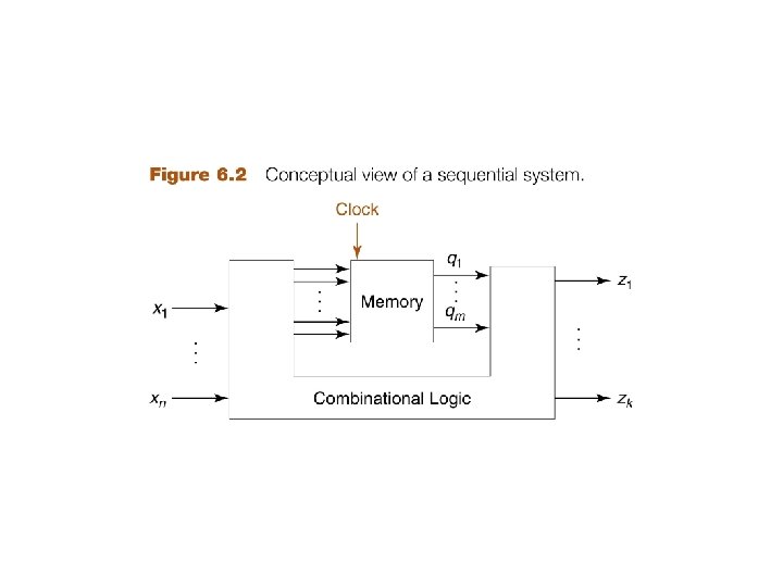
Engineering Takes three approaches 1. Analysis – looks at a system to determine how it works 2. Design – looks at how to make a system 3. Application – looks at integration of existing designs for solution Chapter 6 is analysis Chapter 7 is design Combinational logic uses AND, OR, NOT to create circuit. Sequential logic uses Flip / Flops to create memory. Usually adds combinational as input and output to the memory.
Asynchronous - USB Synchronous – Cell phone “ON” duration can vary Pulse is often choice Power depends on “ON” duration Time Clock Enable Simply another input Frequency = 1/T 200 MHz = 50 microsec Leading edge – active high Trailing or falling edge – active low Signal is active as approaches active level Transition not sharp, but has slope
CE 6. A system with one input x and one output z such that z = 1 iff x has been 1 for at least three consecutive clock times. State: what is stored in memory. It is stored in binary devices, but the information to be stored is not always naturally binary. Timing trace: a set of values for the input and output (and sometimes the state or other variables of the system, as well) at consecutive clock times.
State table: shows for each input combination and each state, what the output is and what the next state is, that is, what is to be stored in memory after the next clock. State diagram (or state graph): a graphical representation of the state table. Moore machine output occurs at next state Requires one more state (FF) but less logic
Mealy machine output occurs at present state + input Requires one less state (FF) but more logic
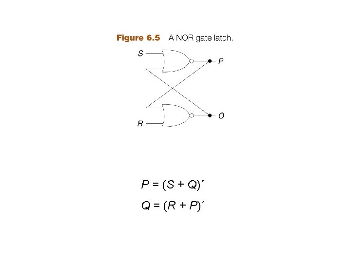
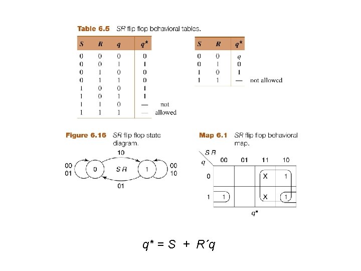
Flip Flops / Latch S = Set R = Reset When S=0, R=1, Qt+1 = 0 When S=1, R=0, Qt+1 = 1
Asynchronous (RS F/F) Characteristic Table Excitation Table Characteristic Eq. Symbol Circuit
Characteristic Table Excitation Table Characteristic Eq. Synchronous Symbol Circuit
Flip flop is a latch triggered by a clock 1. Has feedback 2. Is memory device 3. Holds the state Q’ S = set, output q=1 R = reset, output q=0 Q = (R + P)´ Q’ = (S + Q)´
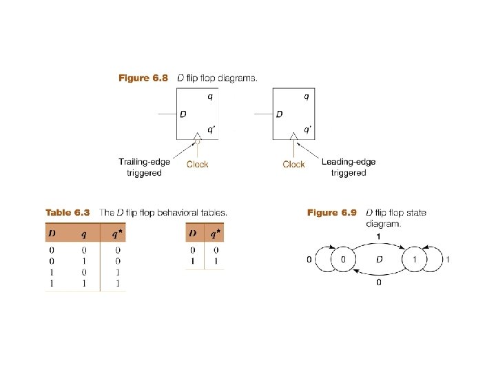
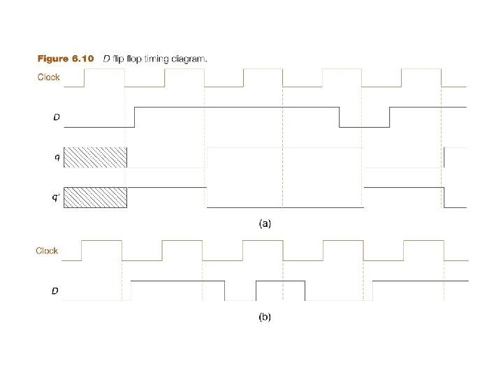
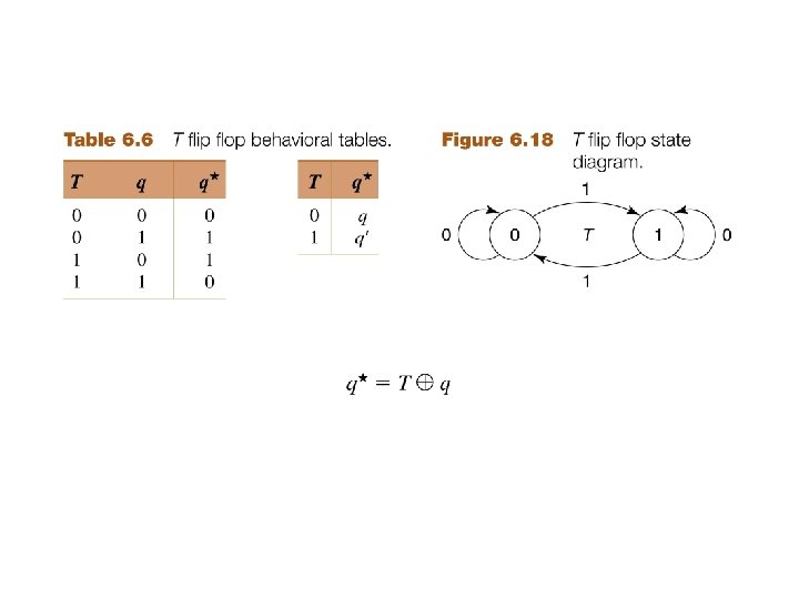
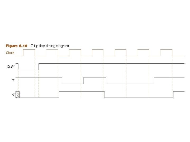
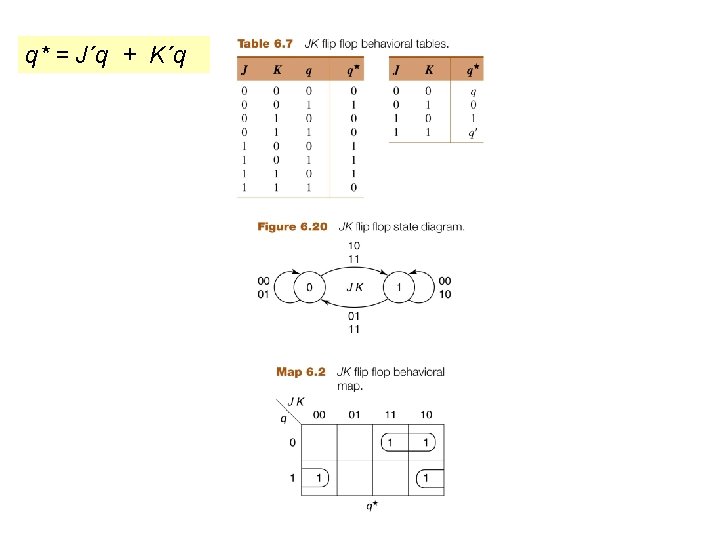
F/F designs SR is the basic device Q indeterminant w/ SR=11 JK uses feedback to fix D is delay D into S & D’ into R T is toggle T into both J & K Q’
D 1 = q 1 q´ 2 + x q´ 1 D 2 = xq 1 z = q´ 2
D 1 = q 1 q´ 2 + x q´ 1 D 2 = xq 1 z = q´ 2 PS q 1 q 2 00 01 10 11 x=0 D 1 D 2 0 0 1 0 x=1 D 1 D 2 1 1 1 0 x=0 q 1*q 2* 0 0 1 0 x=1 q 1*q 2* 1 1 1 0 z 1 1 0 0
D 1 = q 1 q´ 2 + x q´ 1 D 2 = xq 1 z = q´ 2 PS q 1 q 2 00 01 10 11 x=0 D 1 D 2 00 00 10 00 x=1 D 1 D 2 10 10 11 01 x=0 q 1*q 2* 00 00 10 00 x=1 q 1*q 2* 10 10 11 01 z 1 1 0 0 Moore: Output depends Only on state, So show out inside state
J 1 = x K 1 = x. B´ J 2 = K 2 = x + A´ z=A+B Moore machine, output z does not depend on input x
J 1 = x K 1 = x. B´ J 2 = K 2 = x + A´ z=A+B PS AB 00 01 10 11 1. 2. 3. 4. 5. 6. 7. 8. x=0 J 1 K 1 00 00 x=1 J 2 K 2 11 11 00 00 J 1 K 1 Row 1, look at both A(1) B(2) Start w/ x=0 PS, A=0 B=0 (Qa=0 Qb=0) J 1=K 1=0 J 2=K 2=1 Then from table get NS J 1=0, K 1=0→ A*=A=0 J 2=1, K 2=1 →B*=B’=1 J 2 K 2 x=0 A*B* 01 00 1. 2. 3. 4. 5. 6. 7. 8. x=1 A*B* z 0 1 1 1 Row 2 Start w/ x=0 PS, A=0 B=1 (Qa=0 Qb=1) J 1=K 1=0 J 2=K 2=1 Then from table get NS J 1=0, K 1=0→ A*=A=0 J 2=1, K 2=1 →B*=B’=0
J 1 = x K 1 = x. B´ J 2 = K 2 = x + A´ z=A+B PS AB 00 01 10 11 1. 2. 3. 4. 5. x=0 J 1 K 1 00 00 x=1 J 2 K 2 11 11 00 00 J 1 K 1 11 10 x=0, look at A (1) only J 1=K 1=0 J 2=K 2=1 Then from table get NS J 1=0, K 1=0→ A*=A J 2 K 2 11 11 x=0 A*B* 0 0 1 1 1. 2. 3. 4. 5. 6. x=1 A*B* 1 1 0 1 z 0 1 1 1 x=1, look at A (1) only J 1=1, K 1=B’ When B=0, J 1=K 1 A=Toggle When B=1, J 1=1, Ka=0 A=1
J 1 = x K 1 = x. B´ J 2 = K 2 = x + A´ z=A+B PS AB 00 01 10 11 x=0 J 1 K 1 00 00 x=1 J 2 K 2 11 11 00 00 1. 2. 3. 4. 5. 6. 7. J 1 K 1 11 10 J 2 K 2 11 11 x=0 A*B* 01 00 10 11 look at B (2) only When A=0, J 2=K 2=1 B*=toggle When A=1, J 2=K 2=x for x=0, B*=B for x=1, B*=toggle J 1=0, K 1=0→ A*=A x=1 A*B* 11 10 01 11 z 0 1 1 1
J 1 = x K 1 = x. B´ J 2 = K 2 = x + A´ z=A+B PS AB 00 01 10 11 x=0 J 1 K 1 00 00 x=1 J 2 K 2 11 11 00 00 J 1 K 1 11 10 J 2 K 2 11 11 x=0 A*B* 01 00 10 11 x=1 A*B* 11 10 01 11 z 0 1 1 1
J 1 = x K 1 = x. B´ J 2 = K 2 = x + A´ z=A+B Alternative is use Boolean equations For J-K f/f q*=Jq’ + K’q For this problem A* = Ja. A’ + Ka’A = x. A’ + (x. B’)A = x. A” + x’A + AB B* = Jb’ + Kb’B = (x + A’)B’ + (x + A’)B = x. B’ + A’B’ + x’AB PS AB 00 01 10 11 x=0 J 1 K 1 00 00 x=1 J 2 K 2 11 11 00 00 J 1 K 1 11 10 J 2 K 2 11 11 x=0 A*B* 01 00 10 11 x=1 A*B* 11 10 01 11 z 0 1 1 1
D 1 = xq 1 + xq 2 D 2 = xq´ 1 q´ 2 z = xq 1 Mealy, output z depends on input x, as well as state variables (F/F) So state table will have output for x=0 & for x=1 D f/f, q* = D q 1* = xq 1 + xq 2 q 2* = xq´ 1 q´ 2
D 1 = xq 1 + xq 2 D 2 = xq´ 1 q´ 2 z = xq 1 PS q 1 q 2 00 01 10 11 x=0 D 1 D 2 00 00 x=1 D 1 D 2 01 10 10 10 x=1 x=0 x=1 q 1*q 2* z 00 01 0 0 00 10 0 1 State 11 is never reached Mealy: Output depends on state & input, So show out on transition
D 1 = xq 1 + xq 2 PS q 1 q 2 00 01 10 11 x=0 D 1 D 2 00 00 x=1 D 1 D 2 01 10 10 10 x=1 x=0 x=1 q 1*q 2* z 00 01 0 0 00 10 0 1 D 2 = xq´ 1 q´ 2 z = xq 1 Glitch z = x q 1 x=1 after q 1=1 Fixed by next clock