Attitude Control of Satellites MAE 506 Advanced System
")


’ Q")


 Figure 5. Command Torques")


 Figure 10. Command Torques in")


![References [i] www. isro. gov. in](https://slidetodoc.com/presentation_image_h2/5e8be7e9467e2f0a5dba942f03b28cb3/image-20.jpg "References [i] www. isro. gov. in")
- Slides: 20
Attitude Control of Satellites MAE 506: Advanced System Modeling, Dynamics and Control (Fall 2019) Project Presentation by - Mitul Magu, Mohit Bhagwat, Nan Xu
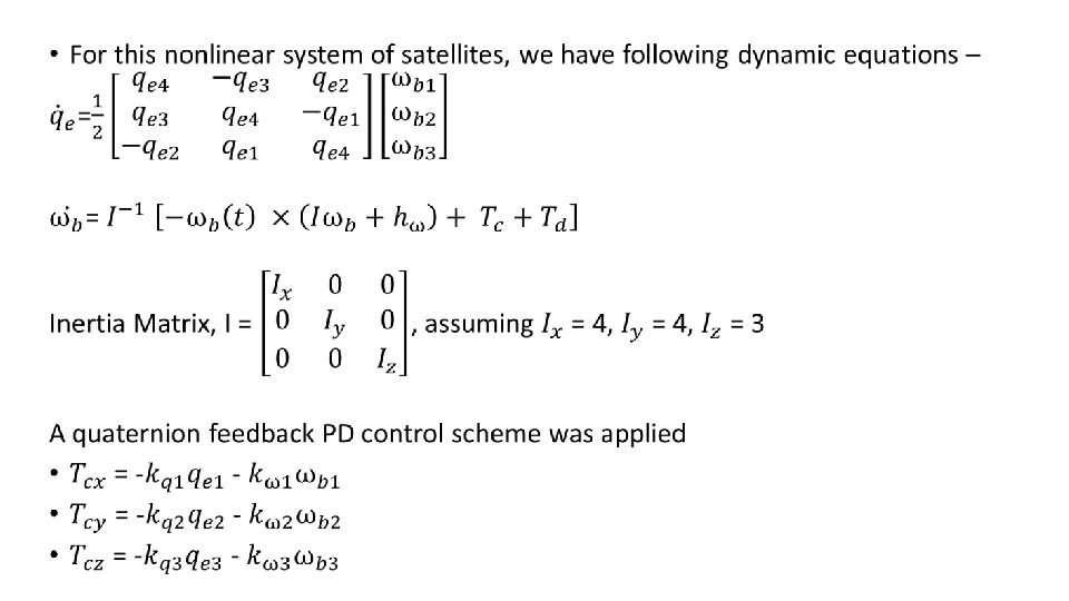
Background • Several subsystems of a satellite requires stability to get a better performance from payloads – 1. Reorienting antennas or telescopes towards a specified direction. 2. Keeping solar panels in the correct position relative to sun rays in order to absorb maximum energy. • High pointing accuracy and reliability are the most important problems of the attitude control system designs. [i]
Goal • To design a model for the attitude control of a satellite using the pyramid configuration of the reaction wheels. • We then want to optimize the control system using the Quaternion Feedback PD controller using a gain matrix from the ‘Linear Quadratic Regulator’ (LQR) strategy and also the ‘Sliding Mode Controller ’.
State Space Model for LQR Controller •
Linearizing the System •
Feedback Gain for the LQR Controller •
SIMULINK MODEL System Dynamics: SIMULINK MODEL
Sliding Mode Controller Sliding Surface : Control Law : G= K, minimize(J=∫ [x(τ)’ Q x(τ) + u(τ)’ R u(τ)] dτ) G, greater than Wb K=
Sliding Mode Controller Figure 2. SIMULINK Sketch of Sliding Mode Controller
Simulation and Result ● Results of Sliding Mode Controller Figure 3. Response of Euler Angles Figure 4. Response of Angular Velocities in 3 -axis
Simulation and Result ● Results of Sliding Mode Controller (Contn) Figure 5. Command Torques in 3 -axis Figure 6. Torque Generated by Each Reaction Wheel
LQR Controller ● For the nonlinear system of satellites, we assume can define , when. ● We can linearize and discretize the system about are smoothly differentiable, We and get eq. (6) where i indicates number of the sample time. For each discretized system, it must be stabilizable and the local linearized optimal cost function to be minimized is in eq. (7) S will be calculated by Riccati Equation as. If the boundary condition of S = Q, the optimal input can be calculated by eq. (8) ● Since this system always ends up following if inertia matrix is. , the gains obtained for this system is
Simulation and Result ● The SIMULINK Sketch of LQR Controller is shown as follows Figure 7. SIMULINK Sketch of LQR Controller
Simulation and Result ● Results of LQR controller Figure 8. Response of Euler Angles Figure 9. Response of Angular Velocities in 3 -axis
Simulation and Result ● Results of LQR controller (Contn) Figure 10. Command Torques in 3 -axis Figure 11. Torque Generated by Each Reaction Wheel
Comparison and Conclusion ● The time of LQR system reaches the desired Euler angle is 80 seconds and power consumption is 0. 00035 W. ● The time of SMC system reaches the desired Euler angle is 40 seconds and power consumption is 0. 00073 W. ● The SMC system is faster than LQR system but SMC system will use more energy than LQT system. In the aerospace industry, it will be better to use LQR system to save energy.
Thank You! Please feel free to ask any questions
References [i] www. isro. gov. in