Antenna Tuners Do Not Tune Antennas Hap Griffin


- Slides: 40
Antenna Tuners Do Not Tune Antennas Hap Griffin SARA August 2016
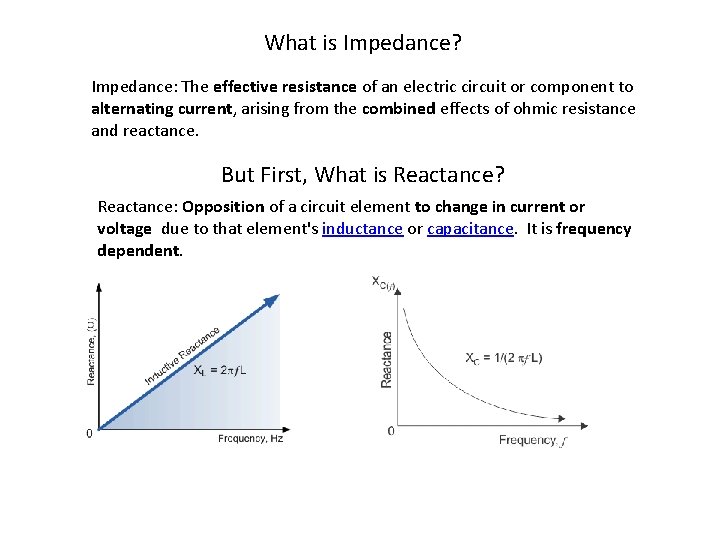
What is Impedance? Impedance: The effective resistance of an electric circuit or component to alternating current, arising from the combined effects of ohmic resistance and reactance. But First, What is Reactance? Reactance: Opposition of a circuit element to change in current or voltage due to that element's inductance or capacitance. It is frequency dependent.
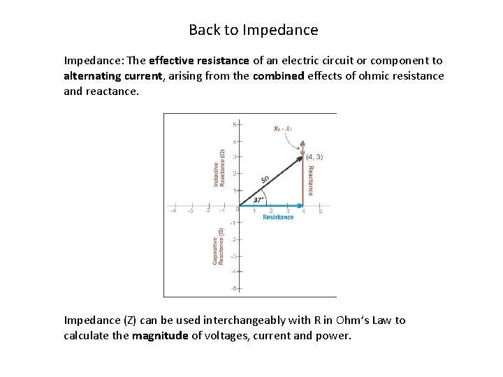
Back to Impedance: The effective resistance of an electric circuit or component to alternating current, arising from the combined effects of ohmic resistance and reactance. Impedance (Z) can be used interchangeably with R in Ohm’s Law to calculate the magnitude of voltages, current and power.
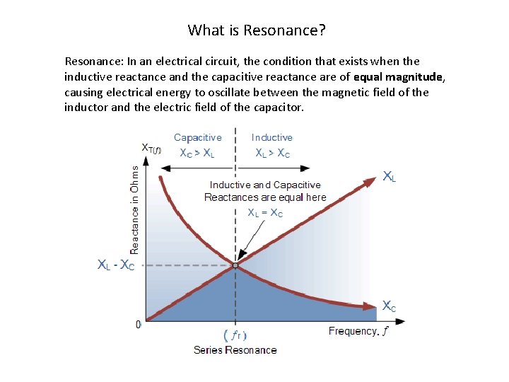
What is Resonance? Resonance: In an electrical circuit, the condition that exists when the inductive reactance and the capacitive reactance are of equal magnitude, causing electrical energy to oscillate between the magnetic field of the inductor and the electric field of the capacitor.
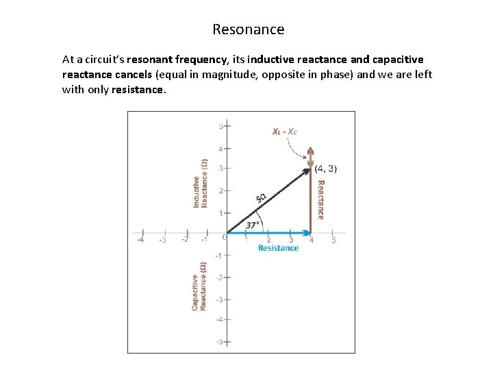
Resonance At a circuit’s resonant frequency, its inductive reactance and capacitive reactance cancels (equal in magnitude, opposite in phase) and we are left with only resistance.
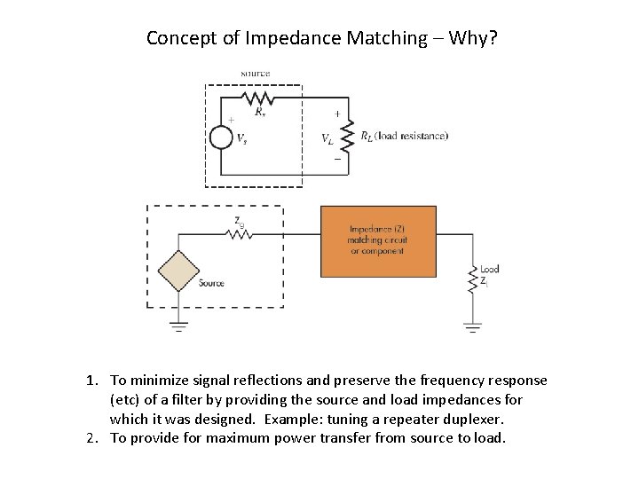
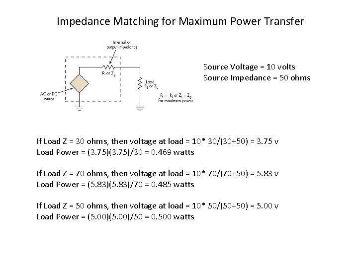
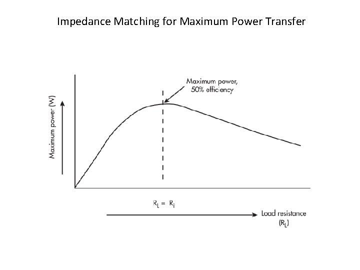
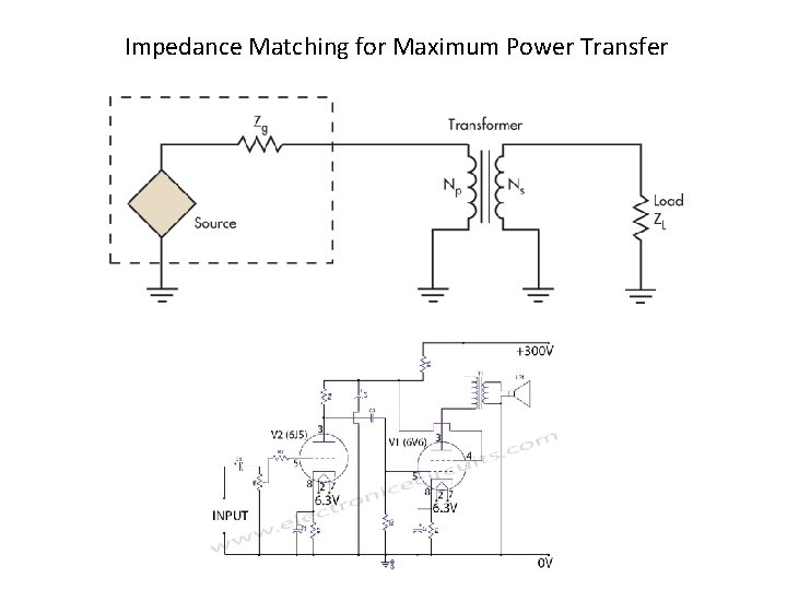
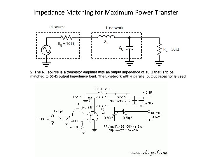
Concept of Impedance Matching – Why? 1. To minimize signal reflections and preserve the frequency response (etc) of a filter by providing the source and load impedances for which it was designed. Example: tuning a repeater duplexer. 2. To provide for maximum power transfer from source to load.
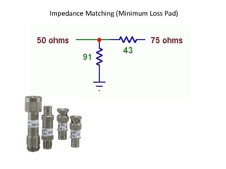
Impedance Matching (Minimum Loss Pad)
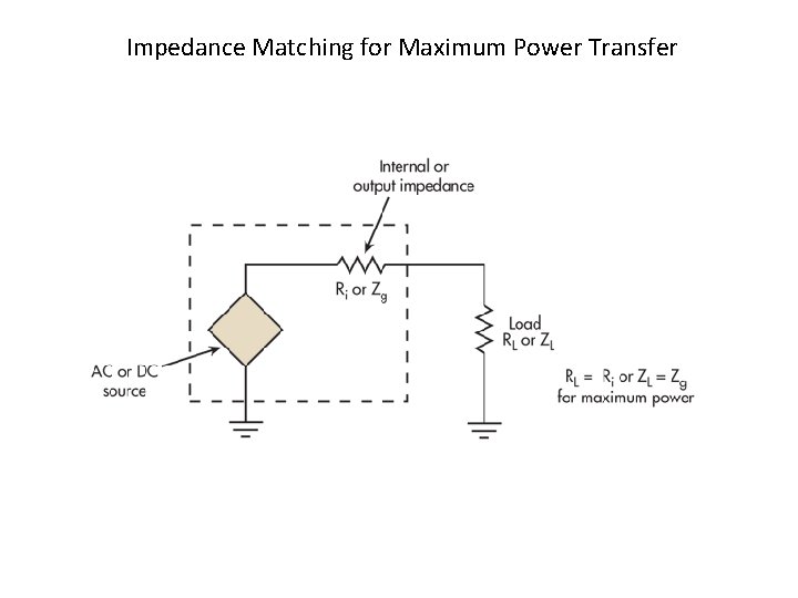
Impedance Matching for Maximum Power Transfer
Impedance Matching for Maximum Power Transfer Source Voltage = 10 volts Source Impedance = 50 ohms If Load Z = 30 ohms, then voltage at load = 10* 30/(30+50) = 3. 75 v Load Power = (3. 75)/30 = 0. 469 watts If Load Z = 70 ohms, then voltage at load = 10* 70/(70+50) = 5. 83 v Load Power = (5. 83)/70 = 0. 485 watts If Load Z = 50 ohms, then voltage at load = 10* 50/(50+50) = 5. 00 v Load Power = (5. 00)/50 = 0. 500 watts
Impedance Matching for Maximum Power Transfer
Impedance Matching for Maximum Power Transfer
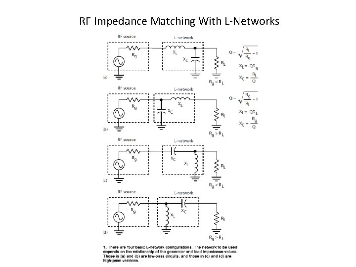
RF Impedance Matching With L-Networks
Impedance Matching for Maximum Power Transfer
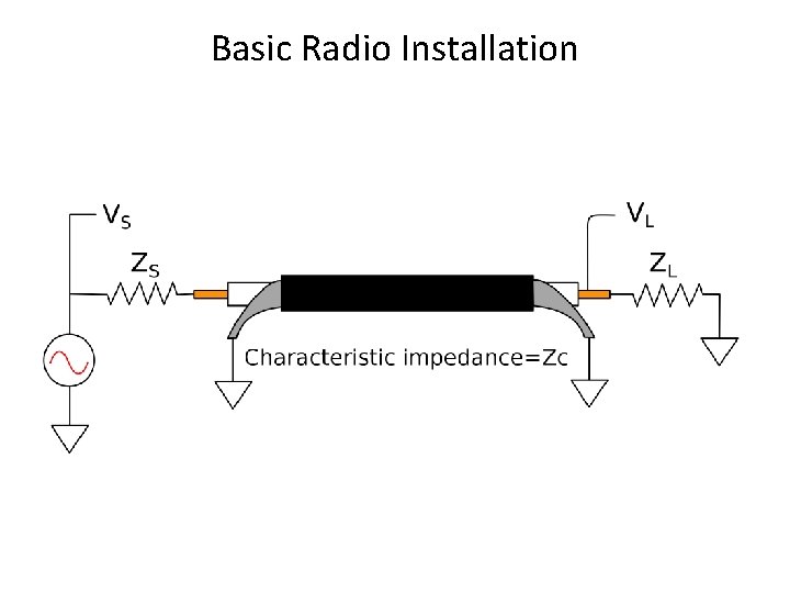
Basic Radio Installation
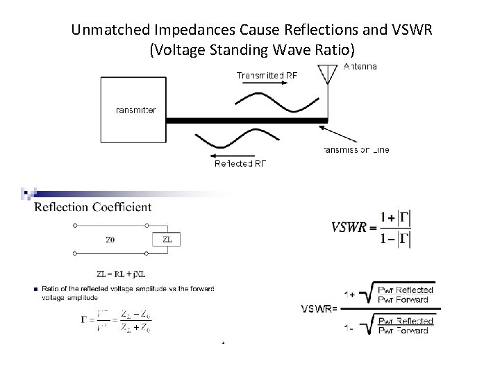
Unmatched Impedances Cause Reflections and VSWR (Voltage Standing Wave Ratio)
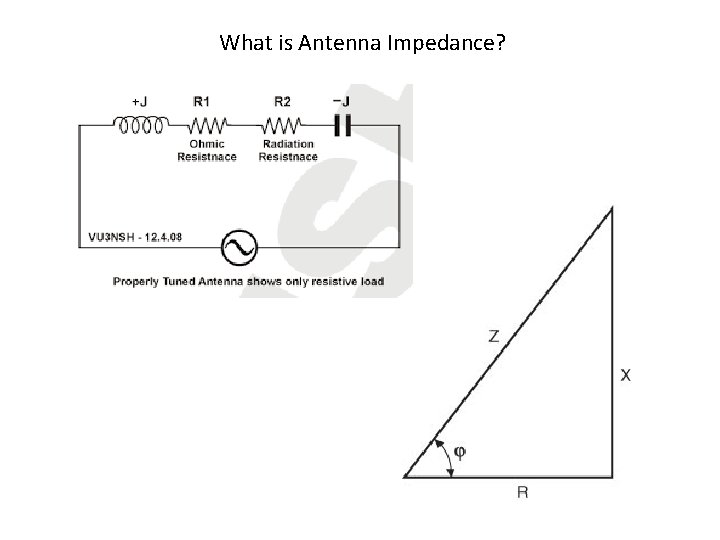
What is Antenna Impedance?
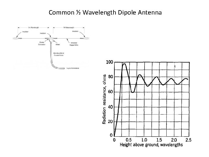
Common ½ Wavelength Dipole Antenna
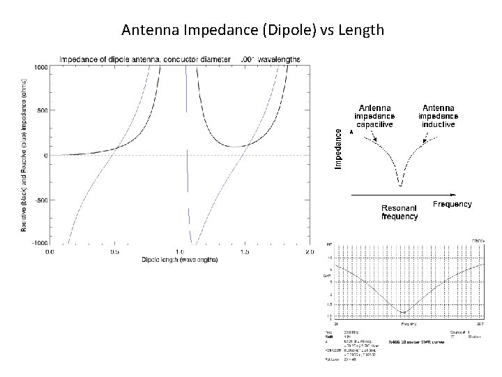
Antenna Impedance (Dipole) vs Length
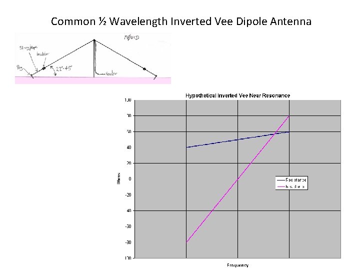
Common ½ Wavelength Inverted Vee Dipole Antenna
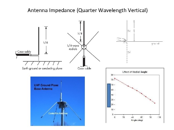
Antenna Impedance (Quarter Wavelength Vertical)
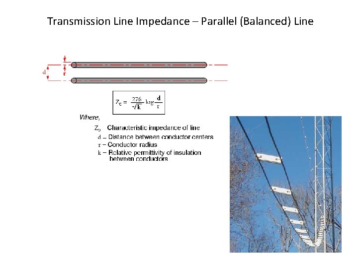
Transmission Line Impedance – Parallel (Balanced) Line
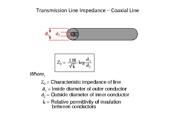
Transmission Line Impedance – Coaxial Line
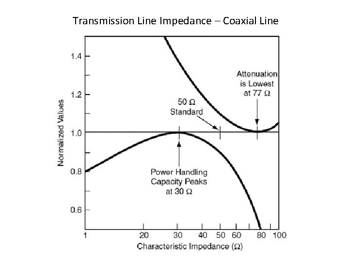
Transmission Line Impedance – Coaxial Line
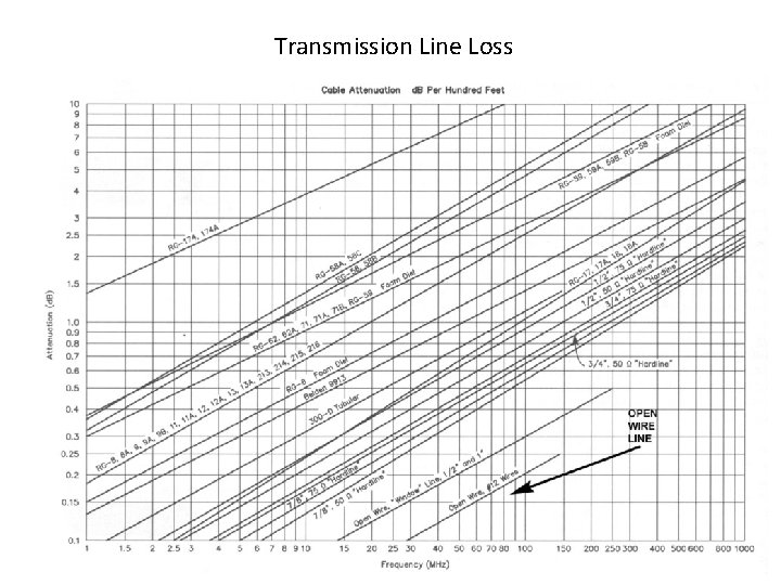
Transmission Line Loss
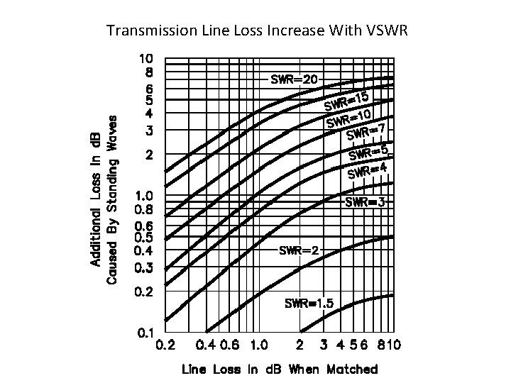
Transmission Line Loss Increase With VSWR
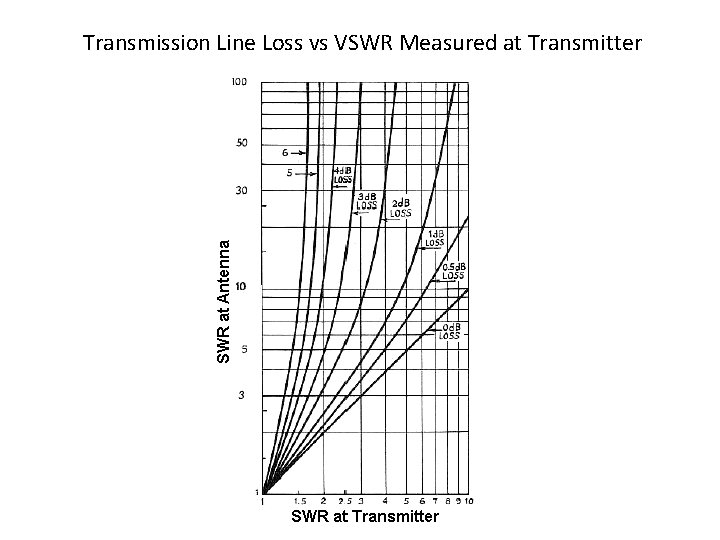
Transmission Line Loss vs VSWR Measured at Transmitter
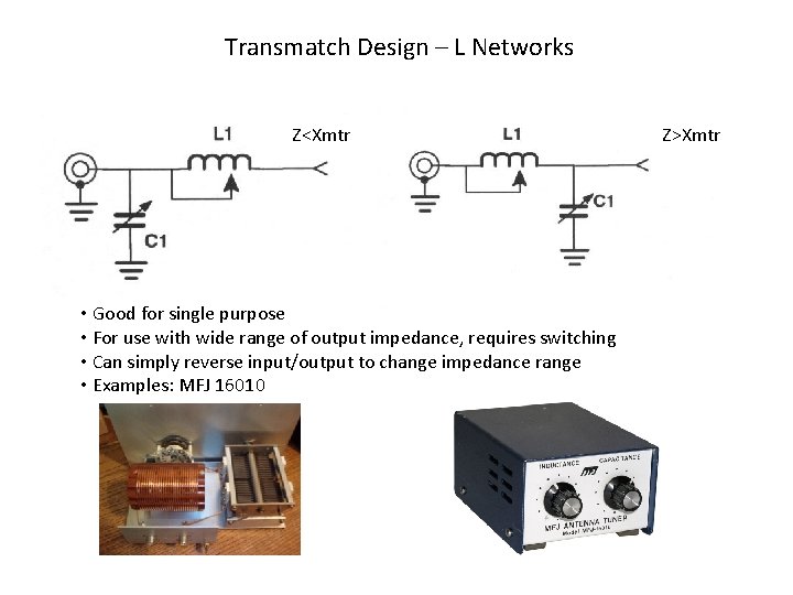
Transmatch Design – L Networks Z<Xmtr • Good for single purpose • For use with wide range of output impedance, requires switching • Can simply reverse input/output to change impedance range • Examples: MFJ 16010 Z>Xmtr
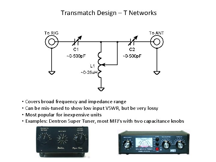
Transmatch Design – T Networks • Covers broad frequency and impedance range • Can be mis-tuned to show low input VSWR, but be very lossy • Most popular for inexpensive units • Examples: Dentron Super Tuner, most MFJ’s with two capacitance knobs
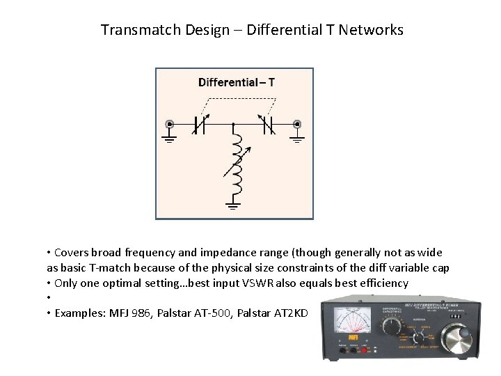
Transmatch Design – Differential T Networks • Covers broad frequency and impedance range (though generally not as wide as basic T-match because of the physical size constraints of the diff variable cap • Only one optimal setting…best input VSWR also equals best efficiency • • Examples: MFJ 986, Palstar AT-500, Palstar AT 2 KD
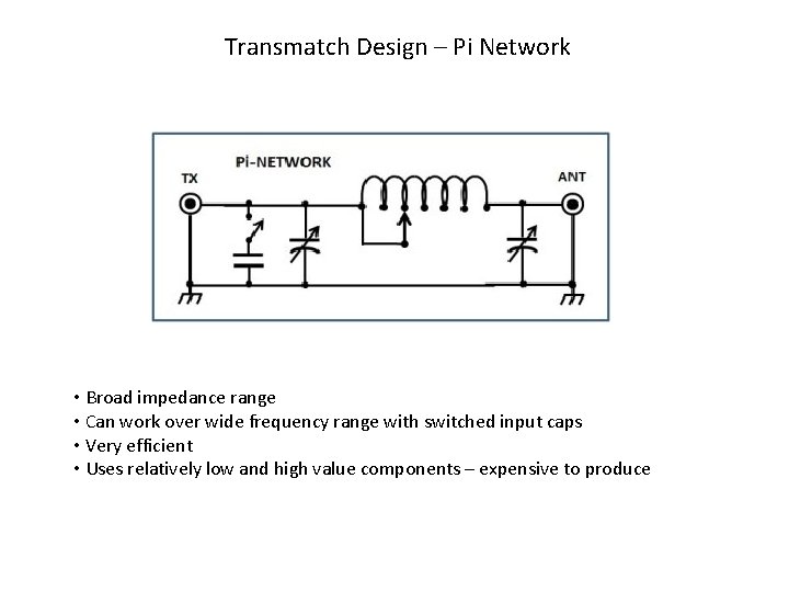
Transmatch Design – Pi Network • Broad impedance range • Can work over wide frequency range with switched input caps • Very efficient • Uses relatively low and high value components – expensive to produce
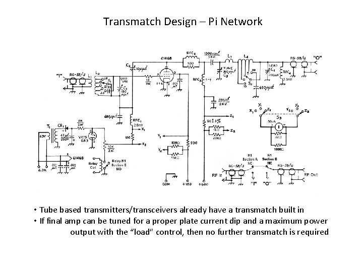
Transmatch Design – Pi Network • Tube based transmitters/transceivers already have a transmatch built in • If final amp can be tuned for a proper plate current dip and a maximum power output with the “load” control, then no further transmatch is required
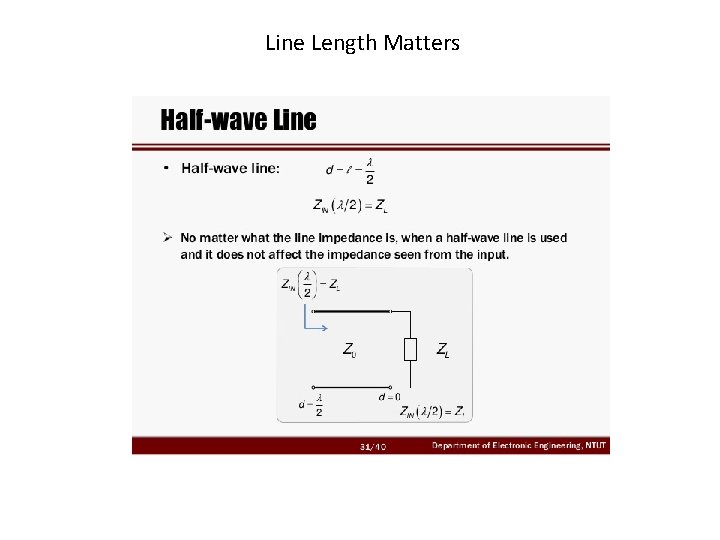
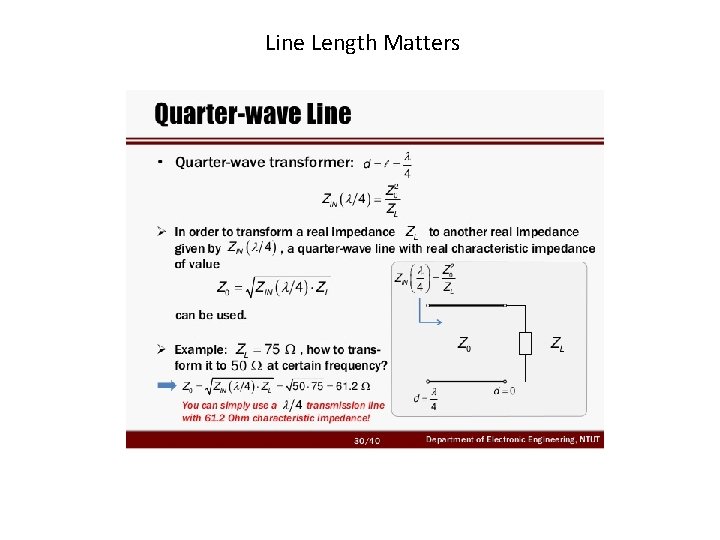
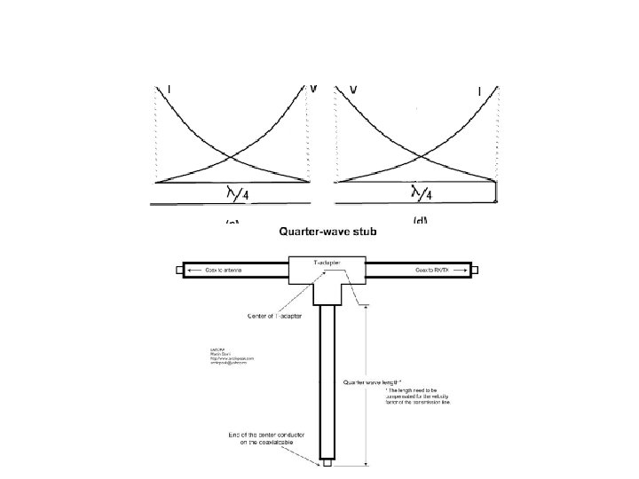
Line Length Matters
Line Length Matters
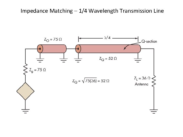
Impedance Matching – 1/4 Wavelength Transmission Line
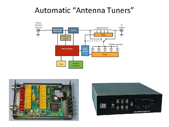
Automatic “Antenna Tuners”
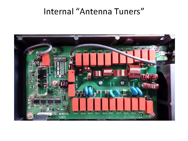
Internal “Antenna Tuners”
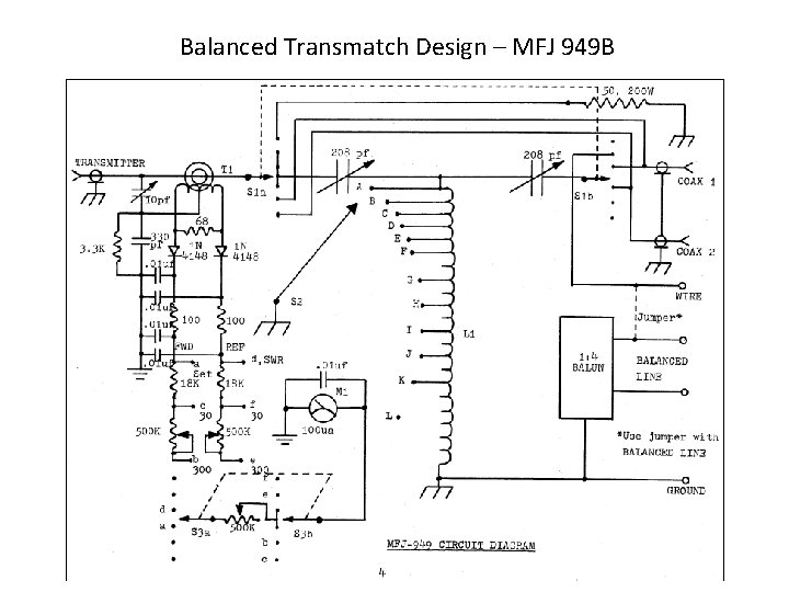
Balanced Transmatch Design – MFJ 949 B
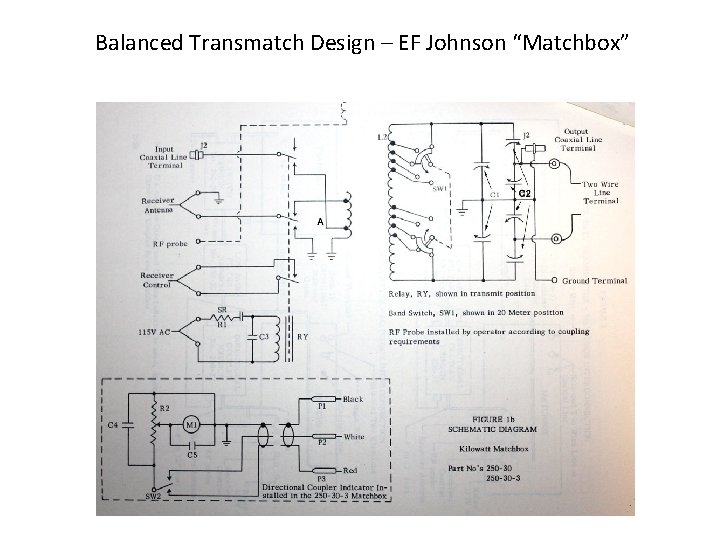
Balanced Transmatch Design – EF Johnson “Matchbox”
Remote Antenna Tuners