4 CRS SANCTION SCHEDULE OF 11 DIMENSIONS 4


 In case of tunnels, ROBs, flyovers, through &")
")


 Minimum distance of centre")
Minimum horizontal distance from centre")
Minimum horizontal distance from centre")
Minimum horizontal distance from centre")
Minimum horizontal distance from centre")


Increase due to extra ballast")
Increase on double line")


Recommended dimension is generally")
In case, it")
No station yard")
The power of")
 For above")
 There must")
 Horizontal distance from centre of track to face of passenger platform")
Horizontal distance from centre of track to face of goods platform")
 New platform walls should be built to maximum")

Platforms may be flush with rail")
End loading platforms and platforms")
No passenger platform in case")
For Item 4: the height")


 1 in 16 •")


- Slides: 62
4 CRS SANCTION & SCHEDULE OF 11 DIMENSIONS 4. 2 Various schedules of dimensions 4 related to P. Way
What is SOD • Schedule of dimension is nothing but a schedule, which lays down : • Limiting values, recommended values, and infringement to limiting values, which can be continued over entire Indian railways system for various track parameters unless prior sanction has been obtained from the railway board through the CRS to execute works which infringe SOD. • Goods wagon and coaching stock parameters. • Horizontal and vertical clearances to be followed on Indian railways.
Necessity of S O D • It is absolutely essential to ensure safety of traveling public as well as goods over entire Indian railways system. • To adopt uniform system of track tolerances, location of structures and construction standard all over the Indian railways. • To permit different types of coaching and goods stock owned by different railways to ply on entire railway system with same level of degree of safety.
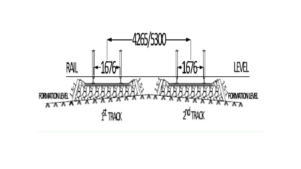
GENERAL Spacing of Tracks For existing works For new works/additions to existing works 4265 mm 5300 mm Note: (a) Extra clearance required on curves. (b) Spacing of tracks in tunnels, Road Over Bridges/Flyovers, through and semi through girder bridges are different. (c) New/Additional works cover laying of new line and new running loops. Extension of existing line or replacement of points & crossings will not be treated as new work.
GENERAL … Spacing of Tracks For existing works For new works/additions to existing works 4265 mm 5300 mm Note: (d) OHE mast and Signal post shall not preferably be provided in between tracks. However, under unavoidable circumstances, the clearance maintained in Para 1 (ii) above shall be increased by equal to the width of such provisions/structures/foundation, as the case may be.
GENERAL … Spacing of Tracks. (e) In case of tunnels, ROBs, flyovers, through & semi-through girder bridges, where centre to centre distance, lesser than 5300 mm has been provided, lesser centre to centre distance can be provided on approaches also up to adequate distance to facilitate gradual increase in centre to centre distance up to 5300 mm.
GENERAL … Curves • Minimum radius of curves: 175 m (10 degrees)
GENERAL … Bridges • Bridges must conform to the requirements of chapter IV of the Railways opening for the Public carriage of Passengers, Rule 2000. • Directly on longitudinal girders should not be less than 150 mm deep exclusive of any notching which may be required to allow for cover plates, camber, etc. and not less than 305 mm greater in length than the distance On existing bridges where there is nothing solid between sleepers to prevent a derailed wheel dropping. • The clear distance between two consecutive sleepers shall not exceed 510 mm.
Bridges … GENERAL … • The clear distance between the joint sleepers shall not, however, exceed 200 mm and that between the two consecutive sleepers 450 mm in all new constructions and in existing bridges when regirdering or carrying out through sleeper renewal. • Bridge sleepers resting outside to outside of girder flanges subject to a minimum of 2440 mm. • The minimum length of steel trough sleepers should be the distance outside to outside of girder flanges subject to a minimum of 2440 mm.
Rails: GENERAL … • 4. Minimum clearance of check rails for a curve: 44 mm Note: • (a)This clearance must be increased by not less than half the amount of any difference between 1676 mm and the gauge to which the curve is actually laid. • (b) Check rails to be provided in curves where the radius is 218 m or less i. e. curvature is 8° or more. They may be necessary also in the case of flatter curves, if high speed is contemplated. Minimum clearance of check rail at a level crossing Maximum clearance of check rail at a level crossing Minimum depth of space for wheel flange from rail level 51 mm 57 mm 38 mm
GENERAL … • Minimum horizontal distance of any telegraph post measured from the centre of and at right angles to the nearest track. For existing works For new works or alterations to existing works The height of the post + 2135 mm The height of the post + 2360 mm Note: When the line is in cutting a telegraph post erected outside the cutting, must be at a distance from the edge of the cutting not less than the total height of the post.
GENERAL … • Height of Road Over Bridges and Foot Over Bridges Minimum height above rail level for a distance of 915 mm on either side of the centre of track for overhead structures 4875 mm Where 25 KV A. C. traction is likely to be used, the 5140 mm minimum height above rail level for a distance of 1600 mm on either side of the centre of track shall be as under: i)Light overhead structure such as Foot Over Bridges 6250 mm ii)Heavy overhead structure such as Road Over Bridges 5870 mm and Flyovers
GENERAL … • Height of Road Over Bridges and Foot Over Bridges … • Note: • (a) Extra clearance required on curves. • (b)In case of restricted height of existing structures, a special study shall be made, as indicated in Appendix-A to Chapter V-A before 25 k. V AC traction is introduced. Accordingly, only in such cases, the minimum height above rail level shall not be lower than 5070 mm in case of Heavy Overhead Structure (such as Road Over& Flyovers) and 5270 mm in case of Light Overhead Structures (such as Foot Over Bridges) for a minimum contact wire height of 4800 mm from above rail level. OHE arrangements shall be as per RDSO Drawings.
GENERAL … • Height of Road Over Bridges and Foot Over Bridges … • Note: …. • (c)In areas where 25 KV A. C traction is used or likely to be used, if any turnout or crossover is located under a heavy overhead structure or within 40 m from its nearest face irrespective of the position of level crossing gate, the minimum height of such overhead structure shall be 6250 mm*. Also, in case the turnout is beyond 40 m but the level crossing gate is within 520 m from the nearest face of the bridge, the height of such overhead structure shall be 6250 mm*. • (d)The height mentioned against items 10(a), 10(b) & 10(c) shall be measured from the higher or super-elevated rail.
GENERAL … • Height of Road Over Bridges and Foot Over Bridges … • Note: …. • (e)On lines existing or proposed to be electrified on 25 KV A. C. system, necessary provision should be made in overhead structure and overhead equipment, if necessary by using longer traction overhead equipment masts to permit an extra allowance of 275 mm for raising of track in connection with the introduction of modern track structure in future to cater for modern track structure in the form of increased ballast cushion, larger sleeper thickness and deeper rail sections • *(In case of restricted height of existing heavy overhead structure, minimum height above rail level shall not be lower than 5270 mm, adhering to the provisions of note (b) above). (CS No. 13)
GENERAL … • Height of Road Over Bridges and Foot Over Bridges … • Note: …. • (f)For Mumbai Suburban, the height of Foot Over Bridges mentioned under para 10(c)(i) above maybe reduced to 5750 mm subject to following conditions: • i. The minimum height of the contact wire shall be 4800 mm. • ii. A special study shall be conducted as indicated in appendix A of chapter V-A to ascertain the feasibility of the contact wire height as 4800 mm.
GENERAL … • Height of Road Over Bridges and Foot Over Bridges … • Note: …. • iii. There shall be no crossover below FOB or within 40 m from the face of FOB. • iv. There shall be no level crossing within 520 m from face of FOB. • v. The maximum height of rolling stock shall be restricted to 4420 mm. • vi. The height shall be measured from the higher or super-elevated rail.
GENERAL … Tunnels, through and semi-through girder bridges: — (i) Minimum distance of centre to centre of track a)For existing lines 4495 mm b)For new works and alteration to existing works 4725 mm
GENERAL … Tunnels, through and semi-through girder bridges: — (ii)Minimum horizontal distance from centre of track to any structure shall be as follows: Height Above Rail Level From 0. 0 mm to 305 mm From 305 mm to 1065 mm From 1065 mm to 3355 mm From 3355 mm to 4420 mm From 4420 mm to 5870 mm Horizontal Distance From Centre Of Track 1905 mm increasing to 2360 mm decreasing to 2135 mm 2135 mm decreasing to 915 mm
GENERAL … Tunnels, through and semi-through girder bridges: — (ii)Minimum horizontal distance from centre of track to any structure shall be as follows: …. Note: • i. Where electric traction is not likely to be used, over head bracing of bridges may be 5030 mm above rail level for a distance of 1370 mm on either side of the centre of track. • ii. In case of existing structures, a special clearance study shall be made as indicated in Appendix -A to Chapter V-A before electric traction is introduced. • iii. See Appendix for extra clearances required on curves.
GENERAL … Tunnels, through and semi-through girder bridges: — (ii)Minimum horizontal distance from centre of track to any structure shall be as follows: …. Note: • iv. Where D. C. traction is in use item 13(ii)(e) above may be as under: • From 4420 mm to 5410 mm : 2135 mm decreasing to 915 mm
GENERAL … Tunnels, through and semi-through girder bridges: — (ii)Minimum horizontal distance from centre of track to any structure shall be as follows: …. Note: • v. Tunnels , through girder and semi through girder bridges outside station yards should be treated as heavy over head structures such as ROB for electrification works and the same dimension as mentioned in note (c) at Para 10 above shall be applicable and OHE arrangement shall be as per RDSO drawing.
GENERAL … Tunnels, through and semi-through girder bridges: —
GENERAL … Tunnels, through and semi-through girder bridges: —
GENERAL … Safety Refuges : — Maximum distance apart of refuges in tunnels Maximum distance apart of trolley refuges : i. On bridges with main spans of less than 100 m ii. On bridges with main spans of 100 m or more 100 m A refuge over each pier
GENERAL … Formation width : — Formation width for single line straight track i. ii. For existing works a. Minimum width in embankment b. Minimum width in cutting (excluding side drains) For new works/alteration to existing works a. Minimum width in embankment b. Minimum width in cutting (excluding side drains) 6850 mm 6250 mm 7850 mm
GENERAL … Formation width : — Formation width for double line straight track i. For existing works a. Minimum width in embankment b. Minimum width in cutting (excluding side drains) The minimum formation width is based on : ii. For new works/alteration to existing works a. Minimum width in embankment b. Minimum width in cutting (excluding side drains) 12150 mm 11550 mm 13160 mm
GENERAL … Formation width : — Formation width for double line straight track Note : The minimum formation width is based on : i. Ballast section having 1. 5: 1 side slope. ii. Cross slope on top of formation of 1 in 30. iii. Track centre in case of double line section is 5300 mm.
GENERAL … • Formation width on curves : • (a)Increase due to extra ballast on outside of curves: • On curves, the actual width to be provided should take into account 150 mm extra widening of ballast shoulder (500 mm in place of 350 mm) required on the outer side of curves. Thus, additions in the width on this account will be 150 mm for single line and 300 mm for double line.
GENERAL … • Formation width on curves : … • (b)Increase on double line due to effect of super-elevation: • Due to requirement of extra clearances on double line on curves, increase in track centers with corresponding increase in formation width would be necessary to take into account the effect of super elevation. • Increase in formation width on curves will be decided after taking - into account the increase mentioned in (a) & (b) above
GENERAL … • Gauge on straight and curves : • The gauge shall be as follows: Straight including curves of radius -5 mm to +3 mm 350 m or more i. e 1671 mm to 1679 mm For Curves of radius less than 350 m Upto+10 mm i. e. 1686 mm
Maximum steepest gradient in station yards • Maximum steepest gradient in station yards, unless special safety devices are adopted and/orspecial rules enforced to prevent accidents in accordance with approved special instructions. (i)For New works & Alteration to Existing Worksa)Recommended 1 in 1200 (0. 083%) (b)Maximum (Steepest) 1 in 400 (0. 25% ) (ii)For existing works 1 in 400 (0. 25% )
Maximum steepest gradient in station yards … • Note: • (a)Recommended dimension is generally the good practice, the adoption of which will lead to desirable uniformity on Indian Railways, but it is not to be treated as standards, a departure from which requires sanction.
Maximum steepest gradient in station yards … • Note: … • (b)In case, it is not possible to provide recommended gradient of 1 in 1200 (0. 083%) in yard even after making efforts to provide grades as flat as possible, reason for deviation from recommended gradient and up to the specified maximum (steepest) gradient of 1 in 400 (0. 25%) shall be recorded on the ESP. However, for new yards in new line projects adoption of yard gradient steeper than 1: 1200 will require the approval of General Managerbefore finalization of ESP.
Maximum steepest gradient in station yards … • Note: … • (c)No station yard shall be constructed nor shall any siding join a passenger line on a grade steeper than 1 in 100 (1. 0%), except where it is unavoidable and then also only with the previous sanction of Railway Board, obtained through the Commissioner of Railway Safety, when adequate arrangements are made to prevent accident.
Maximum steepest gradient in station yards … • Note: … • (d)The power of condonation for gradient steeper than the specified standard maximum gradient of 1 in 400(0. 25%) shall be as underi. Existing Yard: Steeper than 1 in 400 (0. 25%) and up Commissioner of Railway Safety to 1 in 100 (1. 0%) Steeper than 1 in 100 (1. 0%) Railway Board through Chief Commissioner of Railway Safety ii. For New Yard in New Line Projects: Steeper than 1 in 400 (0. 25%) and up Commissioner of Railway Safety to 1 in 260 (0. 38%) Steeper than 1 in 260 (0. 38%) Railway Board through Chief Commissioner of Railway Safety
Maximum steepest gradient in station yards … • Note: … • e) For above purpose, Station Yard means- • (i) On single line to a distance of 50 meters beyond Stock Rail Joint of outermost points at either end of the station. • (ii) On double line where 2 aspect signaling is provided, from Home signal to a distance of 50 meters beyond Stock Rail Joint of outermost points at the trailing end, or where there are no loops, to last stop signal of each line. • (iii) On double line where multiple aspect signaling is provided to a distance of 50 meters beyond Stock Rail Joint of outermost points at either end of the station or where there are no loops, from Block Section Limit Board to last stop signal of each line.
Maximum steepest gradient in station yards … • Note: … • (f) There must be no change of grades within 30 m. of any points or crossings. • (g) In case of "New Lines" projects, the above provisions shall also apply to Flag station, Halt station or class 'C' station (where there is no station section as defined in IR General Rules 1976). This is to keep provision for conversion of Flag, Halt or class 'C' station into class 'A' or 'B' station in future. • (h) For other than "New Lines" projects the above provisions shall not be applicable for Flag station, Halt Station or class 'C' station.
Platforms: • (i) Horizontal distance from centre of track to face of passenger platform coping • Maximum 1680 mm • Minimum 1670 mm • Note: The coping of passenger platform must be so constructed that when necessary, to allow for introduction of wider stock, it can be easily and expeditiously set back to 1905 mm. from centre of track.
Platforms … • (ii)Horizontal distance from centre of track to face of goods platform coping • Maximum 1680 mm • Minimum 1670 mm • (iii) Horizontal distance from centre of track to face of any platform wall. • Maximum 1905 mm • Minimum 1675 mm
Platforms … • Note: • (a) New platform walls should be built to maximum dimensions and the coping corbelled out to 1675 mm unless provision is made to allow for the introduction of wider rolling stock either by slewing the platform track out by 230 mm or by moving the platform wall 230 mm further from the track. • (b) Extra clearance required on curves.
Platforms … • Height above rail level for high passenger platforms: • 840 mm maximum • 760 mm minimum • Maximum height above rail level for medium level passenger platform : • 455 mm • Maximum height above rail level for goods platforms (except horse and end loading platforms) : • 1065 mm
Platforms … • Note: For above items • (a)Platforms may be flush with rail level. • (b)The ends of all platforms (except end loading platforms) must be ramped to a slope of 1 in 6 for a width of not less than 1 m from the face of the platform wall, the rest can either be ramped to the same slope or fenced. • (c)The height of platforms serving canted track should be measured vertically from the face to a plane passing through the top of both the rails.
Platforms … • Note: For above items …. • (d)End loading platforms and platforms on sidings used exclusively for horse loading may be raised to a height of 1295 mm above rail level. • (e)Signal wires or supports for signal wires may be allowed underneath the platform coping. • (f)The length of a passenger platform should be not less than the length of the longest passenger train excluding the engine, booked to stop at the platform.
Platforms … • Note: For above items …. • (g)No passenger platform in case of new line would be constructed on a curve having radius less than 875 m. • (h)In case of construction of a new platform on the existing line addition/alteration to existing platforms or in gauge conversion/doubling works, where either the new platform(s) are to be constructed or the old being dismantled and reconstructed, efforts should be made to ease out the existing curves having radii less than 875 m. However, for these works, having platform located/to be located on curves with radii less than 875 m, no condonation of CRS/Board would be necessary.
Platforms … • Note: For above items …. • (i)For Item 4: the height for Mumbai suburban passenger platform and Pune suburban passenger platform may be in range of 840 mm-900 mm for reducing gap between bottom of sole bar of EMU coach & platform floor and shall be applicable for operation of EMU stocks having height of bottom of sole bar above rail level not less than 1039 mm above rail level in fully loaded condition. The height of platform more than 840 mm shall be permitted by General Manager, after ensuring maintenance condition of track and maintenance condition of rolling stock as under:
Platforms … • Note: For above items …. • i. Improvement in maintenance practices and monitoring condition of spring during trip inspection of EMU rakes. • ii. Improvement in track maintenance on platform lines to the standards specified in Para 607(2)/525 of IRPWM.
Platforms … • Note: For above items …. • iii. Improved monitoring and corrective action to control sinkage of vertical level of track. • iv. In case, a new design EMU stock, different from the existing stock is to be introduced on suburban section, running trial over increased height suburban platforms shall be required before clearing the stock for passenger operation.
Minimum horizontal distance • Minimum horizontal distance from centre of track to any structure: • A. For existing works: i. From rail level to 305 mm above rail level – 1675 mm ii. From 305 mm above rail level to 3355 mm above rail level 2135 mm iii. From 3355 mm above rail level to 4115 mm above rail level 2135 mm decreasing to 1980 mm iv. From 4115 mm to 6250 mm above rail level on main line – 1600 mm v. Below the rail level up to the formation level of the trackon straight and curves up to radius of 875 m. – 2575 mm vi. Below the rail level up to the formation level of the track on curves with radius less than 875 in – 2575 mm.
Points and Crossings: • Maximum clearance of check rail opposite nose of crossing 48 mm • Note: In case of turnouts laid with 1673 mm gauge, the clearance shall be 45 mm instead of 48 mm • Minimum clearance of check rail opposite nose of crossing 44 mm • Note: In case of turnouts laid with 1673 mm gauge, the clearance shall be 41 mm instead of 44 mm
Points and Crossings … • Maximum clearance of wing rail at nose of crossing 48 mm • Note: In case of turnouts laid with 1673 mm gauge, the clearance shall be 41 mm instead of 44 mm • Minimum clearance of wing rail at nose of crossing 44 mm • Note: In case of turn outs laid with 1673 mm gauge, the clearance shall be 41 mm instead of 44 mm.
Points and Crossings … • Minimum clearance between toe of open switch and stock rail • i. For existing works 95 mm • ii. For new works or alteration to existing works 115± 3 mm • Note: The clearance can be increased upto 160 mm in curved switches in order to obtain adequate clearance between gauge face of stock rail and back face of tongue rail.
Points and Crossings … • Minimum radius of curvature for slip points, turnouts of crossover roads 218 m(8 degree) • Note: In special cases mentioned below this may be reduced to not less than the minimum of: i. 213 m radius in case of 1 in 8. 5 BG turnouts with 6. 4 m overriding switch, and ii. 175 m radius in case of 1 in 8. 5 scissors crossing to allow for sufficient straight over the diamond crossing between crossovers.
Points and Crossings … • Minimum angles of crossing (ordinary) 1 in 16 • Note: Crossings as flat as 1 in 20 will usually be sanctioned if recommended by the Commissioner of Railway Safety. • Diamond crossings not to be flatter than 1 in 8. 5 • Note: Diamond Crossings as flat as 1 in 10 will usually be sanctioned if recommended by the Commissioner of Railway Safety.
Points and Crossings … • Minimum length of tongue rail 3660 mm • Minimum length of train protection, point locking or fouling treadle bar 12800 mm • Note: There must be no change of super elevation (of outer over inner rail) between points 18 m outside toe of switch rail and nose of crossing respectively, except in the case of special crossings leading to snag dead-ends.
Points and Crossings … Super-elevation and speed in stations on curves with turnouts of contrary and similar flexure : • Main line: Subject to the permissible run through speed, based on the standard of. Inter locking, the equilibrium super -elevation, calculated for the speed of the fastest train, may be reduced by a maximum amount of 75 mm without reducing the speed on the mainline.
Points and Crossings … • Turnouts: • i. Curves of contrary flexure : — • The equilibrium super-elevation • • • Where : G=Gauge of the track + Width of the rail head in mm V = Speed in Kmph R = Radius of turnout curve in metres C= Super elevation in mm The permissible negative super-elevation on the turnout (which is also the actual super- elevation of the main line) may then be made as (75 -C)mm.
Points and Crossings … • ii. Curves of similar flexure : — • The question of reduction or otherwise of super-elevation on the mainline must necessarily be determined by the administration concerned. In the case of a reverse curve close behind the crossing of the turnouts, the superelevation may be run out at the maximum of 1 mm in 360 mm.
Length of sidings: • Minimum clear available length of one siding at any station where it is intended to cross trains : • i. Shall be length of the longest train permitted the section plus 35 m. • ii. Although it may not be necessary till traffic develops to provide sidings for the largest possible train loads, land should be acquired for them and no building, level crossings or other obstructions should be permitted that will interfere with the crossing siding being lengthened to the following dimensions:
Length of sidings: On sections of the railway where the ruling gradients is 1 in 100 or flatter Minimum Clear Available Length of one siding fornew works or Alteration to the Existing Works 750 metres Length of the longest train permitted in the Section plus 35 m Note: Clear available length denotes: i. Distance between foot of the signal to Fouling Mark in the rear on the same line in case of Main line and Directional loop at Station yard. ii. In case of Common Loop at the stations, Clear Available Length/ Clear Standing Length shall be the distance between two starter signals of opposite direction on the same line.
Thanks